


TI's SDK for the MSPM0 family has a set of examples. They are all targeting one of their LaunchPad dev kits. In this post, I'm porting another one to the EasyL1105.
The example, sysctl_shutdown, starts the MSPM0 in a selectable low power mode. You can then repeatedly wake it up by driving a GPIO input high. It's originally written for the LP-MSPM0L1117 LaunchPad. I'm porting it (just like I did in Port an SDK example to the EasyL1105 MSPM0 board ).
What does this project do?
It lingers in a selectable low power mode. You select the low power mode by wiring 2 GPIO inputs, named CONFIG_0 and CONFIG_1.
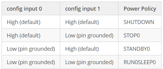
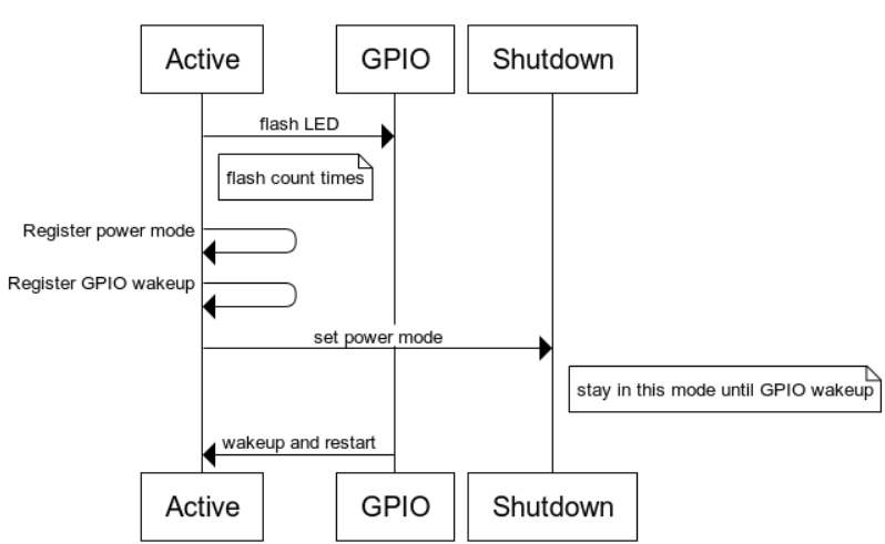
image source: the TI example referred to at the start of this blog
If you select SHUTDOWN mode, the MSPM0 wakes up when receiving a high signal on a GPIO pin. It 'll flash a led several times. Once for each time you've woken it up. Then back to SHUTDOWN.
The "flash a number of times" is interesting. This part of the example shows that we can preserve some active state (the variable counter) in SHUTDOWN mode
- Checks if it's woken up from SHUTDOWN
- If yes, increases counter, and flashes the green LED counter times.
- if not (usually, a power on or reset), it briefly flashes the blue LED.
- derives the desired low power level from the configuration pins
- sets the power policy
- saves state
- applies the set power policy
- low power
- if SHUTDOWN, wake up when GPIO pin driven high, then back to1.
Hardware resources
| switch | PA17 | J3.2 (labeled UART TX). Connect a switch or a patch wire that allows you to either select GND or 3V3 |
| LED1 | PA14 | Blue LED (on early rev 1, this is on PA26) |
| LED2 | PA27 | Green LED |
| CONFIG_0 | PA5 | J1.3 (labeled MOSI). Connect a switch or a patch wire that allows you to either select GND or 3V3 |
| CONFIG_1 | PA6 | J1.2 (labeled SCK). Connect a switch or a patch wire that allows you to either select GND or 3V3 |
Testing
The low power modes are impossible hard to test with the debugger attached. Use a multimeter, oscilloscope or power meter to assess power use in low power and active mode.
- First set the two config pins to the combination High High (SHUTDOWN).
- Verify the current
- apply 3V3 to the switch pin. Each time you do that, the device will wake up and flash the green LED, for the amount of times you woke it up.
Code highlights
In SysConfig, the switch setup is interesting:
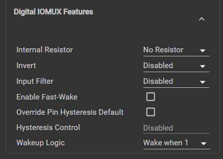
In the code, a few topics stand out:
Startup: check if we (re)start because GPIO wakeup:
    rstCause = DL_SYSCTL_getResetCause();

    if (DL_SYSCTL_RESET_CAUSE_BOR_WAKE_FROM_SHUTDOWN == rstCause)
    /* Device was woken up from a SHUTDOWN state from this GPIO pin */
    {
        /* Release IO after Shutdown before initializing any peripherals */
        SYSCFG_DL_GPIO_init();
        DL_SYSCTL_releaseShutdownIO();
        DL_GPIO_disableWakeUp(GPIO_SWITCH_USER_SWITCH_1_IOMUX);

        /* Load save state after wake from SHUTDNSTORE */
        counter = 1 + DL_SYSCTL_getShutdownStorageByte(
                          DL_SYSCTL_SHUTDOWN_STORAGE_BYTE_0);

        /* Blink LED a number of times equal to counter */
        for (blink = 0; blink < (2 * counter); blink++) {
            DL_GPIO_togglePins(GPIO_LEDS_PORT, GPIO_LEDS_USER_LED_2_PIN);
            delay_cycles(16000000);
        }
    }
Retrieve desired power policy, based on the state of the 2 config pins:
    /**
     * Resolve which Power policy to enable based on GPIO_INPUT_CONFIG_0_PIN and
     * GPIO_INPUT_CONFIG_1_PIN state.
     */
    switch (DL_GPIO_readPins(GPIO_INPUT_PORT,
        (GPIO_INPUT_CONFIG_0_PIN | GPIO_INPUT_CONFIG_1_PIN))) {
        /**
         * GPIO_INPUT_CONFIG_0_PIN and GPIO_INPUT_CONFIG_1_PIN are not connected
         * (since inputs are internally pulled high the pins will be at Vcc).
         */
        case (GPIO_INPUT_CONFIG_0_PIN | GPIO_INPUT_CONFIG_1_PIN):
            /**
             * Configure Shutdown wake-up pin to wake-up when pin is set
             * to high before changing power policy to SHUTDOWN
             */
            DL_GPIO_initDigitalInputFeatures(GPIO_SWITCH_USER_SWITCH_1_IOMUX,
                DL_GPIO_INVERSION_DISABLE, DL_GPIO_RESISTOR_NONE,
                DL_GPIO_HYSTERESIS_DISABLE, DL_GPIO_WAKEUP_ON_1);
            DL_SYSCTL_setPowerPolicySHUTDOWN();
            break;
        /**
         *  GPIO_INPUT_CONFIG_0_PIN  is not connected and
         *  GPIO_INPUT_CONFIG_1_PIN is connected to ground.
         */
        case (GPIO_INPUT_CONFIG_0_PIN):
            DL_SYSCTL_setPowerPolicySTOP0();
            break;
        /**
         *  GPIO_INPUT_CONFIG_0_PIN is connected to ground and
         *  GPIO_INPUT_CONFIG_1_PIN is not connected.
         */
        case (GPIO_INPUT_CONFIG_1_PIN):
            DL_SYSCTL_setPowerPolicySTANDBY0();
            break;
        /**
         * GPIO_INPUT_CONFIG_0_PIN and GPIO_INPUT_CONFIG_1_PIN are connected to
         * ground
         */
        default:
            DL_SYSCTL_setPowerPolicyRUN0SLEEP0();
            break;
    }
Check the shutdown clause. That's where the GPIO wakeup is configured.
Save state so that it survives the low power mode, and activate to desired power mode:
    /* Save application state before shutdown using SHUTDNSTORE */
    DL_SYSCTL_setShutdownStorageByte(
        DL_SYSCTL_SHUTDOWN_STORAGE_BYTE_0, counter);

    while (1) {
        __WFI(); /* Enter selected power policy */
    }
When you're finished
|
Low power designs can put your controller in a state, that makes it hard to reprogram it later. For this design, after you are done,
This will save you headaches later. |
Have fun!
ccs project adapted to EasyL1105: sysctl_shutdown_20250922.zip
-

DAB
-
Cancel
-
Vote Up
0
Vote Down
-
-
Sign in to reply
-
More
-
Cancel
Comment-

DAB
-
Cancel
-
Vote Up
0
Vote Down
-
-
Sign in to reply
-
More
-
Cancel
Children