


Stepper Motors are controlled by a driver IC. This blog shows how to use a Texas Instruments DRV8711 stepper motor IC with the MSPM0 controller family.
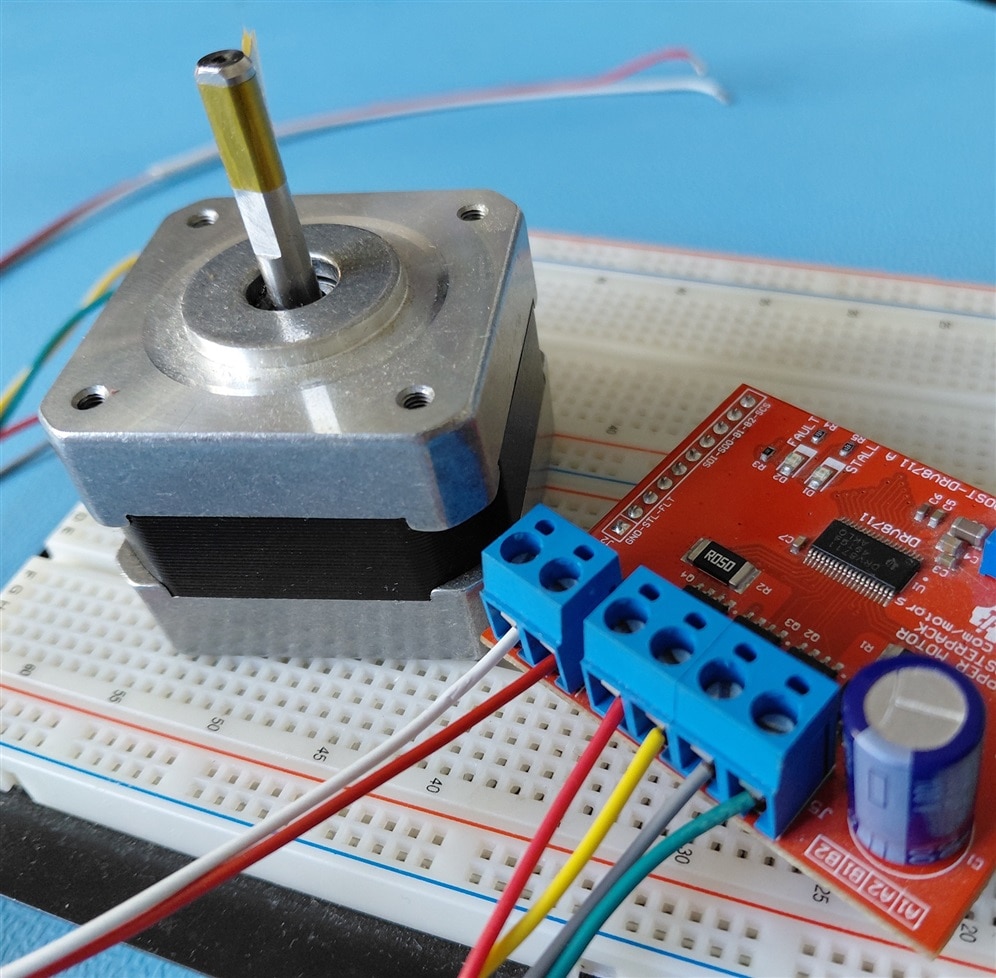
It's a port of a Raspberry Pico driver I designed for that IC:Raspberry Pico stepper driver IC library, with example: Texas Instruments DRV8711 .
This post is part of a MSPM0 stepper motor series. I've made a design for an Allegro A4899 IC earlier: MSPM0 project with VS Code, CMake and GCC - part 7b: middleware stepper motor control with A4988 stepper driver .
hardware provisioning
I use the same timers as the design with the A4988 stepper driver, and the same DIR and n_enable GPIOs.
The DRV8711 is controlled over SPI, so I'll need to enable the SPI peripheral.
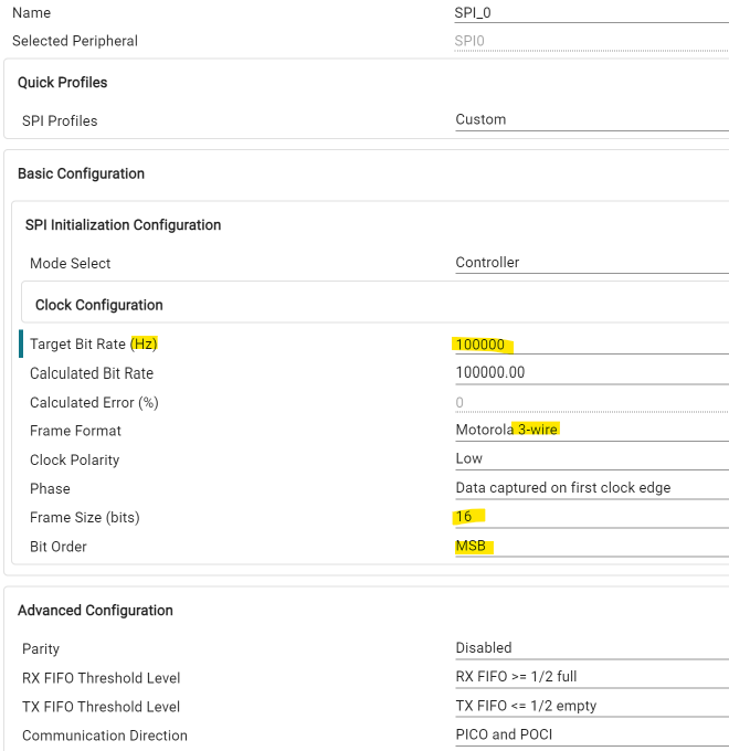
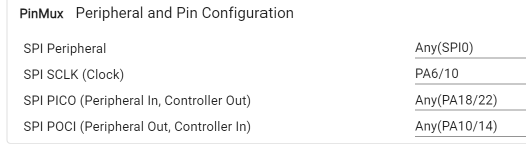
The DRV8711 requires that the CS is asserted over multiple data exchanges, so I have to implement a manual CS. That's why I selected 3-wire SPI.
Also, the CS works active high. It's different than most SPI ICs.
Here's the CS definition:
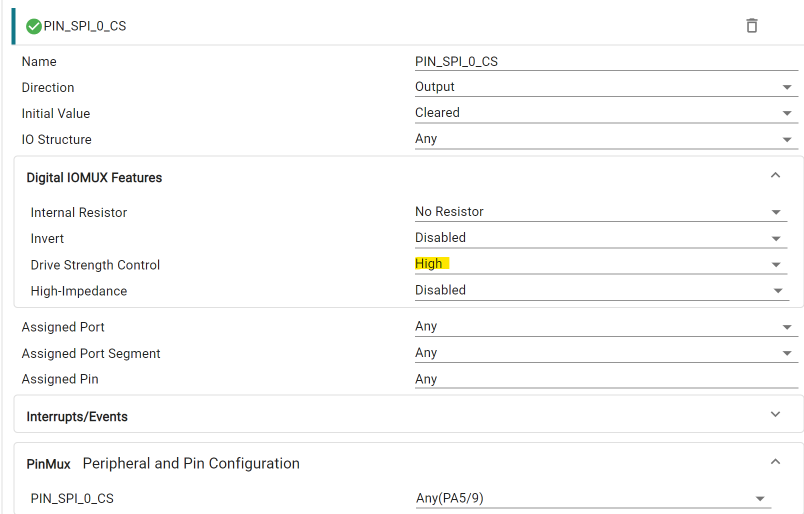
I had to select a high drive strength pin, because normal drive didn't get the job done.
other GPIOs used: reset: PA1. Just a normal Output pin.
MSPM0 DRV8711 class
I used the exact same design as the class I made for Raspberry Pico. I only ported the GPIO and SPI functions, to use the MSPM0 SDK.
/**
 * mspm0 port of DRV8711 library https://github.com/jancumps/drv8711_lib
*/

module;

/* Including all the sysconfig generated defines */
#include "ti_msp_dl_config.h"

import drv8711;
import drv8711_config;

export module drv8711_mspm0;
export namespace drv8711_mspm0 {

class drv8711_mspm0 : public drv8711::drv8711_driver {
public:
    drv8711_mspm0(SPI_Regs * spi, uint32_t cs,
        GPIO_Regs* gpio, uint32_t n_sleep, uint32_t reset) : drv8711::drv8711_driver(),
        spi_(spi), cs_(cs), gpio_(gpio), n_sleep_(n_sleep), reset_(reset) {}

    virtual void enable(bool enable) override {
        put(n_sleep_, enable);
    }

private:
    // initialise all registers from the defaults
    // defined in module drv8711_config
    // developer can override values before calling
    virtual void init_registers() {
        write(drv8711::reg_ctrl);
        write(drv8711::reg_torque);
        write(drv8711::reg_off);
        write(drv8711::reg_blank);
        write(drv8711::reg_decay);
        write(drv8711::reg_stall);
        write(drv8711::reg_drive);
        write(drv8711::reg_status);
    }

    virtual void init_spi() override{
        // Enable SPI at 1 MHz
        // cs is initiated in its own method
    }

    // users may want to use different CS with same SPI for several ICs
    // and can do that by overriding this method
    virtual void init_cs() override {
        put(cs_, false);
    }

    virtual void init_gpio() override{
        // nsleep as output
        put(n_sleep_, false);
        // reset as output
        put(reset_, false);
    }

    // write to a register
    virtual void write(uint16_t reg) override {
        SPI_Write16_Blocking(reg);
    }

    // read from a register
    virtual uint16_t read(uint16_t reg) override {
        uint16_t r_buffer;
        uint16_t w_buffer;
        w_buffer = reg | 0b1000;
        w_buffer = w_buffer << 12;
        r_buffer = SPI_WriteRead16_Blocking(w_buffer);
        return r_buffer & 0b0000111111111111; // first 4 read bits are undefined
    }

protected:
    SPI_Regs *spi_;
    uint32_t cs_; // chip select pin needs to be managed manually for this driver, as it needs to stay high accross the entire SPI transaction, which is not supported by the MSPM0 SPI driver
    GPIO_Regs* gpio_;
    uint32_t  n_sleep_;
    uint32_t  reset_;

private:
    void put(uint32_t pin, bool set) {
        DL_GPIO_writePinsVal(gpio_, pin, set ? pin : 0U);
    }

    void SPI_Write16_Blocking(uint16_t data) {
        // 1. Wait until there is space available in the SPI TX FIFO
        while (DL_SPI_isTXFIFOFull(spi_));

        // 2. Load the 16-bit data packet into the transmission register
        put(cs_, true);
        // Pad the setup time (Delays 31.25 ns, which satisfies 5 ns minimum requirement)
//        delay_cycles(1);
        DL_SPI_transmitData16(spi_, data);

        // 3. Block until the shift register completes transmission and the bus is idle
        while (DL_SPI_isBusy(spi_));
        // Pad the setup time (Delays 31.25 ns, which satisfies 5 ns minimum requirement)
        put(cs_, false);
    }

    uint16_t SPI_WriteRead16_Blocking(uint16_t dataToWrite) {
        uint16_t receivedData = 0;
        // 1. Flush any leftover garbage data out of the RX FIFO to ensure a clean transaction
        put(cs_, true);
        // Pad the setup time (Delays 31.25 ns, which satisfies 5 ns minimum requirement)
 //       delay_cycles(1);
        while (!DL_SPI_isRXFIFOEmpty(spi_)) {
            DL_SPI_receiveData16(spi_); // Read and discard
        }

        // 2. Wait until there is space available in the TX FIFO
        while (DL_SPI_isTXFIFOFull(spi_));

        // 3. Write the 16-bit variable into the transmission register
        DL_SPI_transmitData16(spi_, dataToWrite);

        // 4. Block until the RX FIFO receives the 16-bit response back from the slave
        while (DL_SPI_isRXFIFOEmpty(spi_));

        // 5. Extract and return the 16-bit data packet out of the RX FIFO
        receivedData = DL_SPI_receiveData16(spi_);
        // Pad the setup time (Delays 31.25 ns, which satisfies 5 ns minimum requirement)
//        delay_cycles(1);
        put(cs_, false);
        return receivedData;
    }

};

} // namespace drv8711_mspm0
The other classes are exact the same as used in the MSPM0 Allegro A4988 example.
test code
Also very similar as the A4988 code, except for the configuration. That's DRV8711 / SPI specific:
#include "ti_msp_dl_config.h"
#include "hal.h"
#include <array>
#include <algorithm> // for std::transform


import stepper_driver;                          // wakeup class
import drv8711;                                 // driver classes and registers
import drv8711_config;                          // register pre-configuration
import drv8711_mspm0;                           // hw driver classes and registers
import mspm0_pwm_stepper_driver;                // pwm step and dir driver
import mspm0_pwm_stepper_ramp_driver;           // pwm step and dir driver

const uint32_t dir = GPIO_GRP_DRIVER_PIN_DIR_PIN;
const uint32_t n_enable = GPIO_GRP_DRIVER_PIN_N_ENABLE_PIN;
const uint32_t cs = GPIO_GRP_DRIVER_PIN_SPI_0_CS_PIN;

const uint32_t microstep_x = 16;
const uint32_t max_step_freq = 300000;

// object to manage the drv8711 IC used for motor1
using driver_t = drv8711_mspm0::drv8711_mspm0;
driver_t driver1(SPI_0_INST, cs, GPIO_GRP_DRIVER_PORT, n_enable, microstep_x);

// object to manage the stepper motor using PWM for step and dir.
// uncomment the one to use:
// using pwm_stepper_driver_t = mspm0_pwm_stepper_driver::mspm0_pwm_stepper_driver;
using pwm_stepper_driver_t = mspm0_pwm_stepper_driver::mspm0_pwm_stepper_ramp_driver;
pwm_stepper_driver_t pwm_stepper_driver1(dir, GPIO_GRP_DRIVER_PORT, max_step_freq);


// S-curve pre-calculated profile (Speed values in Pulses Per Second / Hz)
// used by he mspm0_pwm_stepper_ramp_driver to implement a smooth acceleration and deceleration profile
const unsigned int RAMP_STEPS = 43;
// S-curve pre-calculated profile (Speed values in Pulses Per Second / Hz)
// TODO: translate to raw Hardware Timer Ticks (Highly Recommended for Performance)
inline static /*const*/ std::array<uint32_t, RAMP_STEPS> s_curve_lut = {
    150,  151,  152,  155,  160,  166,  174,  184,  196,  211,
    228,  247,  269,  293,  321,  352,  386,  424,  465,  509,
    557,  608,  662,  719,  779,  842,  908,  976,  1046, 1118,
    1191, 1265, 1340, 1414, 1489, 1563, 1636, 1707, 1777, 1845,
    1910, 1971, 2000
};

// Function to introduce a delay of approximately 200 nanoseconds
// A4988 needs this time, after changing dir/enable/microstep pins, before the next step pulse is sent
inline void wait_200ns() {
    delay_cycles(7);
}

int main() {
    SYSCFG_DL_init();

    /* Initialize the HAL module */
    HAL_init(); // TODO step away from HAL?

    // drv8711::reg_torque.torque = 0x00ff;
    driver1.init();
    driver1.microsteps(microstep_x);

    pwm_stepper_driver1.init();
    pwm_stepper_driver1.stop_motor();
    pwm_stepper_driver1.set_control_mode(mspm0_pwm_stepper_driver::control_mode::step);

    // not used by the ramp driver, but needed for the mspm0_pwm_stepper_driver::mspm0_pwm_stepper_driver to work
    // pwm_stepper_driver1.set_speed(1); // CURVE determines speed for ramp style motion, so set_speed() is not used in this example

    std::transform(s_curve_lut.begin(), s_curve_lut.end(), s_curve_lut.begin(), [](uint32_t val) {
        return val * 11.5; // Adjust the divisor to scale the speed values as needed
    });

    pwm_stepper_driver1.set_ramp(s_curve_lut); // the vector has to stay alive for the duration of the motor run, so it is stored in a static variable in this example

    /* Set the priority for interrupts */
    NVIC_SetPriority(GENERIC_PWM_CHANNEL_0_INST_INT_IRQN, 1);
    NVIC_SetPriority(TIMER_RAMP_INST_INT_IRQN, 2);

    while (1) {
        stepper_driver::wakeup w(driver1);


        pwm_stepper_driver1.set_dir(true);
        wait_200ns();
        pwm_stepper_driver1.set_step(100000);
        pwm_stepper_driver1.start_motor();

        while (pwm_stepper_driver1.is_motor_running()) {
            __WFI(); // Enter low-power sleep mode; wake on timer interrupts
        }

        pwm_stepper_driver1.set_dir(false);
        wait_200ns();
        pwm_stepper_driver1.set_step(100000);
        pwm_stepper_driver1.start_motor();

        while (pwm_stepper_driver1.is_motor_running()) {
            __WFI(); // Enter low-power sleep mode; wake on timer interrupts
        }

    }
}

extern "C" {

    void GENERIC_PWM_CHANNEL_0_INST_IRQHandler() {
        if (DL_Timer_getPendingInterrupt(GENERIC_PWM_CHANNEL_0_INST) == DL_TIMER_IIDX_ZERO) {
            pwm_stepper_driver1.check_step();
        }
    }

    void TIMER_RAMP_INST_IRQHandler(void) {
        if (DL_Timer_getPendingInterrupt(TIMER_RAMP_INST) == DL_TIMER_IIDX_ZERO) {
            pwm_stepper_driver1.check_ramp();
        }
    }

}
Before trying the design with a motor, I checked if the SPI conversations work, with a logic analyser:
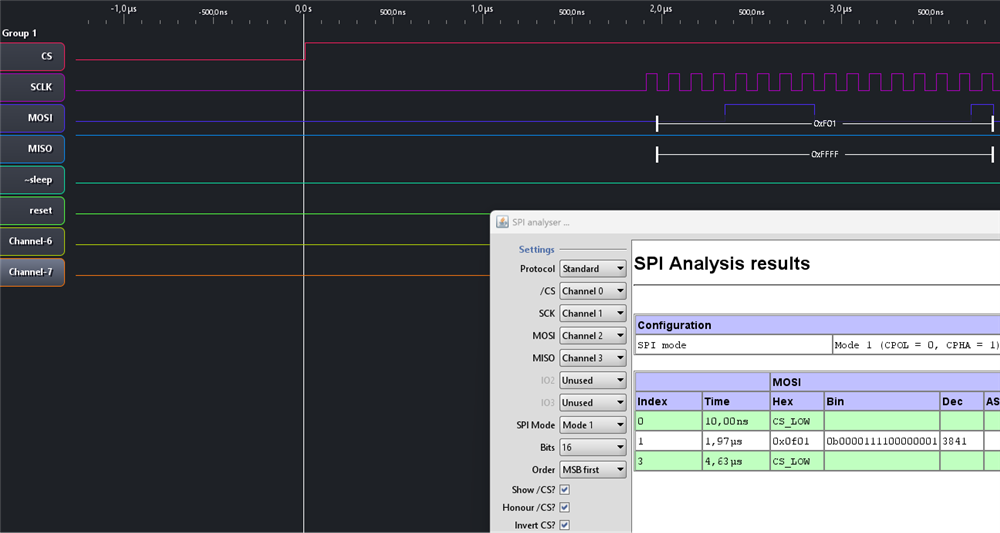
All good. And when I tried to spin a stepper motor, it worked right away. Spot the smooth operation, driven with s-curve accelerator and decelerator patterns.
Thank you for reading.
VS Code project: mspm0_stepper_ramp_drv8711_20261015_2.zip
(check this post for the expected VS Code workspace settings: MSPM0 project with VS Code, CMake and GCC - part 6: empty "template" project )
previous post: MSPM0 project with VS Code, CMake and GCC - part 7c: stepper motor control with S-shaped ramps
part of the EasyL1105 series. all posts