element14 Community
element14 Community
    Register Log In
  • Site
  • Search
  • Log In Register
  • About Us
  • Community Hub
    Community Hub
    • What's New on element14
    • Feedback and Support
    • Benefits of Membership
    • Personal Blogs
    • Members Area
    • Achievement Levels
  • Learn
    Learn
    • Ask an Expert
    • eBooks
    • element14 presents
    • Learning Center
    • Tech Spotlight
    • STEM Academy
    • Webinars, Training and Events
    • Learning Groups
  • Technologies
    Technologies
    • 3D Printing
    • FPGA
    • Industrial Automation
    • Internet of Things
    • Power & Energy
    • Sensors
    • Technology Groups
  • Challenges & Projects
    Challenges & Projects
    • Design Challenges
    • element14 presents Projects
    • Project14
    • Arduino Projects
    • Raspberry Pi Projects
    • Project Groups
  • Products
    Products
    • Arduino
    • Avnet Boards Community
    • Dev Tools
    • Manufacturers
    • Multicomp Pro
    • Product Groups
    • Raspberry Pi
    • RoadTests & Reviews
  • Store
    Store
    • Visit Your Store
    • Choose another store...
      • Europe
      •  Austria (German)
      •  Belgium (Dutch, French)
      •  Bulgaria (Bulgarian)
      •  Czech Republic (Czech)
      •  Denmark (Danish)
      •  Estonia (Estonian)
      •  Finland (Finnish)
      •  France (French)
      •  Germany (German)
      •  Hungary (Hungarian)
      •  Ireland
      •  Israel
      •  Italy (Italian)
      •  Latvia (Latvian)
      •  
      •  Lithuania (Lithuanian)
      •  Netherlands (Dutch)
      •  Norway (Norwegian)
      •  Poland (Polish)
      •  Portugal (Portuguese)
      •  Romania (Romanian)
      •  Russia (Russian)
      •  Slovakia (Slovak)
      •  Slovenia (Slovenian)
      •  Spain (Spanish)
      •  Sweden (Swedish)
      •  Switzerland(German, French)
      •  Turkey (Turkish)
      •  United Kingdom
      • Asia Pacific
      •  Australia
      •  China
      •  Hong Kong
      •  India
      •  Korea (Korean)
      •  Malaysia
      •  New Zealand
      •  Philippines
      •  Singapore
      •  Taiwan
      •  Thailand (Thai)
      • Americas
      •  Brazil (Portuguese)
      •  Canada
      •  Mexico (Spanish)
      •  United States
      Can't find the country/region you're looking for? Visit our export site or find a local distributor.
  • Translate
  • Profile
  • Settings
Experts, Learning and Guidance
  • Technologies
  • More
Experts, Learning and Guidance
Ask an Expert Forum Colorsound Power Boost - Another issue!!!
  • Blog
  • Forum
  • Documents
  • Leaderboard
  • Files
  • Members
  • Mentions
  • Sub-Groups
  • Tags
  • More
  • Cancel
  • New
Join Experts, Learning and Guidance to participate - click to join for free!
Actions
  • Share
  • More
  • Cancel
Forum Thread Details
  • Replies 40 replies
  • Subscribers 289 subscribers
  • Views 5383 views
  • Users 0 members are here
Related
See a helpful answer?

Be sure to click 'more' and select 'suggest as answer'!

If you're the thread creator, be sure to click 'more' then 'Verify as Answer'!

Colorsound Power Boost - Another issue!!!

Andy Betts
Andy Betts over 4 years ago

Hi guys,


Been a long time since I posted here and i have another issue for you that hopefully you might be able to help with.


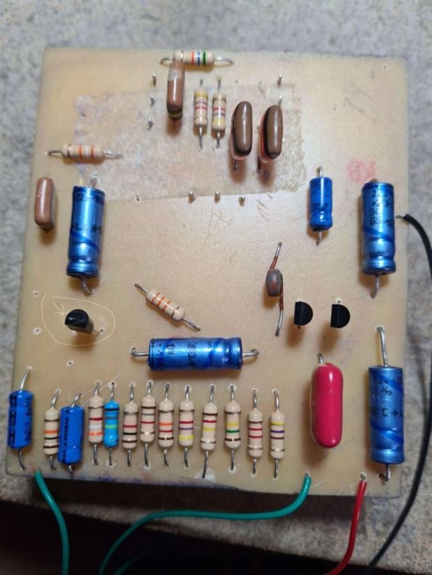
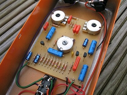
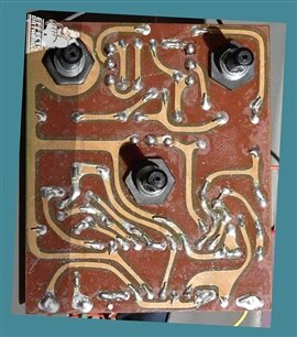
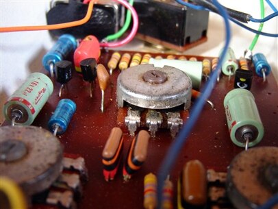
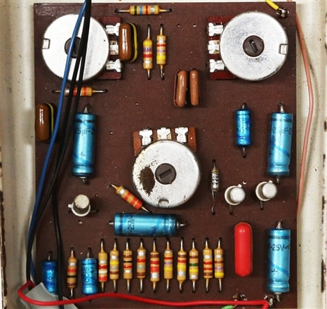
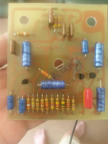
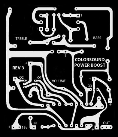
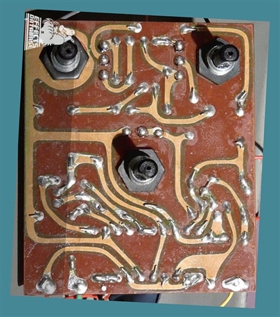
I've just recently built another Power boost pedal for a client. I etched the board myself using the photo resist method, it came out not too bad save for a couple of areas where the tracks were broke. i patched them up with copper tape that has conductive adhesive. I've checked for continuity and all is fine where the patches are. Here are the pictures of the board and also for reference the schematic.


image


image


I've built a few of these now and have had no issues with the circuit or builds until now. I built this one, wired it to my test rig and there is no sound at all.... it's totally dead as if it's not in the circuit at all. I've checked for voltage on input and it's ok. I've checked for continuity in the circuit and it seems ok. i don't know what the voltages should be in the various sections of the circuit so haven't checked them. I've gone basic and checked the input and output wires for breaks and they're ok. I've also checked the test rig with a known good circuit and it's OK.


i think there might be a duff component but not sure on first steps to troubleshoot.... Any help will be greatly received.

  • Sign in to reply
  • Cancel

Top Replies

  • michaelkellett
    michaelkellett over 4 years ago in reply to Andy Betts +3
    What value is the blue bodied resistor - it looks like 1.8M brown grey green - if its meant to be 180k that would explain things. I could be being misled by pictures. MK
  • Jan Cumps
    Jan Cumps over 4 years ago in reply to geralds +3
    geralds wrote: ... Tip: use your finger as a signal injector. - You are a 60Hz (in AUT I'm a 50Hz sender ) sender "brummmmmm.....!!!""", so you can check the signal with a signal follower (mini-amp with…
  • Andy Betts
    Andy Betts over 4 years ago +3
    I've taken a higher res photo of the board.... this is how it stand now after reflowing the 3k9 resistor and bridging the break in the track on the Q3 base
  • geralds
    geralds over 4 years ago in reply to Andy Betts

    image

    The Q3, is this transistor broken? It seems that there is a burned hole.

    What's the name of the 3 transistors?

    The PCB, hm.... are the pots on an fixed place, or can you rearrange all parts on the board?

    Because it is better, if you makes a smaller board with optimized track wiring.

    Also the parts, for such tone control preamp they are a bit big.

    How look the other boards, which are working right? Are they with the same layout?


    Tip:

    You can check the basic functionality of the transistor with an Ohm-Meter.

    For an NPN: plus (red pin of the meter)  to B and minus to C or E, and the Ohm are low; or minus to B and plus to C or E, and the Ohm are high (MOhm or more).

    For an PNP: minus to B and plus to C or E, the Ohms are low.

    If you check E to C, a good transistor has an "endless" Ohm (GOhm), otherwise the diodes in the tr. were melted.

    Or you can also check the tr. with an diode-meter, or you have a transistortesting on your multimeter.

    Gerald

    ---

    • Cancel
    • Vote Up +1 Vote Down
    • Sign in to reply
    • Cancel
  • dougw
    dougw over 4 years ago in reply to Andy Betts

    If that resistor has 15 volts on one side and 0 volts on the other side, then I think you are looking for a short from Q3 collector to ground, not an open circuit.

    A fried transistor or a mix-up of EBC cannot short the collector resistor to ground in this circuit.

    • Cancel
    • Vote Up 0 Vote Down
    • Sign in to reply
    • Cancel
  • Jan Cumps
    Jan Cumps over 4 years ago

    In a next version, I'd drill mounting holes in the board.

    If it hangs in the pedal, held up by the potentioleter pins, I predict that you'll get broken solder joints.

    A pedal gets some abuse when used on stage. And your PCB, with the electrolytes, has a decent mass.

    • Cancel
    • Vote Up 0 Vote Down
    • Sign in to reply
    • Cancel
  • Andy Betts
    Andy Betts over 4 years ago in reply to Jan Cumps

    @Jan Crumps Only the pots are board mounted, the on/off switch is separate.

    @Gerald Schwarz The board is an exact replica of an original. All the parts are as an original 0.5w resistors, and Vishay axial capacitors. Here are some photos of some original powerboosts. All the other boards I've made have been perfect, with no issues. This has clearly got to be a component issue.


    imageimageimage


    The transistors are BC183L the same as an original and are orientated correctly, although I will check to be sure. Pinout is ECB when looking at the transistors from the pin end with the flat on top. The only difference with mine is I've had to mount the pots on the reverse side of  the board as the pot shaft isn't long enough to locate on the board and go through the enclosure. The originals used the pot shaft to mount to the board, where mine use the 3 pins. Also, the originals had the pins bent in the opposite direction to standard angled pot. The originals used custom made pots by Omeg and are not readily available.

    • Cancel
    • Vote Up 0 Vote Down
    • Sign in to reply
    • Cancel
  • Andy Betts
    Andy Betts over 4 years ago in reply to dougw

    I'll have a look

    • Cancel
    • Vote Up 0 Vote Down
    • Sign in to reply
    • Cancel
  • Andy Betts
    Andy Betts over 4 years ago in reply to Andy Betts

    Sorry, the transistors are BC184L... that was a typo

    • Cancel
    • Vote Up 0 Vote Down
    • Sign in to reply
    • Cancel
  • geralds
    geralds over 4 years ago in reply to Andy Betts

    Andy Betts  wrote:


    @Jan Crumps Only the pots are board mounted, the on/off switch is separate.

    @Gerald Schwarz The board is an exact replica of an original. All the parts are as an original 0.5w resistors, and Vishay axial capacitors. Here are some photos of some original powerboosts. All the other boards I've made have been perfect, with no issues. This has clearly got to be a component issue.


    imageimageimage


    The transistors are BC183L the same as an original and are orientated correctly, although I will check to be sure. Pinout is ECB when looking at the transistors from the pin end with the flat on top. The only difference with mine is I've had to mount the pots on the reverse side of  the board as the pot shaft isn't long enough to locate on the board and go through the enclosure. The originals used the pot shaft to mount to the board, where mine use the 3 pins. Also, the originals had the pins bent in the opposite direction to standard angled pot. The originals used custom made pots by Omeg and are not readily available.

    ---

    Thank you for the images.

    image

    Please check the polcap on the right side, at the red wire (compare with the original board).

    This polcap is wrong rotated. The minus polarity must be on the output-pin (see in the schematics).

    The Q3 transistor looks damaged. Is there a hole on top of this transistor?

    The 220p cap at the Q2 transistor, is this a ceramic cap with this value? It looks not as such cer_cap.

    The treble pot seems not tined right.


    Tip:

    renumber all parts in the schematics, e.g. R1, R2, R3.... C1, C2, C3,.... T1, T2, T3,..... and so on.

    So you can find it easy on the board.


    Tip:

    This amp is a module. It has an input and an output terminated to GND. So all polcaps must be polarized right to plus (the internal pin is plus, the case is minus)

    At the end of the board all outside connected modules also are terminated to GND.

    So, then you have two polcaps connected in serial minus-minus as a "bipolar polcap".


    image

    Please see the functions of a polcap and bipolar polcap in audio applications, as well the functions of caps types MKT, MKP, MKS, styroflex, ceramic.


    Best Regards

    Gerald

    • Cancel
    • Vote Up 0 Vote Down
    • Sign in to reply
    • Cancel
  • Jan Cumps
    Jan Cumps over 4 years ago in reply to Andy Betts

    Andy Betts  wrote:


    @Jan Crumps Only the pots are board mounted, the on/off switch is separate.

    ...


    imageimageimage


    .... The only difference with mine is I've had to mount the pots on the reverse side of  the board as the pot shaft isn't long enough to locate on the board and go through the enclosure. The originals used the pot shaft to mount to the board, where mine use the 3 pins. ...

    That's what I try to indicate. The originals used the housing and nut for rigidity. They are made for that.

    You are using the 3 solder pins. It will not hold. Guaranteed.

    Either the pins will break out of the solder, the solder will break off the pads or the pads will get ripped of the PCB. But it will not mechanically hold.

    • Cancel
    • Vote Up +1 Vote Down
    • Sign in to reply
    • Cancel
  • Andy Betts
    Andy Betts over 4 years ago in reply to geralds

    The polecap is orientated correctly, the polecap is on the V in not the output..... Here is a photo of a board from 1969 which my pedal is based on... It's pretty much Identical. The output polecap is the little on e on the far left of the board.


    image


    Below are 2 photos from 2 previous builds I did which worked perfectly.... No change in any component placement.


    imageimage


    here is my board design on the left, and the original on the right for comparison. You can see I've marked the "+" signs on my board to prevent incorrect orientation


      imageimage

    • Cancel
    • Vote Up 0 Vote Down
    • Sign in to reply
    • Cancel
  • geralds
    geralds over 4 years ago in reply to Andy Betts

    Yes, thank you.

    It was my mistake, I didn't mirror my view (top // bot mirroring) in this area.

    • Cancel
    • Vote Up 0 Vote Down
    • Sign in to reply
    • Cancel
<>
element14 Community

element14 is the first online community specifically for engineers. Connect with your peers and get expert answers to your questions.

  • Members
  • Learn
  • Technologies
  • Challenges & Projects
  • Products
  • Store
  • About Us
  • Feedback & Support
  • FAQs
  • Terms of Use
  • Privacy Policy
  • Legal and Copyright Notices
  • Sitemap
  • Cookies

An Avnet Company © 2025 Premier Farnell Limited. All Rights Reserved.

Premier Farnell Ltd, registered in England and Wales (no 00876412), registered office: Farnell House, Forge Lane, Leeds LS12 2NE.

ICP 备案号 10220084.

Follow element14

  • X
  • Facebook
  • linkedin
  • YouTube