element14 Community
element14 Community
    Register Log In
  • Site
  • Search
  • Log In Register
  • Community Hub
    Community Hub
    • What's New on element14
    • Feedback and Support
    • Benefits of Membership
    • Personal Blogs
    • Members Area
    • Achievement Levels
  • Learn
    Learn
    • Ask an Expert
    • eBooks
    • element14 presents
    • Learning Center
    • Tech Spotlight
    • STEM Academy
    • Webinars, Training and Events
    • Learning Groups
  • Technologies
    Technologies
    • 3D Printing
    • FPGA
    • Industrial Automation
    • Internet of Things
    • Power & Energy
    • Sensors
    • Technology Groups
  • Challenges & Projects
    Challenges & Projects
    • Design Challenges
    • element14 presents Projects
    • Project14
    • Arduino Projects
    • Raspberry Pi Projects
    • Project Groups
  • Products
    Products
    • Arduino
    • Avnet Boards Community
    • Dev Tools
    • Manufacturers
    • Multicomp Pro
    • Product Groups
    • Raspberry Pi
    • RoadTests & Reviews
  • Store
    Store
    • Visit Your Store
    • Choose another store...
      • Europe
      •  Austria (German)
      •  Belgium (Dutch, French)
      •  Bulgaria (Bulgarian)
      •  Czech Republic (Czech)
      •  Denmark (Danish)
      •  Estonia (Estonian)
      •  Finland (Finnish)
      •  France (French)
      •  Germany (German)
      •  Hungary (Hungarian)
      •  Ireland
      •  Israel
      •  Italy (Italian)
      •  Latvia (Latvian)
      •  
      •  Lithuania (Lithuanian)
      •  Netherlands (Dutch)
      •  Norway (Norwegian)
      •  Poland (Polish)
      •  Portugal (Portuguese)
      •  Romania (Romanian)
      •  Russia (Russian)
      •  Slovakia (Slovak)
      •  Slovenia (Slovenian)
      •  Spain (Spanish)
      •  Sweden (Swedish)
      •  Switzerland(German, French)
      •  Turkey (Turkish)
      •  United Kingdom
      • Asia Pacific
      •  Australia
      •  China
      •  Hong Kong
      •  India
      •  Korea (Korean)
      •  Malaysia
      •  New Zealand
      •  Philippines
      •  Singapore
      •  Taiwan
      •  Thailand (Thai)
      • Americas
      •  Brazil (Portuguese)
      •  Canada
      •  Mexico (Spanish)
      •  United States
      Can't find the country/region you're looking for? Visit our export site or find a local distributor.
  • Translate
  • Profile
  • Settings
Experts, Learning and Guidance
  • Technologies
  • More
Experts, Learning and Guidance
Ask an Expert Forum Help with Making a RPM tacho Shift Light circuit open a 12v Relay
  • Blog
  • Forum
  • Documents
  • Leaderboard
  • Files
  • Members
  • Mentions
  • Sub-Groups
  • Tags
  • More
  • Cancel
  • New
Join Experts, Learning and Guidance to participate - click to join for free!
Actions
  • Share
  • More
  • Cancel
Forum Thread Details
  • State Not Answered
  • Replies 19 replies
  • Subscribers 281 subscribers
  • Views 3699 views
  • Users 0 members are here
  • ask_an_expert
  • led
  • rpm
Related
See a helpful answer?

Be sure to click 'more' and select 'suggest as answer'!

If you're the thread creator, be sure to click 'more' then 'Verify as Answer'!

Help with Making a RPM tacho Shift Light circuit open a 12v Relay

Former Member
Former Member over 10 years ago

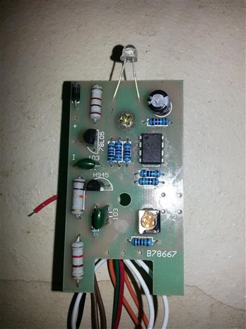
Hi everyone, i have a few adjustable Tachometer Shift light Circuits that i want to use to turn on a relay when the led turns on.

The way they are set up now:
You can adjust the desired rpm Shift light value with a pot then when that rpm is reached the led turns on.


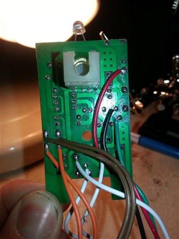
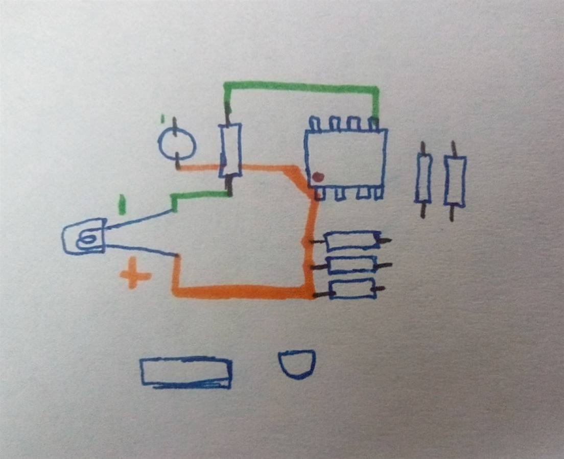
My problem is tracing it back to the IC or to the nearest transistor.
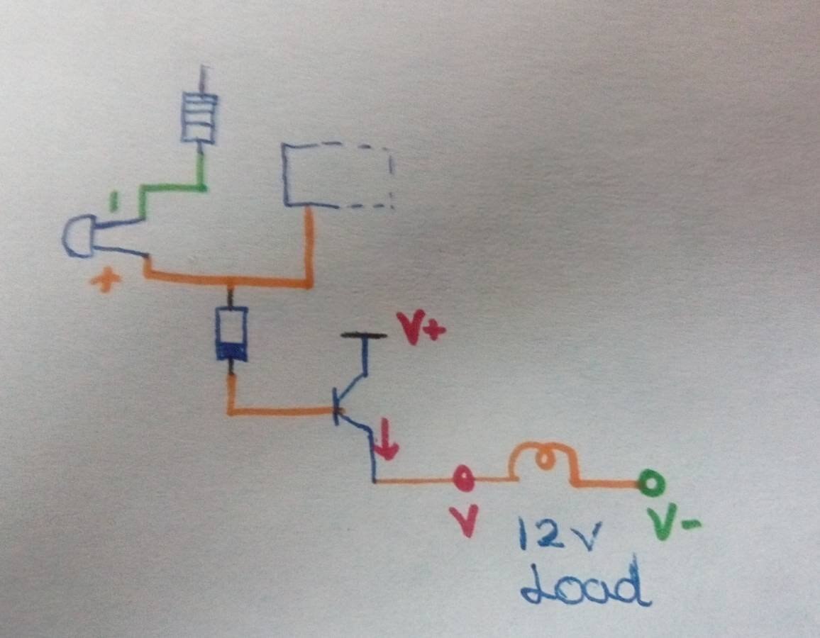
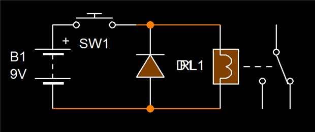
I'm trying to turn on a 12v relay when the desired rpm is reached.


So there are 2 ways i am thinking of doing this...


1: is to use a transistor to allow a higher current to run through the relay's solenoid to then allow me to run a separate 12v circuit to turn on more than 1 led light. i cant find where to run the transistor off or which pin on the ic is actually the "remote wire" for the led.


2: If i can't use a transistor is it possible to use a phototransistor and just use the built in led to then turn on a second circuit with a phototransitor linked to the relay's solenoid>


Any help would be greatly appreciated please find some pictures attached of the circuitimage


image

  • Sign in to reply
  • Cancel
  • supper_slash
    0 supper_slash over 10 years ago

    Please allow more specifics. Like.


    What are you needing out of the relay. (12V 1A)?

    SPST or DPDT?


    If so, here is an idea. Remove the led, replace it with a solid state relay, And replace the led off of the relay load side of the circuit.


    Off the top of my head here is a relay that may work. But you will need to look around and see if this will fit your needs.

    You may need a DPDT, or something handling more power, etc.


    But let me know what you think of this solution.

    • Cancel
    • Vote Up 0 Vote Down
    • Sign in to reply
    • Verify Answer
    • Cancel
  • Robert Peter Oakes
    0 Robert Peter Oakes over 10 years ago in reply to supper_slash

    It may also be possible to use a low voltage (On the input) solid state relay , this would provide isolation and an easy interface ?, optionally an opto isolator in series or replacing the LED in question with same result


    Peter

    • Cancel
    • Vote Up 0 Vote Down
    • Sign in to reply
    • Verify Answer
    • Cancel
  • Former Member
    0 Former Member over 10 years ago in reply to Robert Peter Oakes

    Thankyou for your replies,


    I have a fairly good understanding of simple electronics and some more technical things but IC's and this style circuit are still new to me.


    I didn't understand this circuit and what the led was actually doing.


    when i tested it with a multimeter and connecting between the pos or neg pins on the led i was always getting voltage even when the led was off just when the shift light was turned on i was getting more.


    I only need a spst relay on it and about 1-2 amps would be max if i needed more i could run a larger relay off that one anyway.


    i tried unsoldering the led and running a relay off the same pins but it didnt work because it wasnt turning it on or off and of course the voltage at the pins is 3.5v for the blue led so unless i can get a relay that has a 3-5v turn on then can handle 12v through?


    hope this helps a little sorry for my lack of knowledge 

    • Cancel
    • Vote Up 0 Vote Down
    • Sign in to reply
    • Verify Answer
    • Cancel
  • Robert Peter Oakes
    0 Robert Peter Oakes over 10 years ago in reply to Former Member

    the LED drivers will not have anything close to the power needed to turn on a relay, you will need to use an opto isolator or at least a transistor to do the job


    See this for a bit of a backgrounder http://www.element14.com/community/groups/internet-of-things/blog/2014/08/05/drive-big-things-with-added-safety-opto-isolators

    • Cancel
    • Vote Up 0 Vote Down
    • Sign in to reply
    • Verify Answer
    • Cancel
  • Former Member
    0 Former Member over 10 years ago in reply to Robert Peter Oakes

    I checked out your link Peter.

    I have also tried to use a transistor on the led leg without any success. I wasnt sure what i exactly needed or what would work. When testing i know it always had voltage between both pins of the leds and their opposing supplies.


    For example when i tested the voltage between the pos pin on the led and the ground i got a voltage and then the same thing happened between the neg pin on the led and the positive supply even when the led was turned off yet no voltage between the led's pins themselves.


    I think from memory the negative pin was earthed straight to the negative so must have some form of positive change when reaching the desired rpm from the frequency- voltage chip.


    so if it is a "switched positive" is there a particular type of npn transistor i need to use or is there a huge range that would work?


    Thankyou.   

    • Cancel
    • Vote Up 0 Vote Down
    • Sign in to reply
    • Verify Answer
    • Cancel
  • mudz
    0 mudz over 10 years ago

    Greetings,
    I have figured out little info about the circuit check the following images.

    image

    If I am guessing it right, looking at the led the internal right side(near capacitor) is larger which is negative part of led. So that pin is connected with resistor which is connected with 5th pin of IC. Now, the positive pin is connected with three resistor and the 1st pin of IC which I guess is the input to the led(this pins voltage is driving the led). Also if you look at the capacitor, you will find that the capacitor's positive pin is connected to the 1st pin of IC which also confirms that it is the input to the led. This part, I guess, you already knew.
    Consider this circuit :

    image

    As you have mentioned that even when LED is off it is getting some voltage, I suggest you to add a Diode which will give a voltage drop of around ~0.7v (as shown in image). If again transistor stays on try adding another diode in series, total voltage drop will be around ~1.4v. I guess it will do the job. Don't forget to add resistor in between v+ and collector of transistor. For transistor consider TIP120, TIP31 ...
    If this does not works, Please mention few things like:
    1. IC number/Name
    2. voltage across led when it is off.
    3. Few more Images(without reflection, shadow).
    4. Voltages across red & black wire, red & green wire.
    5. Mention Circuit driving voltage(as I can see 1 watt or 2 watt resistors)


    Good Luck image

    • Cancel
    • Vote Up 0 Vote Down
    • Sign in to reply
    • Verify Answer
    • Cancel
  • Robert Peter Oakes
    0 Robert Peter Oakes over 10 years ago in reply to mudz

    In the circuit you depict here I would have guessed the orange line is the positive power rail and therefore would not change much, the green line through the resistor I would have guessed to be the control line for the LED and the resistor between it and the pin on the IC is to limit the current through the LED.


    The additional transistor in this case would not work as the supply rail for the chip is unlightly to be 12V, the transistor would have to be PNP and turn on then the base is pulled low, if it is NPN then the base would have to exced 12V in order to deliver 12V to the relay, if the chip is a 5V device then you will get about 4V only to the relay (Standard emitter follow). You indicate the transistor is NPN based on the description and the direction of the included DIODE. You have no current limiting in the circuit to the base so this could be an issue


    I would suggest putting the transistor on the other side of the relay (12V to the relay, relay to the collector of the transistor and the emitter of the transistor to ground. put a few hundred ohms resistor between the base and the control signal


    I would actually suggest measuring what is happening on the chip where you indicate the resistor is connected, this would be pin 5 by convention with the assumption the dot on the chip is pin 1 (Normal convention)


    this pin I would expect to go from high volts when the LED is off, to close to ground when the LED is on, if this is the case you can use a NPN transistor to hold of a PNP transistor that in turn drives the relay (This provides a level of isolation from the 12 V to the chip which can not be avoided with only one transistor


    Hope this helps


    Peter

    • Cancel
    • Vote Up 0 Vote Down
    • Sign in to reply
    • Verify Answer
    • Cancel
  • Robert Peter Oakes
    0 Robert Peter Oakes over 10 years ago

    remind me again, what is the chip part number, if I am not clear from my waffiling above, I will draw up a diagram tonight for you

    • Cancel
    • Vote Up 0 Vote Down
    • Sign in to reply
    • Verify Answer
    • Cancel
  • mudz
    0 mudz over 10 years ago in reply to Robert Peter Oakes
    In the circuit you depict here I would have guessed the orange line is the positive power rail and therefore would not change much,

    You might be right because this is another way that this led is powered, but conventional way to power a led is by giving voltage to the positive pin while keeping negative pin at ground. Your case is true too.

    the green line through the resistor I would have guessed to be the control line for the LED and the resistor between it and the pin on the IC is to limit the current through the LED.

    This might be also true, but current limiting resistor can be connected both ways i.e on positive pin as well as on negative pin of led to limit the current.

    The additional transistor in this case would not work as the supply rail for the chip is unlightly to be 12V, the transistor would have to be PNP and turn on then the base is pulled low, if it is NPN then the base would have to exced 12V in order to deliver 12V to the relay, if the chip is a 5V device then you will get about 4V only to the relay (Standard emitter follow). You indicate the transistor is NPN based on the description and the direction of the included DIODE. You have no current limiting in the circuit to the base so this could be an issue

    I have mentioned that the transistor is supplied with v+ but i forgot to mention it should be 12v as we can drive the 12v load directly, but this is the option 1(without relay). Transistors i have mentioned are of 3A/5A rating.

    Current limiting resistor can be added to the base, The idea was to get the circuit up early and then do the minor corrections.

    I would suggest putting the transistor on the other side of the relay (12V to the relay, relay to the collector of the transistor and the emitter of the transistor to ground. put a few hundred ohms resistor between the base and the control signal

    Again another case and true but whenever there is a relay in the circuit I prefer to go with optocoupler/optoisolator. So this circuit can be used for this case too. You can use system supply at v+ and the where I have connected load that can be used to drive optocoupler which in turns drive the relay(connected with external 12v supply).

    • Cancel
    • Vote Up 0 Vote Down
    • Sign in to reply
    • Verify Answer
    • Cancel
  • supper_slash
    0 supper_slash over 10 years ago

    Here is the setup for the circuit.

    The positive, and negative orientation of the diode is the key.

    image

    • Cancel
    • Vote Up 0 Vote Down
    • Sign in to reply
    • Verify Answer
    • Cancel
>
element14 Community

element14 is the first online community specifically for engineers. Connect with your peers and get expert answers to your questions.

  • Members
  • Learn
  • Technologies
  • Challenges & Projects
  • Products
  • Store
  • About Us
  • Feedback & Support
  • FAQs
  • Terms of Use
  • Privacy Policy
  • Legal and Copyright Notices
  • Sitemap
  • Cookies

An Avnet Company © 2025 Premier Farnell Limited. All Rights Reserved.

Premier Farnell Ltd, registered in England and Wales (no 00876412), registered office: Farnell House, Forge Lane, Leeds LS12 2NE.

ICP 备案号 10220084.

Follow element14

  • X
  • Facebook
  • linkedin
  • YouTube