This week has been a very challenging one to be sure...
I ended last week with a problem with the primary external hard drive that contains the Ubuntu Virtual Machines that I use for Xilinx development tools. I was intermittently getting files missing or corrupted. Extremely frustrating, but I managed to move my project setup to a new drive. I also encountered a strange problem when I incorporated the PmodBLE into my project. It took me a while to figure out that none of the other 3 Pmods (PmodNav, PmodOLED, or PModOLEDrgb) would function when I included the PmodBLE in the hardware platform I exported from Vivado. The 3 Pmods would all work together, but none would work in any combination (even individually) with the PmodBLE. Somewhat perplexing because the PmodBLE basically just interfaces via a UART. And the PmodBLE works fine on its own and with the board GPIO (LEDs, switches and buttons). Quite maddening and I still haven't figured it out.
Of course, it doesn't help that we've had extremely hot weather recently (9 days so far in the mid to upper 90s - a couple over 100 F). I had to move my development setup downstairs to try to keep reasonably cool. Seems like the weather all over the world is going crazy again this year.
For my challenge experiment I had intended to do a WebBLE interface with the IMU (PmodNAV) on the Arty S7. With my current problems, I don't think that I have enough time left in the Challenge to get that to work. So instead, I've decided to use the integrated XADC on the Arty S7 and interface it to the Serial Bluetooth Terminal on my Android tablet.
The XADC Block contains two 12-bit, 1 MSPS ADCs. These ADCs are available for use with both external analog inputs and on-chip sensors. These sensors and external inputs are shown in the Block Diagram:
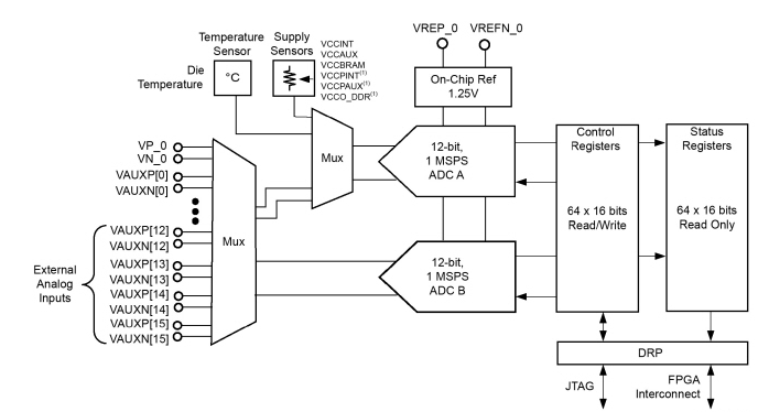
The on-chip sensors include die temperature and power rails. There are 17 external differential inputs (one dedicated pin pair and 16 dual-purpose pin pairs) that can be connected to the ADCs through an internal mux. The dual-purpose (aux) pins can also be configured as digital I/O. Each differential pair can be configured as a single-ended (unipolar or bipolar) input or a differential input. The on-chip sensors are used in the sysmon application to monitor device health and can be configured with programmable alarms. The analog inputs have a differential range of 1V (0 to 1V or +/-0.5V).
Vivado Platform
The IP element in Vivado is the XADC Wizard. Here is the Block Diagram image showing the external inputs and alarm outputs.
XADC Wizard
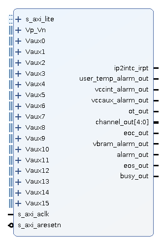
The XADC IP can be configured to continuously sequence through selected channels for measurement. I set up that mode.
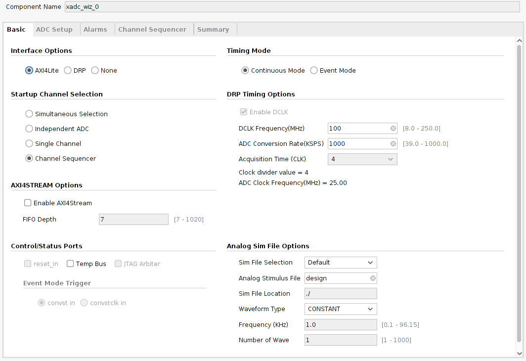
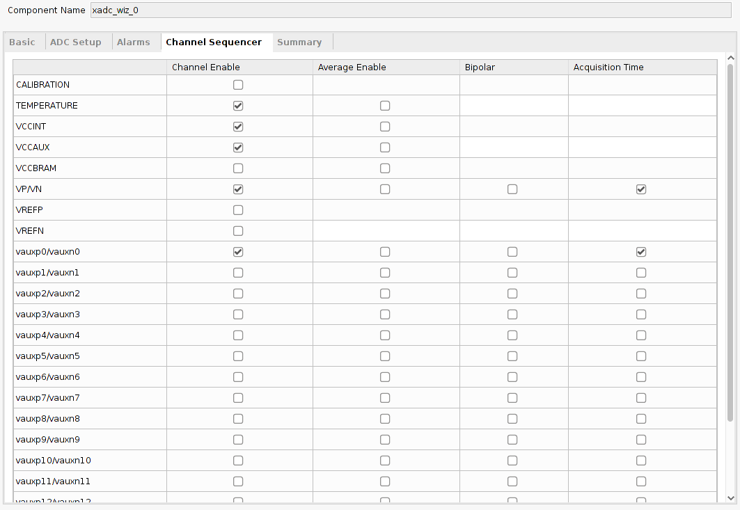
I selected the die temperature, VCC internal and VCC aux sensors and external channels Vp_Vn, Vaux0, and Vaux15.
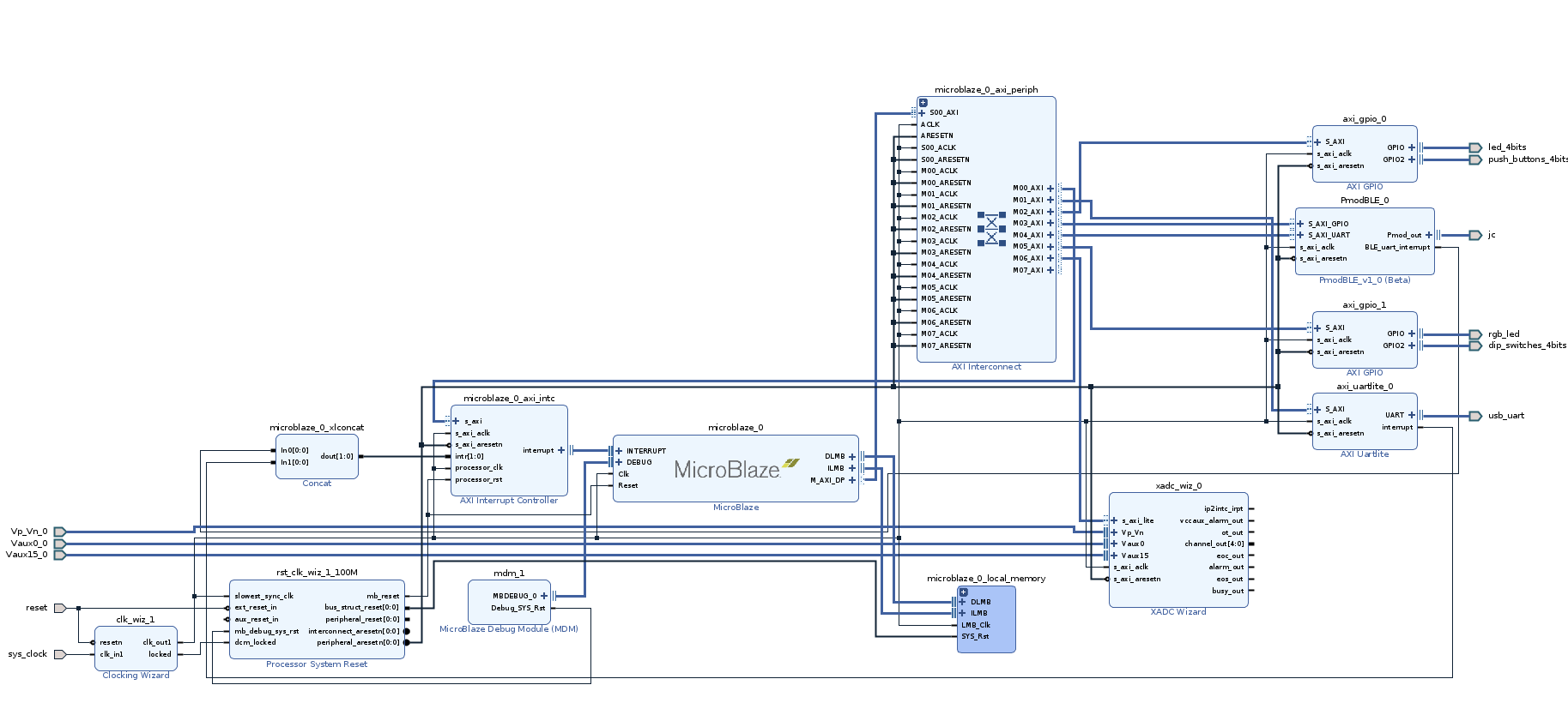
Here is the project block diagram with the external inputs:
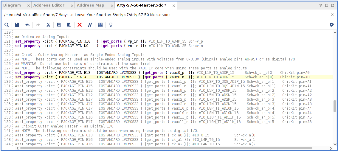
Arty-S7-50-Master.xdc constraints file must be modified to uncomment the desired external pin connections for the ADC.
Vitis Application
It turns out that there is a Vitis Application template that has a SysMonPolledExample that configures the XADC for making measurements. I am going to adapt that example to sample the appropriate internal sensors and external inputs and merge it with my BLE code. That template is called "Peripheral Tests".
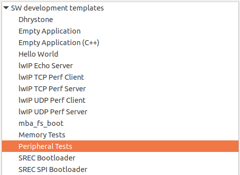
It's essentially equivalent to using a library. I copied the code files and headers. The application src directory in the Vitis Explorer window:
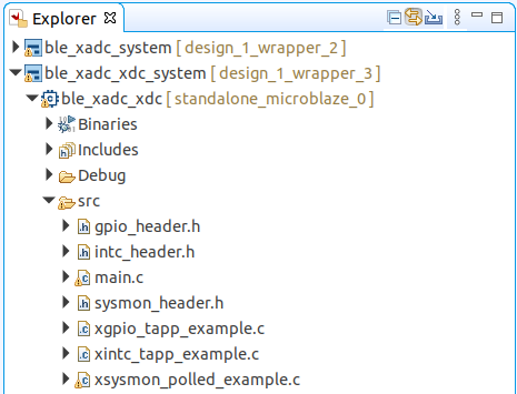
The key to using the SysMon code is determining the "name Indexes" for the ADC channels and finding the appropriate functions to use read the data. All of that information is contained in the sysmon_header.h and the modified xsysmon_polled_example.c files. I've excerpted sections below:
name Indexes
/************************** Constant Definitions ****************************/

/**
 * @name Indexes for the different channels.
 * @{
 */
#define XSM_CH_TEMP		        0x0  /**< On Chip Temperature */
#define XSM_CH_VCCINT		    0x1  /**< VCCINT */
#define XSM_CH_VCCAUX		    0x2  /**< VCCAUX */
#define XSM_CH_VPVN		        0x3  /**< VP/VN Dedicated analog inputs */
#define XSM_CH_VREFP		    0x4  /**< VREFP */
#define XSM_CH_VREFN		    0x5  /**< VREFN */
#define XSM_CH_VBRAM	    	0x6  /**< VBRAM - 7 Series and Zynq */
#define XSM_CH_SUPPLY_CALIB	    0x07 /**< Supply Calib Data Reg */
#define XSM_CH_ADC_CALIB	    0x08 /**< ADC Offset Channel Reg */
#define XSM_CH_GAINERR_CALIB 	0x09 /**< Gain Error Channel Reg  */
#define XSM_CH_AUX_MIN		    16   /**< Channel number for 1st Aux Channel */
#define XSM_CH_AUX_MAX		    31   /**< Channel number for Last Aux channel */
Read and convert XADC data
	/*
	 * Read the ADC converted Data from the data registers for on-chip
	 * temperature and on-chip VCCAUX
	 */
	TempData = XSysMon_GetAdcData(SysMonInstPtr, XSM_CH_TEMP);
	VccintData = XSysMon_GetAdcData(SysMonInstPtr, XSM_CH_VCCINT);
	VccauxData = XSysMon_GetAdcData(SysMonInstPtr, XSM_CH_VCCAUX);
	VpVnData = XSysMon_GetAdcData(SysMonInstPtr, XSM_CH_VPVN);
	Vauxp0Data = XSysMon_GetAdcData(SysMonInstPtr, XSM_CH_AUX_MIN);

	/*
	 * Convert the ADC data into temperature
	 */
	*Temp = XSysMon_RawToTemperature(TempData);

	/*
	 * Convert the ADC data into voltage
	 */
	*IntV = XSysMon_RawToVoltage(VccintData);
	*AuxV = XSysMon_RawToVoltage(VccauxData);
	*VpvnV = XSysMon_RawToVoltage(VpVnData);
	*Ap0V = XSysMon_RawToVoltage(Vauxp0Data);
I built and uploaded the project to the Arty-S7 and the operation with the Serail Bluetooth Terminal app is demonstrated in the following video.
Screencast of Serial Bluetooth Terminal running on my Android tablet.
One thing that you can see from the screencast is that VAp0 which is the first external aux input is not changing. Even though I set the pin connection constraint in Vivado, it appears that it is not connected. I verified that I could not change that input. I'll need to work on this and if I get it working in time for the challenge, I'll upload another video. The dedicated internal sensors appear to be working okay.
