


From:
https://thetinysynth.wordpress.com/
The Tiny Synth, with its synthesis core measuring only 1.5×1.5mm, is probably the smallest subtractive synthesizer out there. Based on the Artix7 device from the latest Xilinx FPGA family, it provides a total of seven oscillators, three LFOs (Low-Frequency Oscillators), two envelope generators, tremolo and vibrato effects and an SVF (Static Variable Filter) with resonance and frequency control.
 The Artix7 device, the core of The Tiny Synth.
Modern FPGAs require several power supplies and they come in BGA packages which makes them not very well suited for DIY projects. In order to simplify the design and make a proof of concept, I decided to use the commercial evaluation board AES-A7EV-7A50T-G (currently obsolete) based on the XC7A50T device providing plenty of computational power. A very simple double layer PCB was developed to address the specific features needed by the synth such as MIDI interface and user controls. The connection with the evaluation board is done through two PMOD connectors.
 Custom PCB for synth interface
Hardware block diagram
The figure below shows the simplified high-level block diagram of the tiny synth. The main component is the Artix7 FPGA, where the actual digital synthesis including mixing and filtering, take place. The user interface consists of 16 potentiometers and 5 switches (4 mounted). The potentiometers are acquired using two 8-channels serial ADC (AD7888) and they are divided into five different groups; four used to control the oscillator mixer, eight for the two envelope generators (Attack, Decay, Sustain, Release) and the remaining four for the output filter control (Resonance and Frequency) and LFOs (Rate and Depth). The MIDI interface consists of the standard 5-pin DIN connector and the classic 6N138 optocoupler circuit. A 16-bits DAC is used to transform the output digital signal into an analog signal at the refresh rate of around 200kHz.
 Block Diagram
Inside the FPGA
The figure below shows the simplified block diagram of the VHDL program for one single voice. Polyphony is obtained by instantiating as many voice blocks as required and mixing them together before the DAC driver.
 Firmware Block Diagram
The following sections describe the main blocks of the program.
MIDI interface
MIDI, Musical Instrument Digital Interface, is the standard protocol used for communication between any modern musical device. The physical layer is a simple serial asynchronous data link with every communication packet consisting of a status byte and a variable number of data bytes. The MIDI interface is fully implemented in VHDL as a simple UART module with an additional message dispatcher. Only a limited set of status messages are implemented:
- Note On Event ( 1001nnnn )
- Note Off Event ( 1000nnnn )
- Control Change ( 1011nnnn )
- Pitch Band ( 1110nnnn )
When a key is pressed, the Note ON event message is received and the two following data bytes (pitch and velocity) are stored in the program. The pitch data controls the oscillator frequency, while the velocity is used to scale the output signal through the NCA (Numeric Controlled Amplifier). A very important feature that was added after testing the MIDI module with commercial controllers and software was the Running Status mode, particularly useful for arpeggios. In this mode, the midi controller “compresses” MIDI transmissions sharing the same status byte. For instance, if three keys are pressed, only one status byte NOTE ON will be issued, followed by six data bytes corresponding to the key and velocity of the three notes.
Oscillators and mixing
The Tiny Synth provides seven oscillators: Sine, Triangular, Square, Sawtooth, Noise, PWM, and a Sub-Oscillator. The signal generation is based on the DDS (Direct Digital Synthesis), a well-known synthesis method based on storing the waveform values of a period in memory tables and reading through them at discrete rates defined by an NCO (Numerically Controlled Oscillator).
Using a look-up table, the pitch value received by the MIDI module is first decoded into the corresponding M increment which is then used to control the NCO. The formula below shows the relationship between the output signal frequency (fo), the DDS clock frequency (fc) and the size of the memory table (2^n). The size of the wavetable is 4096 and the values are calculated using a simple Matlab script.
 The DDS “Tuning equation”
The PWM waveform, instead, is obtained comparing the sawtooth wave generated using DDS with the output value of the LFO. This results in a pulse signal with a variable duty cycle. The Sub Oscillator is generated subtracting one decade from the pitch value received from the MIDI module and instantiating a second square wavetable.
 PWM signal generation from sawtooth
The noise generator is based on a PRNG (Pseudo Random Number Generator), implemented using an LFSR (Linear Feedback Shift Register) in VHDL. The shift register is 16 bits wide which gives acceptable randomness to the signal.
 View of a 4 bits LFSR
The oscillators output signals are then routed to the mixer module where they are mixed together before going to the filter section.
ADSR Envelope Generator
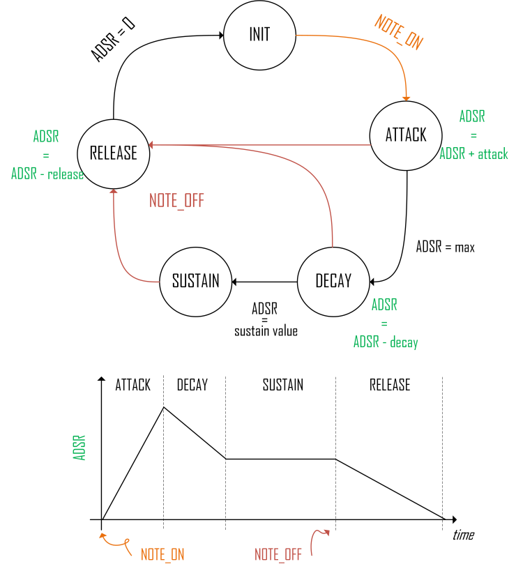
The ADSR (Attack, Decay, Sustain, Release) Amplitude Modulation Envelope is an essential component in any modern synthesizer which emulates the natural sound variation of musical instruments. The ADSR module is implemented as a VHDL block using a simple FSM (Finite State Machine), represented by the diagram below. The basic principle of this module is to use a varying counter to generate the envelope shape and to use it to modulate the voice output. The NOTE_ON event triggers the transition from the INIT state to the ATTACK state. In the ATTACH state, the counter is increased of a quantity proportional to the attack value. Right before the counter overflows, the FSM goes into the DECAY state. This time, the same counter is decreased of the decay value until the sustain value is reached. Once in SUSTAIN mode, the FMS waits the key to be released (NOTE_OFF event) to proceed in the RELEASE state. In the RELEASE state, the counter is decreased until it gets to zero. If the key is released before the SUSTAIN state is reached, the FMS will jump into the RELEASE state. The generated output counter is then multiplied by the signal coming out of the mixer block generating the final modulation.
Output filter
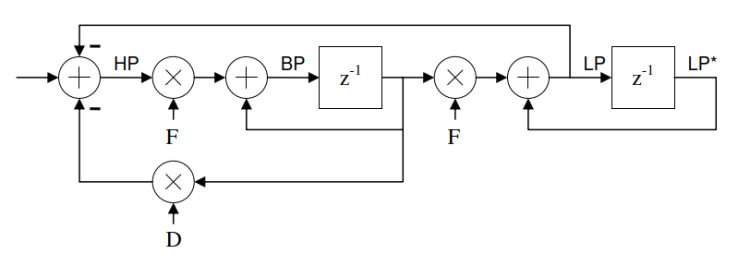
The output filter is considered by many people as the most critical component of a synthesizer. It defines ultimately its final frequency content and usually distinguishes one synth from another. Many different filtering architectures and techniques for audio applications have been developed in the past decades. All these share the common need of controlling Resonance and Cut-off frequency in an independent way. The topology chosen for the tiny synth project is a second order low pass SVF (State Variable Filter), a quite known architecture for audio engineers which was originally developed in analog. The equivalent digital state variable filter was described in Hal Chamberlin’s Musical Applications of Microprocessors. The figure below shows the digital implementation of the Chamberlin SVF filter. The Filter was developed in VHDL using signed arithmetic.
 The Chamberlin State Variable Filter
NCA
The NCA (Numeric Controlled Amplifier) is the last block in the voice signal path. It first scales the signal with respect to the key velocity and then it modulates the output signal using the NCA ADSR envelope signal. This is done by multiplying the signal by the velocity value (of ADSR signal) and normalizing it by shifting the result.
Resource utilization and conclusions
The figure below shows the resource utilization after synthesis reported by Vivado. It is not surprising that the most used resources are BRAM and DSP modules. In fact, the BRAM is heavily used for the DDS wavetables (no compression applied) while the DSPs are required for filter calculation and NCA. Obviously, these resources are proportional to the number of instantiated voices. These resources could be relaxed by using code optimization techniques as well as resource sharing.
As an example, the SVF stage designed in a parallel form and therefore requiring three DSP modules per voice (three multiplications) could be designed in serial by sharing one DSP module. This would result in a drop of DSP modules by 66%.
At the beginning of the project, I decided to explore the capabilities of the DDS as a synthesis method. The drawback of this approach is that it requires a significant amount of memory to store the wavetables. However, the same oscillators (except the sinewave) could be implemented using simpler combinational and sequential logic. This would result in a significant decrease in BRAM utilization despite an increase of FFs (Flip Flops).
 Resource utilization summary (Vivado)
The project explored the possibility to fully implement a subtractive synthesizer in an FPGA. At the time the project was started, there was no commercial FPGA-based synth available on the market. Today, the first FPGA-based synths have been introduced with the Novation PEAK and the Waldorf Kyra being the two main products. While the first is based on a hybrid approach (digital oscillators, analog filter) the Kyra seems to be the first full FPGA synth based on DDS and virtualization of analog filtering. What is clear is that FPGAs will definitely find a place in the market for digital synths.
Top Comments