


Table of Contents
Discontinued and Complex Button
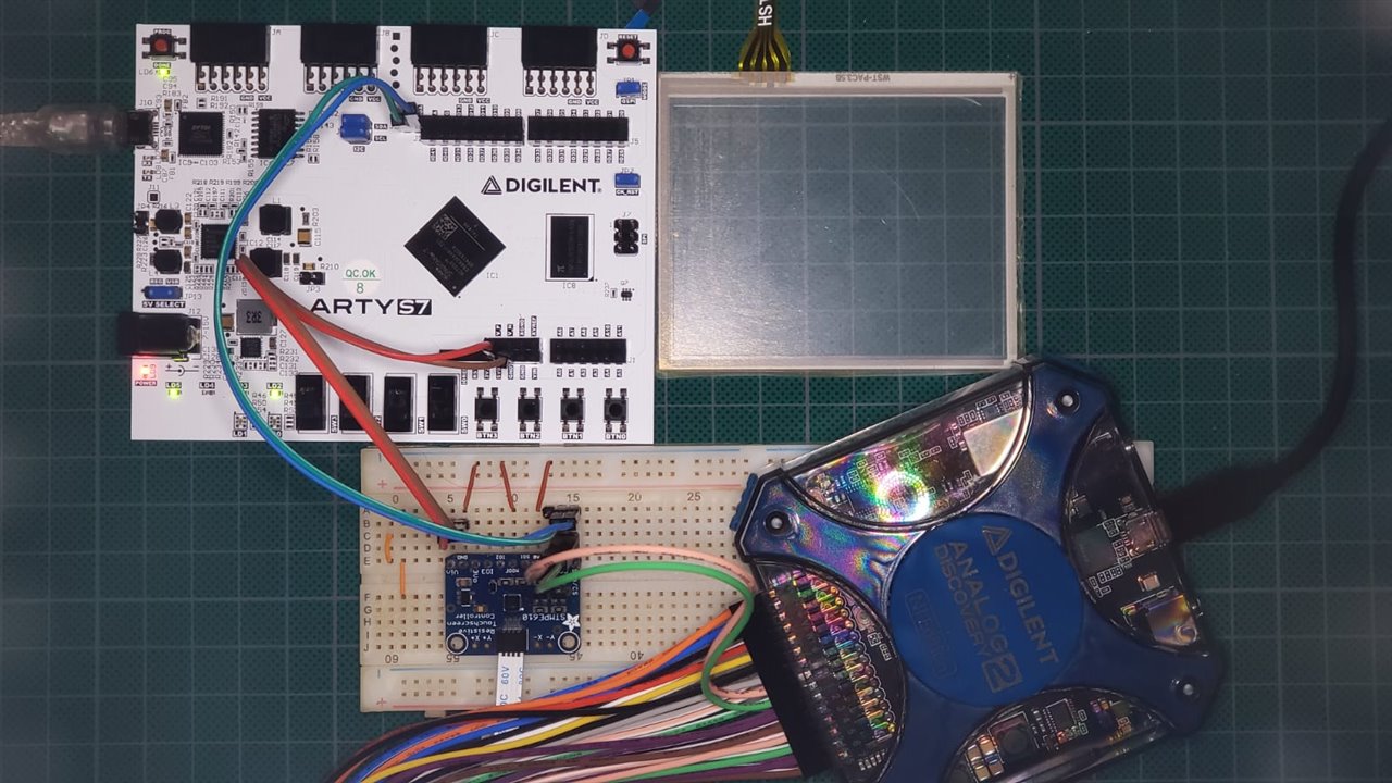
An Interesting sensor is a touch panel, but for this demo, I will use it in a very simple way.
The first point to made explicit is that used touch panel is based on resistive technology, illustrated in the following image,
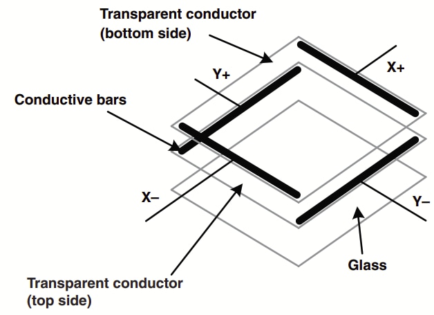
4-Wire Touch Screen Construction. Source: Texas Instruments
The use of this kind of component represents some challenges to integrate with our system without performance degradation. In order to solve that problem, an analog coprocessor is required to reduce the signal processing in the main system. There are two ways to do it: create a soft IP integrated into our system with minimal signal conditioning or use external hard IP with all the elements integrated into the chip (an ASIC).
The 4-wire panel signal conditioning is performed by the Resistive Touch Screen Controller - STMPE610 Adafruit’s module. Nowadays, this is a discontinued product, but it allows the use of a panel with minimal effort. The module has two integrated communication protocols, SPI and I2C, configurable by the MODE terminal, 1 and 0 respectively. To minimize the connections between the ARTY S7 and the module, the I2C protocol was selected.
The architecture designed has no support for the device, but VIVADO has an IP block for the use of this protocol,
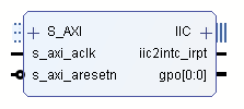
AXI IIC (2.0)
From Documentation, The LogiCORE(TM) IP AXI IIC Bus Interface connects to the AMBA® AXI specification and provides a low-speed, two-wire, serial bus interface to a large number of popular devices. This product specification defines the architecture, hardware (signal) interface, software (register) interface, and parameterization options for the AXI IIC Bus Interface module. This module can be interconnected to provide a new communication protocol for data and control information handling between the processor and external devices. This IP should be added to our architecture for system flexibility, consequently, the new block diagram is as follows,
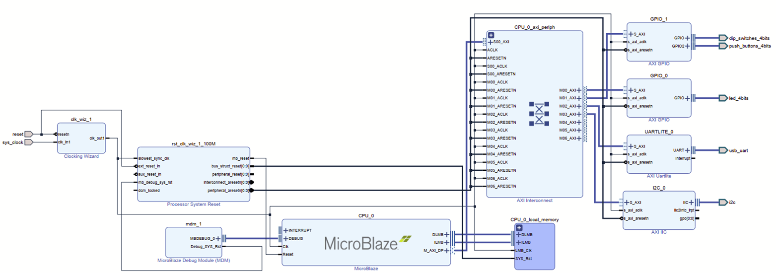
Arty S7 architecture with I2C support
Finally, the remainder process is solved by software. According to the device datasheet and Adrafruit's documentation, the following files were added to handle the STMPE610 IC,
#ifndef __STMPE610_H__
#define __STMPE610_H__

#include<stdint.h>

// Memory Map
#define CHIP_ID			0x00
#define ID_VER			0x02
#define SYS_CTRL1		0x03
#define SYS_CTRL2		0x04
#define INT_CTRL		0x09
#define INT_EN			0x0A
#define INT_STA			0x0B
#define ADC_CTRL1		0x20
#define ADC_CTRL2		0x21
#define TSC_CTRL		0x40
#define TSC_CFG			0x41
#define TSC_FRACTION_Z	0x56
#define FIFO_TH			0x4A
#define FIFO_CTRL_STA	0x4B
#define TSC_I_DRIVE		0x58

void STMPE610_Init(uint32_t PH_ADDR, uint32_t DEV_ADDR);
uint32_t STMPE610_isTouched(uint32_t PH_ADDR, uint32_t DEV_ADDR);

#endif
The STMPE610.h has the Memory Map of the analog co-processor and prototyping of useful functions.
#include "STMPE610.h"
#include "xiic_l.h"
#include "sleep.h"
#define SCRDLY 100000
uint32_t dataValue;
uint32_t command;
uint8_t *dataPtr;

void STMPE610_Init(uint32_t PH_ADDR, uint32_t DEV_ADDR){
	//RESET
	dataPtr = (uint8_t*)&command;
	dataPtr[0] = SYS_CTRL1;
	dataPtr[1] = 0x02;
	XIic_Send(PH_ADDR, DEV_ADDR, (uint8_t*)&command, 2, XIIC_STOP);
	usleep(SCRDLY);
	    //CLOCK ON
	    dataPtr[0] = SYS_CTRL2;
	    dataPtr[1] = 0x00;
	    XIic_Send(PH_ADDR, DEV_ADDR, (uint8_t*)&command, 2, XIIC_STOP);
	    usleep(SCRDLY);
	    //XYZ MODE
		dataPtr[0] = TSC_CTRL;
		dataPtr[1] = 0x01;
		XIic_Send(PH_ADDR, DEV_ADDR, (uint8_t*)&command, 2, XIIC_STOP);
		usleep(SCRDLY);
		//ADC1
		dataPtr[0] = ADC_CTRL1;
		dataPtr[1] = 0x50;
		XIic_Send(PH_ADDR, DEV_ADDR, (uint8_t*)&command, 2, XIIC_STOP);
		usleep(SCRDLY);
		//ADC2
		dataPtr[0] = ADC_CTRL2;
		dataPtr[1] = 0x02;
		XIic_Send(PH_ADDR, DEV_ADDR, (uint8_t*)&command, 2, XIIC_STOP);
		usleep(SCRDLY);
		//Config
		dataPtr[0] = TSC_CFG;
		dataPtr[1] = 0xA4;
		XIic_Send(PH_ADDR, DEV_ADDR, (uint8_t*)&command, 2, XIIC_STOP);
		usleep(SCRDLY);
		//Z
	    dataPtr[0] = TSC_FRACTION_Z;
	    dataPtr[1] = 0x06;
	    XIic_Send(PH_ADDR, DEV_ADDR, (uint8_t*)&command, 2, XIIC_STOP);
	    usleep(SCRDLY);
	    //FIFO_TH
	    dataPtr[0] = FIFO_TH;
	    dataPtr[1] = 0x01;
	    XIic_Send(PH_ADDR, DEV_ADDR, (uint8_t*)&command, 2, XIIC_STOP);
	    usleep(SCRDLY);
	    //FIFO_CTRL_STA
	    dataPtr[0] = FIFO_CTRL_STA;
	    dataPtr[1] = 0x01;
	    XIic_Send(PH_ADDR, DEV_ADDR, (uint8_t*)&command, 2, XIIC_STOP);
	    usleep(SCRDLY);
	    dataPtr[1] = 0x00;
	    XIic_Send(PH_ADDR, DEV_ADDR, (uint8_t*)&command, 2, XIIC_STOP);
	    usleep(SCRDLY);
	    //TSC_I_DRIVE
	    dataPtr[0] = TSC_I_DRIVE;
	    dataPtr[1] = 0x01;
	    XIic_Send(PH_ADDR, DEV_ADDR, (uint8_t*)&command, 2, XIIC_STOP);
	    usleep(SCRDLY);
}

uint32_t STMPE610_isTouched(uint32_t PH_ADDR, uint32_t DEV_ADDR){
	static _Bool touch;
	dataPtr[0] = TSC_CTRL;
	XIic_Send(PH_ADDR, DEV_ADDR,
			(uint8_t*)&command, 1, XIIC_REPEATED_START);
	usleep(SCRDLY);
	XIic_Recv(PH_ADDR, DEV_ADDR,
			(uint8_t*)&dataValue, 1, XIIC_STOP);
	usleep(SCRDLY);
	touch = dataValue & 0x80;
	return TRUE == touch;
}
The STMPE610.c contains all the definitions of the functions and probably function extensions. The code could be a bit cryptic but interesting. As you can see, if you want to reproduce the same behavior in your architecture you must validate the endianness of it. You must see a lot of dead times in the implementation, this was added to meet some timing constraints because I could not solve it at this time. In addition, those are useful for debugging.
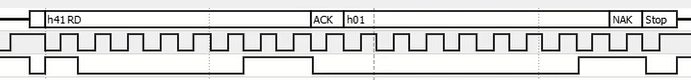
STMPE610 response when the touch is released
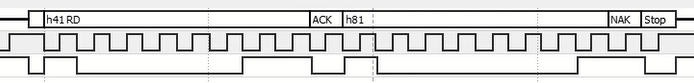
STMPE610 response when the touch is pressed
In the figures above, a query to the Touch Screen Controller Control Register (TSC_CTRL), located at address 0x40. This process is achieved by the STMPE610_isTouched() function, returning if the 8th bit is active. This means that the panel is touched.
#include <stdio.h>
#include <stdint.h>
#include "platform.h"
#include "sleep.h"
#include "GPIO.h"
#include "STMPE610.h"

#define IIC_BASE_ADDRESS	XPAR_IIC_0_BASEADDR
#define S_TOUCH_ADDRESS  	0x41

IP_GPIO_t volatile *const LEDS = (IP_GPIO_t*)XPAR_GPIO_0_BASEADDR;
IP_GPIO_t volatile *const INPUTS = (IP_GPIO_t*)XPAR_GPIO_1_BASEADDR;

typedef struct{
	uint32_t value: 4;
}nibble_t;

int main(void){

    init_platform();
    LEDS -> TRI1 = 0x00000000;
    nibble_t Q = {0};

    STMPE610_Init(XPAR_IIC_0_BASEADDR, S_TOUCH_ADDRESS);

    while(1){
    	if(STMPE610_isTouched(XPAR_IIC_0_BASEADDR, S_TOUCH_ADDRESS)){
    		if(INPUTS -> DATA2 & 0b0010){
    			Q.value = INPUTS -> DATA1;
    		}else{
				if(INPUTS -> DATA2 & 0b0100){
					Q.value++;
				}else{
					Q.value--;
				}
    		}
    	}
    	xil_printf("%02d\n", Q.value);
    	LEDS -> DATA1 = Q.value;
    	sleep(1);
    }
    cleanup_platform();
    return 0;
}
Only some lines were added and a condition was changed to test the touch panel as a button. In the future, the module could be changed or the software improved.
Own Quadrature Encoder Interface (QEI)
Project proposal
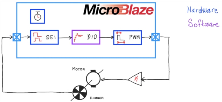
For the project proposal, it is required to sense the position and/or velocity of the motor. There are many ways to do it, but the common and preferred is the use of quadrature encoders. This is for sense, but in actuation it is needed a way to create a signal to manage power delivery to the motor. On one hand, the PWM channel has no problems because a Xilinx peripheral is available in the IP catalog and the programming model is easy to understand. On the other hand, there is not a peripheral that covers this in a direct way.
There are three events: clockwise count, counterclockwise, and index reset. Consequently, an own IP peripheral is created with configuration registers to handle both rotation directions with index reset, in case of the encoder has this additional channel, and positive logic or negative logic handling for this channel. Because some encoders have an active low index signal, this is required to detect the signal without additional circuitry. In addition, the peripheral has a register to count clock ticks to simulate a sampling time for differential positioning. This means that the register can obtain the velocity of the motor without additional calculations in the processor, consequently, the processor could act as a monitor because the velocity calculation is solved by hardware. Finally, this peripheral has three inputs, CH_A, CH_B, and CH_Z, and one output, interrupt. When the sampling time is met, an active high signal is triggered for interrupt handling.

Quadrature Encoder Interface with Interrupt signal
The peripheral Memory Map is shown below,
| Register | Meaning |
| sTicks | Sample time for velocity measure and interrup triggering |
| Configure | QEI configuration |
| Reserved | - |
| Reserved | - |
| Dummy | Register for device test |
| Status | State of input signals and internal registers |
| Velocity | signed 32-bit motor velocity register |
| Position | signed 32-bit motor position register |
Configure register are bit-maskable and has the next meaning,
| Bit | Meaning |
| 1 |
1 = Enable the index channel detection for position reset. 0= Disable the index channel detection |
| 0 |
1 = Active low logic for index channel 0 = Active high logic for index channel |
Status register are bit-maskable and has the next meaning,
| Bit | Meaning |
| 4 | A channel status |
| 3 | B channel status |
| 2 | Index channel status |
| 0 |
1 = clockwise rotation 0 = counterclockwise rotation |
To handle the interrupt, it is required an Interrupt Controllor, but it is available in Xilinx IP Catalog too. The new architecture is as follows,
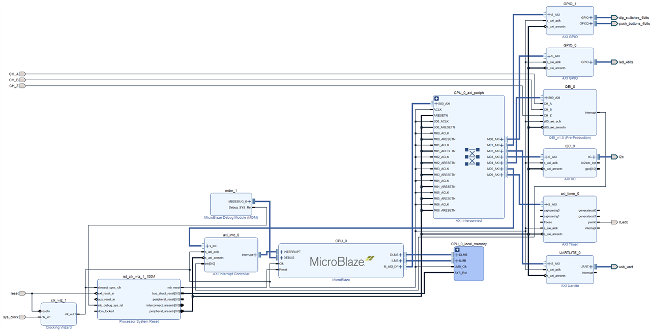
Digital Controller Architecture
The following is the QEI header files,
#ifndef QEI_H
#define QEI_H


/****************** Include Files ********************/
#include "xil_types.h"
#include "xstatus.h"
#include <stdint.h>

#define QEI_S00_AXI_SLV_REG0_OFFSET 0
#define QEI_S00_AXI_SLV_REG1_OFFSET 4
#define QEI_S00_AXI_SLV_REG2_OFFSET 8
#define QEI_S00_AXI_SLV_REG3_OFFSET 12
#define QEI_S00_AXI_SLV_REG4_OFFSET 16
#define QEI_S00_AXI_SLV_REG5_OFFSET 20
#define QEI_S00_AXI_SLV_REG6_OFFSET 24
#define QEI_S00_AXI_SLV_REG7_OFFSET 28


/**************************** Type Definitions *****************************/
typedef struct{
	uint32_t sTicks;
	uint32_t Config;
	uint32_t R2;
	uint32_t R3;
	uint32_t Dummy;
	uint32_t Status;
	int32_t Velocity;
	int32_t Position;
}QEI_t;

void EnableIndex(QEI_t *Dev);
void DisableIndex(QEI_t *Dev);
void IndexPositiveMode(QEI_t *Dev);
void IndexNegativeMode(QEI_t *Dev);
uint32_t setSampleTicks(QEI_t *Dev, uint32_t Ticks);
uint32_t getSampleTicks(QEI_t *Dev);
int32_t getPosition(QEI_t *Dev);
int32_t getVelocity(QEI_t *Dev);

/**
 *
 * Write a value to a QEI register. A 32 bit write is performed.
 * If the component is implemented in a smaller width, only the least
 * significant data is written.
 *
 * @param   BaseAddress is the base address of the QEIdevice.
 * @param   RegOffset is the register offset from the base to write to.
 * @param   Data is the data written to the register.
 *
 * @return  None.
 *
 * @note
 * C-style signature:
 * 	void QEI_mWriteReg(u32 BaseAddress, unsigned RegOffset, u32 Data)
 *
 */
#define QEI_mWriteReg(BaseAddress, RegOffset, Data) \
  	Xil_Out32((BaseAddress) + (RegOffset), (u32)(Data))

/**
 *
 * Read a value from a QEI register. A 32 bit read is performed.
 * If the component is implemented in a smaller width, only the least
 * significant data is read from the register. The most significant data
 * will be read as 0.
 *
 * @param   BaseAddress is the base address of the QEI device.
 * @param   RegOffset is the register offset from the base to write to.
 *
 * @return  Data is the data from the register.
 *
 * @note
 * C-style signature:
 * 	u32 QEI_mReadReg(u32 BaseAddress, unsigned RegOffset)
 *
 */
#define QEI_mReadReg(BaseAddress, RegOffset) \
    Xil_In32((BaseAddress) + (RegOffset))

/************************** Function Prototypes ****************************/
/**
 *
 * Run a self-test on the driver/device. Note this may be a destructive test if
 * resets of the device are performed.
 *
 * If the hardware system is not built correctly, this function may never
 * return to the caller.
 *
 * @param   baseaddr_p is the base address of the QEI instance to be worked on.
 *
 * @return
 *
 *    - XST_SUCCESS   if all self-test code passed
 *    - XST_FAILURE   if any self-test code failed
 *
 * @note    Caching must be turned off for this function to work.
 * @note    Self test may fail if data memory and device are not on the same bus.
 *
 */
XStatus QEI_Reg_SelfTest(void * baseaddr_p);

#endif // QEI_H
/***************************** Include Files *******************************/
#include "QEI.h"

/************************** Function Definitions ***************************/
void EnableIndex(QEI_t *Dev){
	Dev -> Config |= 0b10;
}

void DisableIndex(QEI_t *Dev){
	Dev -> Config &= ~(0b10);
}

void IndexPositiveMode(QEI_t *Dev){
	Dev -> Config &= ~(0b1);
}

void IndexNegativeMode(QEI_t *Dev){
	Dev -> Config |= 0b1;
}

uint32_t setSampleTicks(QEI_t *Dev, uint32_t Ticks){
	Dev -> sTicks = Ticks;
	return getSampleTicks(Dev);
}

uint32_t getSampleTicks(QEI_t *Dev){
	return Dev -> sTicks;
}

int32_t getPosition(QEI_t *Dev){
	return Dev -> Position;
}

int32_t getVelocity(QEI_t *Dev){
	return Dev -> Velocity;
}
Signal conditioning
Commonly, the encoders have 5V logic or more in the case of industrial encoders. So, it is required a level converter to manage the 5V signals in 3V3 FPGA signals. An Arduino proto shield is used to mount the circuitry for this purpose, considering open collector signal encoders.
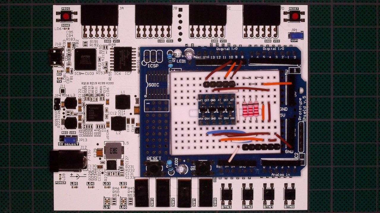
Signal conditioner mounted.
Data presentation
MPLAB Data Visualizer is used to present data. The simple protocol for data transmision and dashboard availability make feasible the use of this tool for quick data representation requiring two basic functions. The Header files are the following,
#ifndef __DATA_VISUALIZER_H__
#define __DATA_VISUALIZER_H__

#include <stdint.h>
#include <stdio.h>

#define DV_START	0
#define DV_END		1

void dvSendCode(uint8_t code, uint8_t mode);
uint32_t dvSendVar(void *var, size_t size);

#endif
#include "DataVisualizer.h"
#include "xparameters.h"
#include "xuartlite_l.h"

void dvSendCode(uint8_t code, uint8_t mode){
	XUartLite_SendByte(STDOUT_BASEADDRESS, mode? ~code: code);
}

uint32_t dvSendVar(void *var, size_t size){
	char *bData = (char*)var;
	static size_t i;
	for(i = 0; i < size; i++){
		XUartLite_SendByte(STDOUT_BASEADDRESS, *(bData + i));
	}
	return i;
}
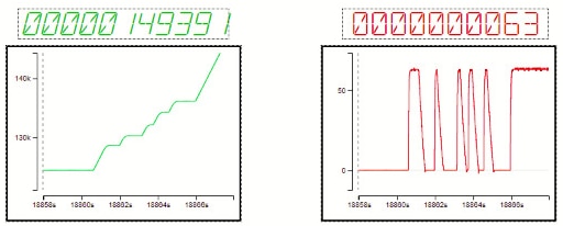
Data presentation demo for position and velocity in MPLAB Data Visualizer dashboard.
Links
https://github.com/adafruit/Adafruit_STMPE610
https://www.xilinx.com/products/intellectual-property/axi_iic.html
https://www.microchip.com/en-us/tools-resources/debug/mplab-data-visualizer