


For the 7 ways to leave your Spartan-6 FPGA program, I wanted to explore the use of Spartan-7 in an imaging system. I have some experience working with video streams on Zynq-7000 FPGAs (which I love!), but I never tried the same on Spartan series FPGAs. One motivation for this is that I have always felt that the Arm-9 cores on the Zynq-7000 consume a decent amount of power. While that is ok if you're making good use of the processor or if some extra power consumption is not an issue, but sometimes you're only using the processor for basic tasks like configuring peripherals, etc, and you really need to keep the power consumption to a minimum (think battery powered devices). In such cases, using a soft processor like microblaze should be a better option.
However, before we start running, we need to learn to walk first. Let's start with building a basic Microblaze system first. We will build a system with DDR3 RAM, since we will probably need a video buffer later.
Here we go...!
For this tutorial, I am using Vivado ML edition version 2022.1, which is the latest available tool version at the time of this writing (July, 2022).
We start with lauching Vivado. It takes a few seconds to open.
Next, we select "Create Project" and click "Next" on the first page of the New Project wizard.
On the next screen, choose an appropriate name for the project. I chose "Spartan7ImagingSystem" as I plan to build upon the same project in later steps. Also, choose a suitable project location. Personally I use a folder named "Xilinx_workspace" for all my Xilinx projects. Then click "Next"

On the next page we stick to the default "RTL project" option and click "Next".

On the next page ("Add Sources") we will not change anything and click "Next".

Same with "Add Constraints" page. We just click "Next" to move on.

On the next page titled "Default Part" first select "Boards" and then click "Refresh" to get the latest available boards from the Xilinx git repository. Thankfully, Arty-S7 is one of those boards, which will save us a lot of time later.

Once the board data finishes downloading, search for "Arty S7" and choose the appropriate version of your board. In my case I choose "Arty S7-50" as this is the board that I have. Then click "Next".

Finally we are presented with a summary of the options we have chose. Review and click "Finish"

At this moment, Vivado creates and opens our new project. First thing we need to do is create a new Block design. For this click the
On the left side of the screen, in "Project Manager" view, under "IP INTEGRATOR" click "Create Block Design"

The default options are good. Click OK

This creates and opens our new (empty) block design view.
For Microblaze designs using DDR memory, it is recommended to start with adding Memory Interface Generator (MIG). The easiest way to do that for Arty-S7 is to go to the "Boards" tab, and then dragging-and-dropping the "DDR3 SDRAM" into the main block design.

Press OK and you can see that a Memory Interface Generator (MIG) IP was added to the block design and automatically configured by Vivado. Don't run block automation yet.
Next we repeat the same with "DDR clock". This will also add a Clocking Wizard to the block diagram, running on the DDR clock.

Next, we select and Delete the "Clocking Wizard" as we will be feeding the 100MHz clock directly into the MIG.
Also, delete sys_clk_i and clk_ref_i on the input of the MIG. Then, connect the ddr_clock wo the sys_clk_i input of the MIG, and connect the ui_addn_clk_0 output of the MIG to the clk_ref_i input of the MIG. The block design should now look like this:

Next, we add Microblaze to the design. Click the "+" icon (Add IP) and search for microblaze. Double click to add it to block design.

Once the microblaze block is added to the design, we can run the Block Automation

This will open the settings for microblaze block. I used the following settings (changes to defaults are highlighted). Click OK afterwards.

This adds several IPs to the block design, and it should now look something like this:

We will also add a USB-UART by clicking Board -> USB UART and drag-dropping it to the main diagram.

Now, we can click "Run Connection Automation" and select the check box next to "All automation" in the dialog box that appears, and then click OK

This connects the system reset to the external reset input on the Arty-S7 board, among other things.
There is one input port on the MIG(device_temp_i) that is left unconnected and will give warning later. To avoid that, we can add a "Constant" IP with width of 12 and value of 0, and connect it to the device_temp_i port of the MIG, as following:

Our final block design looks as following:

We can validate our design by clicking the "Validate Design" icon to make sure there are no critical errors or warnings.

Next, we save the block design and then add a HDL wrapper to the block design by right-clicking "design_1" under Source -> Design Sources, and then selecting "Create HDL wrapper"

In the dialog box that appears, we let Vivado manage the HDL wrapper. Click OK

Once this process finishes, we can proceed to Synthesis, Implementation and generating bitstream.
Since we are using the Arty-S7 board data from Vivado, we actually don't need to add any constraint file for our current basic design, as default constraints are automatically added to the project. This is how Vivado knows what pins the inputs (eg clock, reset input ) and outputs (debug uart) are connected.
Under Flow Navigator, click "Generate Bitstream" and click OK on any dialog boxes that appear without changing anything. This will start the process of Synthesis, Implementation and finally generating bitstream. This can take several tens of minutes depending on your PC speed.
Once the process completes, a dialog box appars as following:

Click OK if you want to open the implemented design and look at things like reports (power, timing, resource utilization, etc). Or press cancel to proceed with the next steps.
At this point, we have generated our hardware design and need to handle the software part, for which we need to move to Vitis.
To export the generated hardware to Vitis, Click File -> Export -> Export Hardware

In the export hardware wizard, we will only change one option, to include bitstream in the exported design. Rest we can click Next/Finish till the end.

A progress bar will display and then disapper once the process is completed.
To open Vitis, click Tools -> Launch Vitis IDE

When Vitis Launches, it asks for workspace location. Click Browse and change the folder to same location as where we created the Vivado project. Then press "Launch".

Once Vitis opens, we can start creating new Application project. Usually we will create a "Platform project" first, but that can also be created as part of creating an Application project, so we take the shortest route here.
Click File -> New -> Application Project

The "New Application Project" Wizard opens. Press "Next" on the first welcome page.
On the next page, we can create the "Platform" for our application. Click "Create a new platform from harware (XSA)" -> Browse -> Navigate and select the .xsa file inside our main project directory. Then press "Open".

Press Next.
Give a name to the project and press Next

For the domain page, we keep the default options and click Next

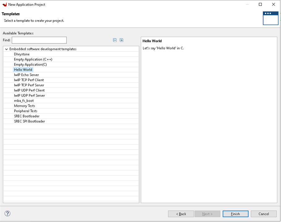
On the last page we are given option to choose from among several templates. We select the "Hello World" template and click Finish.
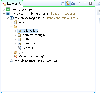
Vitis will take a bit of time to create the platform as well as the application project. Once this is done, we can see the two in the project "Explorer"
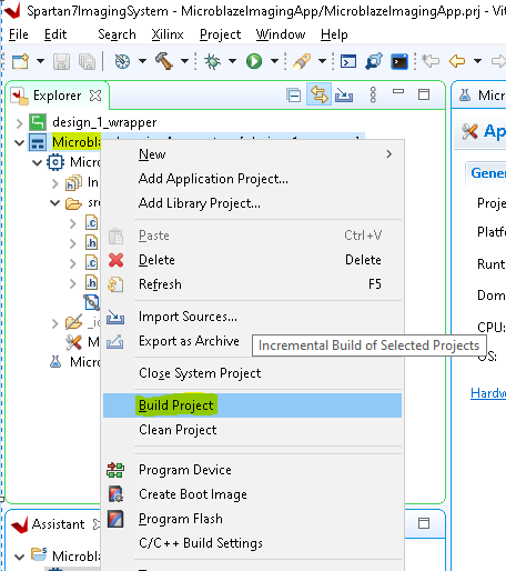
To build the newly created application project, right-click it and select "Build Project"
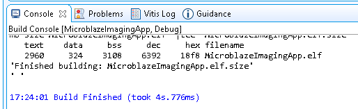
This should take less than a minute for this simple application. The progress can be monitured in the console window:
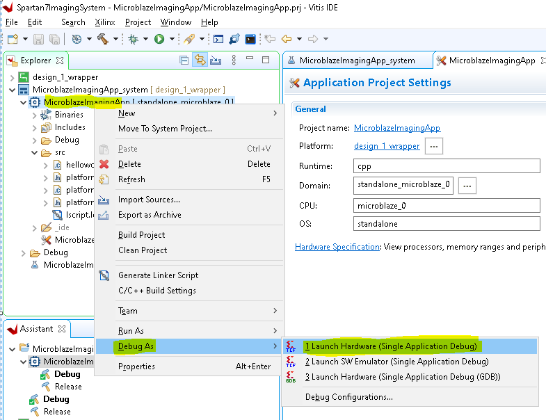
To launch the application on the Arty S7 boards, first make sure that the Arty-S7 board is connected via USB and powered up. Then, right-click <Application Name> -> Debug As -> Launch Hardware (Single Application Debug)
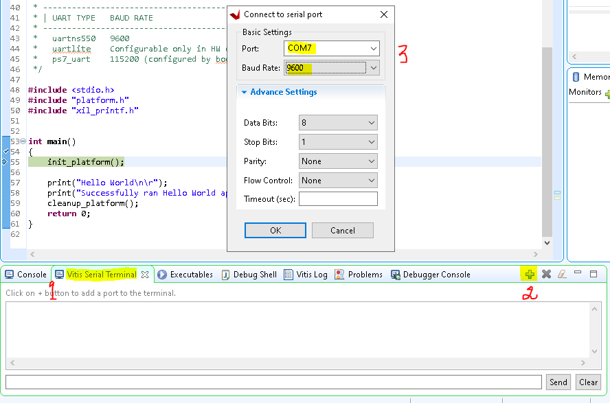
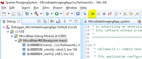
Vitis will switch to Debug view and upload the binaries to the FPGA. Once this is done, the application will halt at the first line of the application's main() function. This is a good opportunity to connect the Serial terminal to the serial port of the Arty-S7, as shown below (Make sure you use the COM port specific to your instance..in my case it was COM7):
Once this is connected, click the Resume icon in the top toolbar:
You should see the following messages in the Serial Console window:
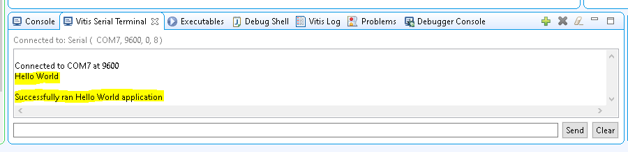
That's it. We have successfuly created and ran the first hello Microblaze application on our Arty S7 board.
In the next blog we will work on adding some video capabilities to our design. Thanks for reading!!


