


 Arty-S7-Rover (base architecture)
Disclaimer
Build a project with the Arty S7, 7 Ways to Leave Your Spartan-6 FPGA
challenge.
The Arty-S7-Rover is a small functional autonomous vehicle based on the Digilent Arty S7-50 board. The project was done for the 7 Ways to Leave Your Spartan-6 FPGA challenge.
All the files are open-source, MIT license and can be downloaded from ![]() -
-
Base Architecture
This second blog1 of four goes through the initial requirements (e.g. tools, build process) and the basic HDL for the Arty-S7-Rover project.
The base architecture implements the RISC-V core, the required memory banks and IO registers, a UART IP for serial port communications, a PWM block, and a simple firmware to test the setup by controlling the LEDs with user input from the buttons and dipswitch. All the RTL was implemented in SystemVerilog. Note that this project does not use Vivado IP Integrator, and all the HDL is FPGA vendor independent2.
Repository
The ![]() -
-
Getting the files
# Clone repository
mkdir -p ~/dev; cd ~/dev
git clone https://github.com/dramoz/arty-s7.git
#git clone git@github.com:dramoz/arty-s7.git (if SSH access enabled)

# Get submodule(s)
cd arty-s7
git submodule update --init --recursive

# RTL files
cd projects/arty_s7_atrover

# Firmware files
cd projects/arty_s7_atrover/vexriscv_generator/VexRiscvBase/
Directory structure
https://github.com/dramoz/arty-s7
├── 3Dmodels
├── arty-s7.code-workspace
├── assets
├── board
├── docs
├── LICENSE
├── projects
│   ├── arty_s7_atrover
│   │   ├── assets
│   │   ├── constrs
│   │   ├── docs
│   │   ├── README.md
│   │   ├── rtl
│   │   ├── spartan7_blog_experiments.md
│   │   ├── spartan7_blog_project.md
│   │   ├── spartan7_blog_sensor_actuator.md
│   │   ├── spartan7_blog_summary.md
│   │   ├── src
│   │   ├── tb
│   │   ├── tcl
│   │   ├── typescript
│   │   └── vexriscv_generator
│   └── arty_s7_test
└── README.md
Arty-S7 repository structure
➜ The vexriscv_generator submodule has the required setup to build up the FW and generate the custom VexRiscv for this project. The VexRiscv architecture used in this project is the VexRiscvBase. The VexRiscv is a submodule pointing to the VexRiscv GitHub project.
arty-s7/projects/arty_s7_atrover/vexriscv_generator
├── cpu_template
├── gen_vexriscv.sh
├── jtag.py
├── LICENSE
├── minVexRiscv
├── minVexRiscvJtag
├── minVexRiscv.ld
├── README.md
├── scripts
├── spinalhdl_example
├── VexRiscv
├── VexRiscvBase
│   ├── build
│   ├── build_fw.sh
│   ├── commands.sh
│   ├── cpu_layout.yaml
│   ├── gcc_riscv_args.md
│   ├── linker_sections.ld
│   ├── Makefile
│   ├── rtl
│   ├── spinalhdl
│   ├── src
│   ├── typescript
│   └── vexriscv_init.cfg
└── VexRiscvJtagAxi4
Arty-S7-Rover VexRiscv (FW) repository structure
Description
The Arty-S7-Rover is a semi-autonomous vehicle that uses a Xilinx Spartan-7/50 FPGA as its main processor. Inside the FPGA a RISC-V microprocessor was instantiated plus other RTL blocks to control the vehicle. Without too many details, the Arty-S7-Rover is built from three main blocks:
-
Hardware
-
Arty S7-50 development board
- RISC-V 32bits processor core + instruction/data memory
- IPs for IO control
-
3D printed chassis
- The required STL files are under the
arty-s7/3Dmodels/and not under the project subfolder.
- The required STL files are under the
-
Sensors & Actuators
- 2xDC motors
- Ultrasound range finder
- 10 DOF sensor
-
-
HDL
- Verilog/SystemVerilog RTL
- VexRiscv/SpinalHDL RISC-V microprocessor
-
Firmware
- RISC-V C/C++ code
The RISC-V microprocessor was selected as a challenge. Commonly, projects that required an embedded processor for a Xilinx Spartan device may use the Xilinx MicroBlaze Soft Processor Core, so I was curious about using a different softcore and testing the design flow with this project.
| {gallery}Arty S7 - Rover |
|---|
 |
 |
 |
 |
 |
Arty S7 Rover
Tools (+Setup)
All the development of the project was done in a ![]() VirtualBox VM running
VirtualBox VM running ![]() Ubuntu 20.04.4 LTS (Focal Fossa), on a
Ubuntu 20.04.4 LTS (Focal Fossa), on a  host computer with
 ![]() Windows11/Pro.
Windows11/Pro.
It should be possible to run the tools natively on a Ubuntu20.04 installation or on WSL2. A Linux distribution is required for RISC-V
Xilinx - Vivado
Download and install ![]() Vivado ML Edition 2022.1. The free edition is Spartan-7 friendly and does not require any license.
Vivado ML Edition 2022.1. The free edition is Spartan-7 friendly and does not require any license.
The drivers to program the Arty-S7 can be installed directly on the VM and use USB passthrough as shown in the picture below. However, in my particular setup, I installed Xilinx Lab Server on the host machine and connected the Vivado running from the VM.
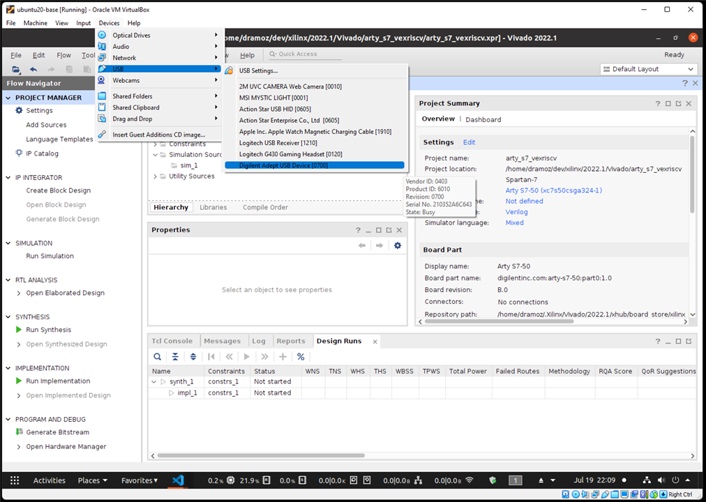
Ubuntu-VM USB passthrough

| {gallery}Vivado - Using a remote target |
|---|
|
|
 |
 |
 |
 |
 |

Vivado Remote Target
SpinalHDL / VexRiscv
The  used in this project (VexRiscv) was generated using SpinalHDL, a Scala-based HDL library.
# Install Scala
mkdir -p ~/tools; cd ~/tools
curl -fL https://github.com/coursier/launchers/raw/master/cs-x86_64-pc-linux.gz | gzip -d > cs && chmod +x cs && ./cs setup

# Generate a VexRiscv
cd ~/repos
git clone git@github.com:SpinalHDL/VexRiscv.git
cd ~/repos/VexRiscv/
sbt "runMain vexriscv.demo.GenFull"
➜ The VexRiscv used in this project is already generated and saved in the repository in the RTL directory.
The  dramoz/arty-s7 repository submodules the dramoz/vexriscv_generator repository, where the required files to generate the core processor and the firmware can be found.
RISC-V Toolchain (C/C++)
To compile the FW, download and install the prebuilt ![]() toolchain
toolchain
# Download toolchain
mkdir -p ~/tools; cd ~/tools
wget https://static.dev.sifive.com/dev-tools/freedom-tools/v2020.12/riscv64-unknown-elf-toolchain-10.2.0-2020.12.8-x86_64-linux-ubuntu14.tar.gz

# Extract and move to the installation directory
tar -xzvf riscv64-unknown-elf-toolchain-10.2.0-2020.12.8-x86_64-linux-ubuntu14.tar.gz
sudo mv riscv64-unknown-elf-toolchain-10.2.0-2020.12.8-x86_64-linux-ubuntu14 /opt/riscv64-unknown-elf-toolchain

# Update bash to add toolchain path
echo 'export PATH=/opt/riscv64-unknown-elf-toolchain/bin:$PATH' >> ~/.bashrc
source ~/.bashrc

# Test
riscv64-unknown-elf-gcc --version
> riscv64-unknown-elf-gcc (SiFive GCC-Metal 10.2.0-2020.12.8) 10.2.0
> Copyright (C) 2020 Free Software Foundation, Inc.
> This is free software; see the source for copying conditions.  There is NO
> warranty; not even for MERCHANTABILITY or FITNESS FOR A PARTICULAR PURPOSE.
Generating Verilog memory HEX file
To generate a compatible Verilog HEX file with the RISC-V firmware, it is necessary to convert it with ![]() elf2hex application.
elf2hex application.
# Clone repository elf2hex
mkdir -p ~/repos; cd ~/repos
git clone git://github.com/sifive/elf2hex.git

# Install elf2hex
cd elf2hex
autoreconf -i
./configure --target=riscv64-unknown-elf
make -j $(nproc)
sudo make install
Verification Tools

![]()

All the verification for this project was done using Open Source projects:
- Verilator is the fastest Verilog/SystemVerilog simulator.
- cocotb is a COroutine based COsimulation TestBench environment for verifying VHDL and SystemVerilog RTL using Python.
- GTKwave is a fully featured GTK+ based wave viewer for Unix, Win32, and Mac OSX which reads LXT, LXT2, VZT, FST, and GHW files as well as standard Verilog VCD/EVCD files and allows their viewing.
Other tools
Other tools used in this project
-
 Visual Studio Code SystemVerilog and C/C++ editor
TerosHDL plugin (for documentation generation)
-
 VirtualBox for Ubuntu20 on Windows11Pro
 -
 GNU Make for firmware/code elaboration and HW simulation.
 -
 TeraTerm or any other serial terminal.
The project
Top Level
The top-level block connects to:
-
Inputs
- DIP switches (4)
- Buttons (4)
- UART Rx
- Distance Sensor Echo Pulse
-
Outputs
- LEDs (2)
- RGB LEDs (2) - each one requires three inputs (red, green, blue)
- DC Motors PWM output (4)
- UART Tx
- Distance Sensor Trigger

Arty-S7-Rover top IO diagram

Arty-S7-Rover top dependency diagram
VexRiscv
The VexRiscv is a plugin-based HDL RISC-V core. For this project, a simple architecture was selected:
-
RV32IM
- 32-bit architecture
- Integer ALU plus multiplication and division
- 5-stage in-order pipeline
-
Simple instruction/data memory access (e.g. no cached)

Arty-S7 VexRiscv core IO diagram
Firmware
The firmware for the core processor is done in C++. As the FW is a bare metal implementation, it is necessary to implement some initialization code and define a proper link methodology. The FW build is done by make. After the riscv-toolchain is installed, building the FW is straightforward.
cd arty-s7/projects/arty_s7_atrover/vexriscv_generator/VexRiscvBase/
# make clean; script -c "MK_DBG=1 make"
./build_fw.sh
The Linker sections file and the Makefile are located in the same directory of the ./build_fw.sh script.
arty-s7/projects/arty_s7_atrover/vexriscv_generator/VexRiscvBase/src
├── cpu_layout.h
├── include
│   └── memory_map.h
├── macros.S
├── main.cpp
├── start.S
└── trap.cpp
Arty-S7-Rover Firmware
Core RAM

Arty-S7 VexRiscv RAM IO diagram
As the generated processor core does not have any memory instantiation, the instruction/data memory is created as a true dual-port RAM using Vivado Language Templates. The RAM is implemented with the following parameters, as required by the VexRiscv architecture:
-
True dual port, Write first w/ Byte-write
-
8192 Bytes
- 4096 instruction memory
- 4096 data memory
-
Low latency (e.g. not registered outputs): VexRiscv requires that memory access has only one clock latency.
Selecting the template:
-
Project Manager ˃ Language Templates-
Verilog ˃ Synthesis Constructs ˃ Coding Examples ˃ RAM ˃ BlockRAM ˃ True Dual PortTrue Dual Port ˃ 1 Clock ˃ Write First Mode w/ Byte-write
-

Vivado Language Templates
Instruction and data memory share the same memory block, where instruction access is read-only while data access is read/write (which would be useful if JTAG debug is implemented)
IO Peripherals
IO peripherals are handled by an IO Registers bank.
| # | Register | Remarks | Bits |
|---|---|---|---|
| 0 | DEBUG_REG | General purpose register for debugging (not connected to any IO port) | [31:0] |
| 1 | UART0_TX_REG | UART0 transmission register | [31]: Set to one to initiate the transmission, clear to zero when by HW indicating UART ready for next byte [7:0]: Byte to be transmitted |
| 2 | UART0_RX_REG | UART0 reception register | [31]: Poll bit indicating new byte available, clear to zero by HW after a read [7:0]: Byte to be transmitted |
| 3 | LEDS_REG | LEDs | [3:0] ↦LD[5:2] |
| 4 | RGB0_REG | RGB0 LEDs | [2:0] ↦ blue, green, red |
| 5 | RGB0_DCYCLE_REG | RGB PWM duty cycle [0, 20000] | RGBs are handled by a 20KHz PWM |
| 6 | RGB1_REG | RGB0 LEDs | [2:0] ↦ blue, green, red |
| 7 | RGB1_DCYCLE_REG | RGB PWM duty cycle [0, 20000] | RGBs are handled by a 20KHz PWM |
| 8 | BUTTONS_REG | Push buttons | [3:0] ↦ BTN[3:0] |
| 9 | SWITCHES_REG | DIP switch | [3:0] ↦ SW[3:0] |
| 10 | M0_BWD_PWM_REG | Motor 0 (left) backward PWM duty cycle | PWM frequency is set to 500 Hz |
| 11 | M0_FWD_PWM_REG | Motor 0 (left) forward PWM duty cycle | PWM frequency is set to 500 Hz |
| 12 | M1_BWD_PWM_REG | Motor 1 (right) backward PWM duty cycle | PWM frequency is set to 500 Hz |
| 13 | M1_FWD_PWM_REG | Motor 1 (right) forward PWM duty cycle | PWM frequency is set to 500 Hz |
| 14 | DISTANCE_REG | Ultrasound latest read. The RTL does a read every 1ms. | [31]: Set to one on a new read, clear by HW on FW read operation [30:0] Latest read value |
From the FW, the IO registers are accessed with:
// ----------------------------------------------------------------------
// --- __MEMORY_MAP__ ---
#ifndef __MEMORY_MAP__
#define __MEMORY_MAP__

#include<cstdint>

// ----------------------------------------------------------------------
uint32_t constexpr GPIO_BASE_ADDR = 0x80000000u;

#define SET_IO_REG(REG_INX, REG_NAME) volatile uint32_t* const REG_NAME = (uint32_t*)(REG_INX * 0x04 + GPIO_BASE_ADDR)
#define READ_IO(REG_ID) (*REG_ID)
#define WRITE_IO(REG_ID, VL) (*REG_ID) = VL

// Registers
SET_IO_REG( 0, DEBUG_REG      );
SET_IO_REG( 1, UART0_TX_REG   );
SET_IO_REG( 2, UART0_RX_REG   );
SET_IO_REG( 3, LEDS_REG       );
SET_IO_REG( 4, RGB0_REG       );
SET_IO_REG( 5, RGB0_DCYCLE_REG);
SET_IO_REG( 6, RGB1_REG       );
SET_IO_REG( 7, RGB1_DCYCLE_REG);
SET_IO_REG( 8, BUTTONS_REG    );
SET_IO_REG( 9, SWITCHES_REG   );
SET_IO_REG(10, M0_BWD_PWM_REG );
SET_IO_REG(11, M0_FWD_PWM_REG );
SET_IO_REG(12, M1_BWD_PWM_REG );
SET_IO_REG(13, M1_FWD_PWM_REG );
SET_IO_REG(14, DST_SENSOR_RD_REG );

// ----------------------------------------------------------------------
// --- __MEMORY_MAP__ ---
#endif
// ----------------------------------------------------------------------
Other blocks
PWM
The Pulse Width Modulation (PWM) block is a fixed/hard frequency variable duty-cycle RTL block.
////////////////////////////////////////////////////////////////////////////////
// Overview
// Generate PWM signal
////////////////////////////////////////////////////////////////////////////////

`default_nettype none

module pwm
#(
  parameter CLK_FREQ = 100000000,
  parameter PWM_FREQ = 20000,
  parameter WL = $clog2(CLK_FREQ/PWM_FREQ+1)
)
(
  input  wire           reset,
  input  wire           clk,

  input  wire  [WL-1:0] i_duty_cycle,
  output logic          o_pwm
);

  localparam unsigned PWM_MAX_CNT = int'(CLK_FREQ/PWM_FREQ);
  logic [WL-1:0] pwm_cnt;

  always_ff @( posedge clk ) begin : pwm_cnt_proc
    if (reset) begin
      pwm_cnt <= '0;
      o_pwm   <= 1'b0;
    end else begin

      if(pwm_cnt < PWM_MAX_CNT[WL-1:0]) begin
          pwm_cnt <= pwm_cnt + 1;
      end else begin
          pwm_cnt <= '0;
      end
      o_pwm <= (i_duty_cycle <= pwm_cnt) ? (1'b0) : (1'b1);
    end  // rst
  end // pwm_cnt_proc

endmodule: pwm

`default_nettype wire

PWM IO diagram
UART
The Universal Asynchronous Receiver-Transmitter (UART) is a simple/lite RTL block with a fixed/hard baud rate.
////////////////////////////////////////////////////////////////////////////////
// Overview
// Simple UART
////////////////////////////////////////////////////////////////////////////////

`default_nettype none

// Simple UART
module uart_lite
#(
    parameter BAUD_RATE=115200,
    parameter CLK_FREQUENCY=48000000,
    parameter DATA_BITS = 8,
    parameter RX_SAMPLES = 3
)
(
    input wire clk,
    input wire reset,

    // TX port
    output logic                 tx_rdy,
    input  wire                  tx_vld,
    input  wire  [DATA_BITS-1:0] tx_data,
    output logic                 tx_uart,

    // RX port
    output logic                 rx_valid,
    output logic [DATA_BITS-1:0] rx_data,
    input  wire                 rx_uart
);

localparam rcalc_CLKS_PER_BIT = $rtoi($ceil(CLK_FREQUENCY/BAUD_RATE));
localparam CLKS_PER_BIT_WL = $clog2(rcalc_CLKS_PER_BIT);
localparam CLKS_PER_BIT = rcalc_CLKS_PER_BIT[CLKS_PER_BIT_WL-1:0];

localparam TOTAL_BITS = 1 + DATA_BITS + 1;  // [START=0|DATA[0->T.BITS]|STOP=1]
localparam TOTAL_BITS_WL = $clog2(TOTAL_BITS);

localparam DATA_BITS_WL = $clog2(DATA_BITS);

// --------------------------------------------------------------------------------
logic [CLKS_PER_BIT_WL-1:0] tx_bit_baudrate;
logic   [TOTAL_BITS_WL-1:0] tx_bit_count;
logic    [TOTAL_BITS-1:0] tx_data_buff;

enum {TX_IDLE, TX_DATA_SEND} tx_fsm;
always_ff @(posedge clk) begin : tx_block
    if(reset) begin
        tx_rdy  <= 1'b1;
        tx_uart <= 1'b1;
        tx_fsm  <= TX_IDLE;

    end else begin
        case(tx_fsm)
            TX_IDLE: begin
                if(tx_vld) begin: if_tx_new_data
                    tx_rdy          <= 1'b0;
                    tx_bit_baudrate <= '0;
                    tx_bit_count    <= '0;
                    tx_data_buff    <= {1'b1, tx_data, 1'b0};

                    tx_fsm <= TX_DATA_SEND;
                end
            end

            TX_DATA_SEND: begin
                tx_uart <= tx_data_buff[tx_bit_count];

                if(tx_bit_baudrate < CLKS_PER_BIT) begin: if_sending_bit
                    tx_bit_baudrate <= tx_bit_baudrate + 1;

                end else begin: if_done_sending_bit
                    tx_bit_baudrate <= 'b0;
                    if(tx_bit_count < (TOTAL_BITS-1)) begin: if_more_bits_to_send
                        tx_bit_count <= tx_bit_count + 1;

                    end else begin: if_done_all_bits
                        tx_rdy <= 1'b1;
                        tx_fsm <= TX_IDLE;
                    end

                end
            end
        endcase
    end
end

// --------------------------------------------------------------------------------
localparam RX_SAMPLES_WL = $clog2(RX_SAMPLES);
localparam logic [CLKS_PER_BIT_WL-1:0] RX_SAMPLE_CLKS = CLKS_PER_BIT/(RX_SAMPLES+1);
localparam logic [CLKS_PER_BIT_WL-1:0] RX_LAST_SAMPLE_CLKS = CLKS_PER_BIT-RX_SAMPLES*RX_SAMPLE_CLKS;

logic [DATA_BITS_WL-1:0]  rx_bit_capture_cnt;
logic [RX_SAMPLES_WL-1:0] rx_bit_sample_cnt;
logic [RX_SAMPLES_WL:0]   rx_bit_curr_sample_value;

logic [CLKS_PER_BIT_WL:0] rx_next_sample_clks;
enum {RX_IDLE, RX_SAMPLING, RX_STORE_BIT_VL, RX_STOP_BIT} rx_fsm;

always_ff @(posedge clk) begin : rx_block
    if(reset) begin
        rx_valid <= 1'b0;
        rx_fsm   <= RX_IDLE;

    end else begin
        case(rx_fsm)
            RX_IDLE: begin
                rx_valid <= 1'b0;
                if(rx_uart==1'b0) begin: if_rx_new_capture
                    rx_bit_capture_cnt       <= '0;
                    rx_bit_sample_cnt        <= '0;
                    rx_bit_curr_sample_value <= '0;

                    rx_next_sample_clks <= CLKS_PER_BIT + RX_SAMPLE_CLKS;
                    rx_fsm              <= RX_SAMPLING;
                end
            end

            RX_SAMPLING: begin
                rx_next_sample_clks <= rx_next_sample_clks - 1;
                if(rx_next_sample_clks == '0) begin: if_sample_bit
                    rx_bit_curr_sample_value <= (rx_uart==1'b1)?(rx_bit_curr_sample_value+1):(rx_bit_curr_sample_value-1);

                    rx_bit_sample_cnt <= rx_bit_sample_cnt + 1;
                    if(rx_bit_sample_cnt==(RX_SAMPLES-1)) begin: if_bit_sample_done
                        rx_bit_sample_cnt        <= '0;
                        rx_next_sample_clks <= {1'b0, RX_LAST_SAMPLE_CLKS};
                        rx_fsm <= RX_STORE_BIT_VL;

                    end else begin
                        rx_next_sample_clks <= {1'b0, RX_SAMPLE_CLKS};
                    end
                end
            end

            RX_STORE_BIT_VL: begin
                rx_next_sample_clks <= rx_next_sample_clks - 1;
                if(rx_next_sample_clks == '0) begin: if_store_bit
                    rx_data[rx_bit_capture_cnt] <= (rx_bit_curr_sample_value[RX_SAMPLES_WL]==1'b0)?(1'b1):(1'b0);
                    rx_bit_curr_sample_value <= '0;

                    rx_bit_capture_cnt  <= rx_bit_capture_cnt + 1;
                    if(rx_bit_capture_cnt==(DATA_BITS-1)) begin
                        rx_fsm              <= RX_STOP_BIT;
                        rx_next_sample_clks <= {1'b0, CLKS_PER_BIT>>2};  // OK to exit before stop bit is done
                    end else begin
                        rx_fsm              <= RX_SAMPLING;
                        rx_next_sample_clks <= {1'b0, RX_SAMPLE_CLKS};
                    end
                end
            end

            RX_STOP_BIT: begin
                rx_next_sample_clks <= rx_next_sample_clks - 1;
                if(rx_next_sample_clks == '0) begin: if_end_stop_bit
                    rx_valid <= 1'b1;
                    rx_fsm   <= RX_IDLE;
                end
            end
        endcase
    end
end

endmodule: uart_lite

`default_nettype wire

UART IO diagram
Button debouncer
To avoid metastability on a button press an RTL block is connected between each FPGA button input and the RISC-V core. The debouncer block is a parametrizable block that generates a pulse (tick) after N ms of stable input, and also can detect user long button press. For the RISC-V reset, the debouncer is set to one second, so a long press is required to reset the processor. This is done to filter unwanted button presses.
/*
Module to give multiple functionalities to a user input (button) by different press/hold actions
- quick press: send system reset
- press and hold: send long_press
*/

`default_nettype none
module btn_debouncer #(
  parameter CLK_FREQUENCY = 100000000,
  parameter BUTTON_INPUT_LEVEL = 1,
  parameter CLICK_OUTPUT_LEVEL = 1,
  parameter CLICK_DEBOUNCE_MS = 10,
  parameter PRESS_OUTPUT_LEVEL = 1,
  parameter LONG_PRESS_DURATION_MS = 1000
)
(
  input wire reset,
  input wire clk,
  input wire usr_btn,
  output logic click,
  output logic press,
  output logic long_press
);
  // Reset logic
  logic [1:0] xor_path;
  localparam CLICK_CLKS = (CLICK_DEBOUNCE_MS==0) ? (1) : ($rtoi($ceil(CLK_FREQUENCY/1000*CLICK_DEBOUNCE_MS)));
  localparam LONG_PRESS_CLKS = (LONG_PRESS_DURATION_MS==0) ? (10*CLICK_CLKS) : ($rtoi($ceil(CLK_FREQUENCY/1000*LONG_PRESS_DURATION_MS)));
  localparam BOOT_CNT_WL = $clog2(LONG_PRESS_CLKS);
  logic [BOOT_CNT_WL-1:0] boot_counter = '0;

  // Send proper rst
  assign click = (boot_counter==CLICK_CLKS[0+:BOOT_CNT_WL]) ? (CLICK_OUTPUT_LEVEL) : (~CLICK_OUTPUT_LEVEL);
  assign press = (boot_counter>=CLICK_CLKS[0+:BOOT_CNT_WL]) ? (PRESS_OUTPUT_LEVEL):(~PRESS_OUTPUT_LEVEL);
  assign long_press = (boot_counter>=LONG_PRESS_CLKS[0+:BOOT_CNT_WL]) ? (PRESS_OUTPUT_LEVEL):(~PRESS_OUTPUT_LEVEL);

  always_ff @( posedge clk ) begin
    if(reset) begin
      xor_path     <= '0;
      boot_counter <= '0;

    end else begin
      xor_path <= {xor_path[0], usr_btn};
      if(^xor_path) begin
        boot_counter <= '0;
      end else begin
        if(xor_path[1]==BUTTON_INPUT_LEVEL) begin
          if(boot_counter <= LONG_PRESS_CLKS[0+:BOOT_CNT_WL]) begin
            boot_counter <= boot_counter + 1;
          end
        end else begin
          boot_counter <= '0;
        end // if/else but_pressed
      end // if/else (^xor_path)
    end // if/else reset
  end // alwasy_ff

endmodule: btn_debouncer

`default_nettype wire

Button Debouncer IO diagram
Simulation
The simulation of the project is handled by make and is done with the aid of CoCoTB/Verilator.
- CoCoTB provides the capability of implementing the testcases in Python
- Verilator is a really fast SystemVerilog simulator (as fast as it can get)
Running a simulation includes three steps:
- Generating the firmware HEX files
- Running CoCoTB
- Opening the generated wave with GTKwave.
Speeding up the simulation
As the HDL has several PWMs and a UART which run at lower frequencies (e.g. 20KHz), the simulation time required to run a test becomes prohibited. One trick is to define in the top level of the RTL a set of local parameters that can be selected between a simulation or an implementation. With this aid, PWM and UART frequencies are set to higher values and the required simulation time is acceptable.
Implementation
Resource utilization
The full implementation of the base architecture used:
| Block | LUTs (32600) | Registers (65200) | Block RAM (75) | DSPs (120) |
|---|---|---|---|---|
| arty_s7_atrover (top) | 1922 (5.90%) | 1916 (2.94%) | 9 (12.00%) | 4 (3.33%) |
| VexRiscv-RAM | - | - | 8 (10.67%) | - |
| VexRiscv | 1708 (5.24%) | 1056 (1.62%) | 1 (1.33%) | 4 (3.33%) |
A full utilization report can be found in Base Architecture Utilization Report
| {gallery}My Gallery Title |
|---|
 |
 |
 |
 |
Base Architecture Implementation Reports & Floorplan (Vivado)
Downloading and testing the implementation
Of all the project sections, this was probably the easiest and straight forward action. Plug-and-play - just connect the Arty-S7 to the USB port, open the Vivado Hardware manager and program the device.
Final Remarks
Although simple, the described base project demanded a lot of work on different fronts. The Xilinx Vivado tools were pretty much straightforward, with only minor inconveniences with constraints files and IO ports declaration, but just to be clear I came with previous experience with this tool and FPGAs.
On the RISC-V, the learning curve was harder. Doing a bare metal implementation required a lot of learning on two different fronts.
- Compiling required some adjustments to a new architecture, but in general, it was just C/C++
- Linking was more of a challenge. Some previous experience with microcontrollers helped, but nowadays with new frameworks like Arduino, Raspberry or Xilinx Zynq Ultrascale - all this complexity tends to be hidden from the final user. However, it was a really neat learning experience.
