


The 25LC256 SPI EEPROM needs some management, if you plan to write data to it. It's described in this app note. At startup, it's read-only. You need to enable write functionality and remove write protect. Once that's done, you can use the write functionality.
This is the sequence: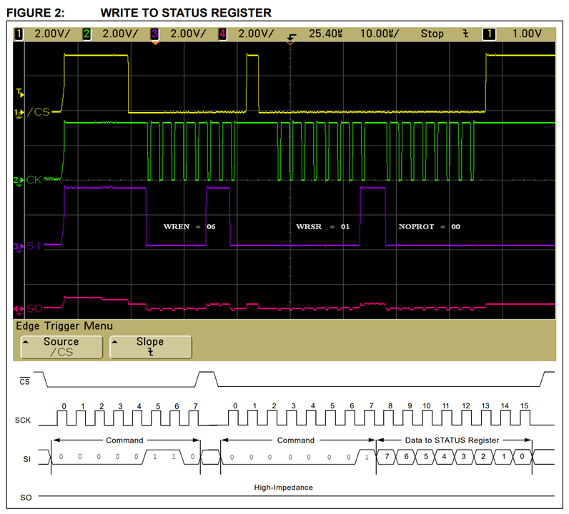
I need to send the 8 bit write-enable, then the 16 bit no-protection. Both should be wrapped inside a ~CS envelope.
I'm implementing the EEPROM VHDL as a state machine. Init at startup, then read, then wait for data and write. Once data is received and written, back to read. Because I'm managing the ~CS myself via bitbanging*, I'd like to keep each SPI sentence (a section wrapped inside a ~CS) as a state. So I split the init state in two:
- initialise Write Enable
- initialise No Protection
|
* The SPI module I selected doesn't support CS hold. It will hold CS low until the requested data size is sent. But that's a fixed size. The EEPROM has requirements to hold the CS until a activity is completed. In my case, that can be 1 byte for the WREN instruction, 2 bytes to write to a register, or 4 bytes to read/write data: instruction, 2 byte address, data. To get support for CS hold, I can:
I chose the 3rd option. |
My state machine will look like this:
- init WREN, then next
- init NOPROT, then next
- READ data from address, then next
- wait for data and WRITE to address, then 3
Here's the design. I tried to implement 1 and 2. The others just contain comments of what I think they 'll need to do:
architecture Behavioral of eeprom is
  TYPE FSM IS(init_wren, init_noprot, accept, read); --state machine
  SIGNAL state : FSM;
  SIGNAL step : integer range 0 to 5;

begin

  PROCESS(clk, reset_n)
  BEGIN
    IF(reset_n = '0') THEN --reset everything
      state <= init_wren;
      step <= 0;
      bitbang_cs_n <= '1';
      start <= '0';
    ELSIF(rising_edge(clk)) THEN
      case state is

        when init_wren => -- init eeprom, enable writing
          if (step = 0) then -- send WREN cmd
            bitbang_cs_n <= '0';
            step <= 1; -- next step
            data_out <= "00000110"; -- WREN (0x06)
            start <= '1';
          elsif (step = 1) then -- wait for ack from spi
            if (busy = '1') then  -- wait for spi buzy
              step <= 2;
            end if;
          elsif (step = 2) then -- finalise WREN
            if not (busy = '1') then  -- wait until spi no longer buzy
              -- finished
              start <= '0';
              state <= init_noprot;
              step <= 0;
              bitbang_cs_n <= '1';
            end if;
          end if;

        when init_noprot => -- init eeprom, no write protect
          if (step = 0) then -- write status register (0x01)
            bitbang_cs_n <= '0';
            step <= 1; -- next step
            data_out <= "00000001"; -- WRSR (0x01)
            start <= '1';
          elsif (step = 1) then -- wait for ack from spi
            if (busy = '1') then  -- wait for spi buzy
              step <= 2;
            end if;
          elsif (step = 2) then -- finalise WRSR
            if not (busy = '1') then  -- wait until spi no longer buzy
              -- finished
              start <= '0';
              step <= 3;
            end if;
          elsif (step = 3) then -- finalise WRSR
              step <= 4; -- next step
              data_out <= "00000000"; -- NOPROT (0x00)
              start <= '1';
          elsif (step = 4) then -- wait for ack from spi
            if (busy = '1') then  -- wait for spi buzy
              step <= 5;
            end if;
          elsif (step = 5) then -- finalise NOPROT
            if not (busy = '1') then  -- wait until spi no longer buzy
              -- finished
              start <= '0';
              state <= read;
              step <= 0;
              bitbang_cs_n <= '1';
            end if;
          end if;

        when read =>
          -- todo read from address
          -- todo READ cmd
          -- todo send address
          -- todo receive data

          -- finished
          state <= accept;
          step <= 0;

        WHEN accept =>
 		  IF not (data_in (3 downto 0) = "0000") THEN
			-- todo write to address
          -- todo WRITE cmd
          -- todo send address
          -- todo send data

			-- finished
			state <= read;
            step <= 0;
          END IF;

      END CASE;
    END IF;
  END PROCESS;

end Behavioral;
I think I'll have an issue with my CS bitbanging, as currently implemented. The state machine runs on a fast clock. The time between setting CS high and back low, between states, may be too short for the 25LC256. I know how to deal with that, but want to see if it's a real issue first.
edit: this works. See the comments below for the steps from fail to success...
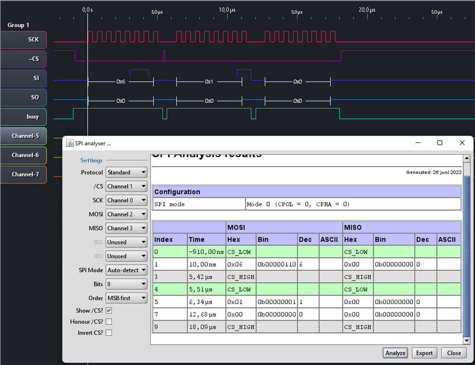
checkpoints:
- CS low
- send 0x06
- CS high
- min 350 ns before next step: 9 µs (I check this specifically, because I'm bitbanging this signal. All others controlled bt the SPI IP).
- CS low
- send 0x01
- send 0x00
- CS high
