Introduction
As part of the 7 Ways to Leave Your Spartan-6 FPGA roadtest, I have been exploring sensors that can be connected to the Arty-S7 for audio applications. For the current project, I am focussing on the following sensors
- Pmod I2S2 - Used to transmit and receive stereo audio signals through I2S protocol
https://digilent.com/reference/pmod/pmodi2s2/start - Pmod Color - a color sensor module with the ability to sense red, green, blue and clear light.
https://digilent.com/shop/pmod-color-color-sensor-module/ - Pmod CDC1 - 12-bit capacitance-to-digital converter (CDC)
https://digilent.com/reference/pmod/pmodcdc1/reference-manual
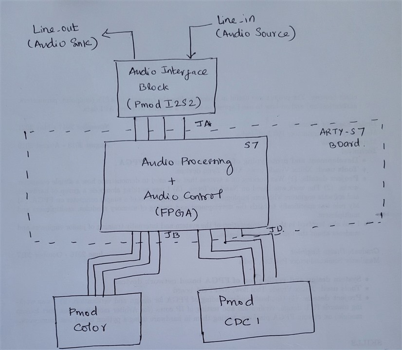
Top level block diagram (Final implementation):
You can find below the top level sketch for my final design that I am planning to implement. The design involves three main blocks

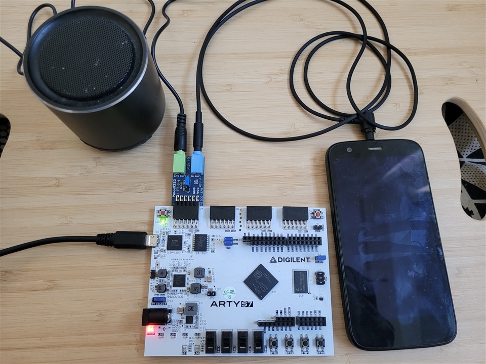
The actual hardware testbed will look like below

Audio interface block:
The main responsibility of the block is to receive the audio input from a audio source through the line in, and send the audio output to the output speaker through the line out. The Pmod I2S2 is the core member of the audio interface block.
Audio processing block:
The audio processing block can implement features to do audio synthesis (generation of new sounds) and audio effects (volume control, filtering, distortion, pitch effects, reverb). FPGA in the Arty-s7 board will form the central part of the audio processing system.
Audio control block:
The audio control block is responsible for controlling the functions of the audio processing block based on the sensor input (Pmod Color or Pmod CDC1).
In case of the Pmod Color, based on the colour sensed by the color sensor, decision can be made on how to control the audio processing block. Similarly, for Pmod CDC1, based on which of the two button are pressed, we can implement certain control on the audio processing block. The Pmod sensors by themselves are only capable of generating signals/data, these data needs to be interpreted (by the FPGA/Microblaze) based on certain thresholds (colour or capacitance) to finally control the audio block. This interpretation can be purely done inside the FPGA using hardware blocks or using software programs on Microblaze processor.
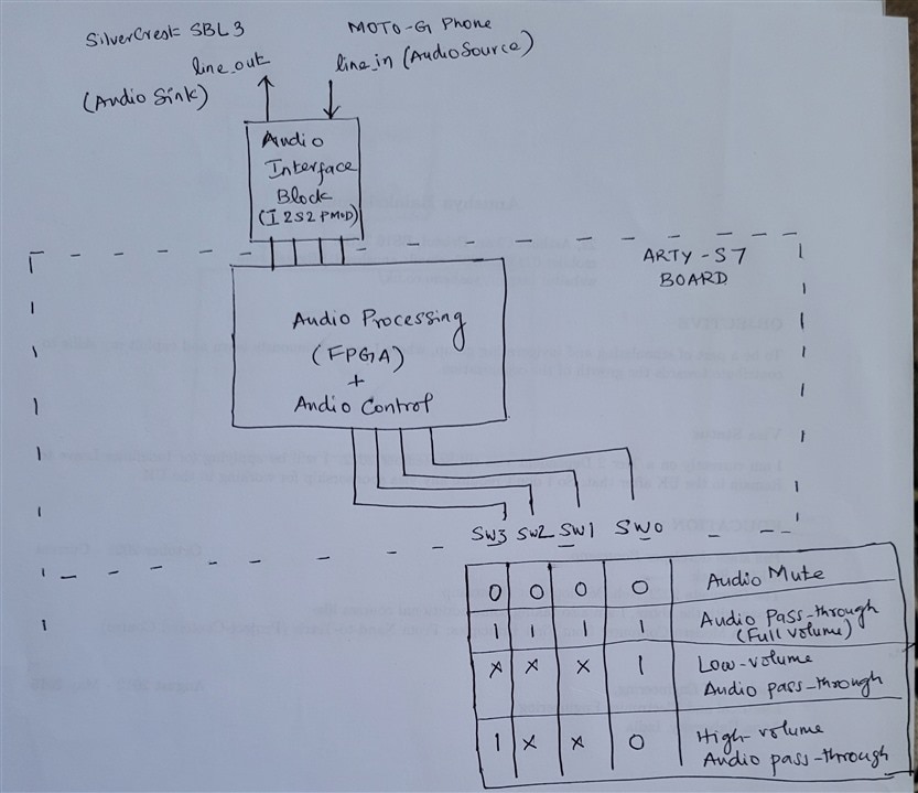
Top level block diagram (Current Simple implementation):
As you might have recognized from the above section, the design can become quite complex considering the design and verification aspects. In order to test Arty-s7 and the Pmod-I2S2, I implemented a simple design that was based on the example design from Digilent.
https://github.com/Digilent/Pmod-I2S2
Below is the top level sketch and the actual test setup.


A simplified form of the design (as a vivado IP) will be updated in the following area (tbd)
manihatn/fpga_projects: Place holder for fpga projects (github.com)
Audio interface block:
The audio input is received from a audio source (Moto G Mobile phone) through the line in, and send the audio output to the output speaker (SilverCrest SBL 3) through the line out. The Pmod I2S2 is the core member of the audio interface block.
Audio processing block:
For simplicity, the audio processing block implements volume control module. When the volume is high the design appears a simple audio pass-through and when the volume is low, the audio is muted. This is verified using sound level monitor app on Samsung S20 mobile
Audio control block:
The audio control block is implemented through the switches on the Arty-s7 board. When all the switches are low, the audio output is muted, when you set each of the switch to high, the volume gradually increases and finally reaches maximum volume when all the switches are turned high.
Demo:
You can find a short demonstration of the simplified audio processing on Arty-S7 below
More updates to follow hopefully soon.
