


1. Introduction
In this article, we will install PYNQ in Ubuntu 22.04 and then I will show you how to do a simple LED blinking using Python in PYNQ.
2. Installing PYNQ in KV260
The Xilinx/Kria-PYNQ is the main repository for everything related to PYNQ and you can find the repo here: Xilinx/Kria-PYNQ: PYNQ support and examples for Kria SOMs (github.com)
In there, they basically say that you can run the following commands to get PYNQ set up and running on your Ubuntu.
# cd into your preferred directory
# for my case, I am clonning the repo here: ~/work
git clone https://github.com/Xilinx/Kria-PYNQ.git
# cd into the clonned directory
cd Kria-PYNQ/
# install according to your system
# KV260: sudo bash install.sh -b KV260
# KR260: sudo bash install.sh -b KR260
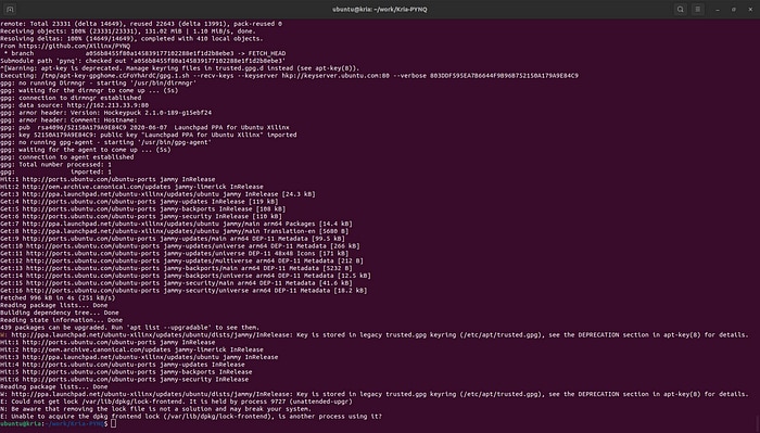
sudo bash install.sh -b { KV260 | KR260 } During this step, if you encounter an error that says something like what is shown in the Figure 1 — this is happening because Ubuntu, by default, checks for updates daily and installs them — then you need to either wait for the update process to be completed or disable the automatic system update and then restart your device. Check [1] and [2].
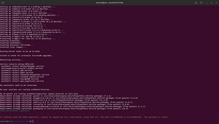
When everything is properly installed, you will get a message as shown in Figure 2.
3. Connecting external LED
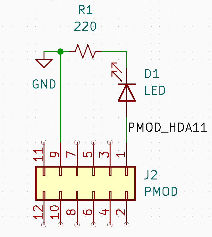
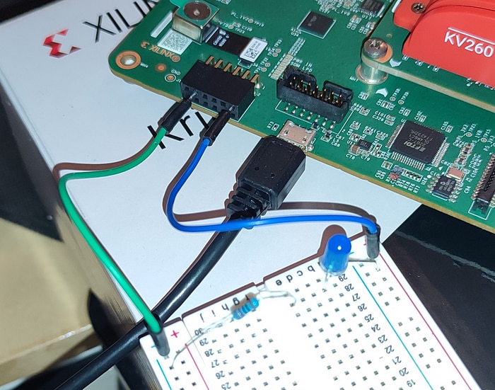
Kria KV260 does not have an on-board that could be accessed through the Programmable Logic (PL) side of the device. Therefore, we will have to connect an external LED to one of the PMOD pins. I have connected a blue LED in series with 220 Ohm resistor to the first pin of the PMOD connector. I have used the pin 9 as the GND end. Figure 3 shows the circuit diagram that I have used to connect the LED and resistor (PMOD in the KV260 carrier board is oriented as shown in the schematic). Figure 4 shows that actual picture of the connection.
Here’s the actual picture of my connection.
I referenced the PMOD schematic in Figure 3 from the KV260 datasheet and the complete connection, if you want to take a look quickly, is in Figure 5.
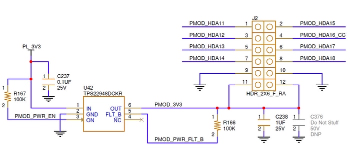
Following are how the pin labels are mapped to the actual pins in the FPGA.
Pin |     Label       |  Physical Pin
--------------------------------------
 1  |   PMOD_HDA11    |      H12
 2  |   PMOD_HDA15    |      B10
 3  |   PMOD_HDA12    |      E10
 4  |   PMOD_HDA16_CC |      E12
 5  |   PMOD_HDA13    |      D10
 6  |   PMOD_HDA17    |      D11
 7  |   PMOD_HDA14    |      C11
 8  |   PMOD_HDA18    |      B11
 9  |      GND        |       -
10  |      GND        |       -
11  |     PMOD_3V3    |       -
12  |     PMOD_3V3    |       -
For more information, you could refer to the KV260 constraint (xdc) file — which, by the way, I could find nowhere — or here: Programming the Kria KV260 FPGA with Vivado ML (Part 2) | TomoSoft.
4. FPGA programming using PYNQ
I have provided two examples: turning the led on and blinking the led. In the following GitHub page, you will find all files that are used here. They all have the same name but different extension, for example: led_on_block.bit, led_on_block.tcl, led_on_block.hwh
GitHub Link: rajivbishwokarma/kv260_led_blink
All these three files are required and have to have the same name. These are needed because:
a. <design>.bit : This is a binary configuration data needed for the FPGA. Vivado generates this by synthesizing and implementing the HDL code. In the most basic form, a bitstream (.bit) file tells the FPGA how to configure its internal logic and interconnects to implement the given hardware design.
b. <design>.tcl : The tcl file sets up the configuration environment for the FPGA. It provides information about the FPGA, including memory map, I/O pins, clockding and any other hardware-specific details.
c. <design>.hwh : This is a hardware handoff file with information on hardware design, including address map, memory locations and so on. This file is used by PYNQ to verify that the FPGA is properly configured to access resources.
5. Turning on the LED using PYNQ
The first design is extremely simple. When you load this design into the FPGA, all it does is just turn the LED on. This simple example will allow us to understand the basics of how we load the hardware into the FPGA using PYNQ.
5.1 Understanding the hardware design
If you take a look at the block diagram in Figure 6, you can observe that all it contains is an RTL block connected to the Zynq processing system. The connection to the Zynq is done purely because an Overlay cannot be written to the FPGA fabric without a connection to the Zynq. If you observe the Verilog code in Code Listing 1, you will see that an output is declared and assigned a value of ‘1’ and that is it. Even though a system clock is defined, it’s not used.
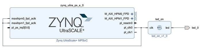
/* Code Listing 1 - Verilog code for turning the LED on. */

module led_on ( input clk, output led );
    assign led = 1'b1;
endmodule
5.2 Writing the bitstream to the FPGA
If you have connected Kria to the same network, then you can access the Jupyter Lab through your browser by going to: kria:9090/lab. It will open the Jupyter Lab and the default password is: xilinx.
Once you log in, you can create a new notebook and you can upload the downloaded files in the same folder (or any other).
Then, with the following code shown in Code Listing 2 can be run to load the design into the FPGA.
# Code Listing 2 - Writing the bitstream/overlay to the FPGA

from pynq import Overlay
overlay = Overlay('led_on_block.bit')
When the execution completes, the LED turns on.
6. Blinking the LED
The block design for blinking the LED is almost similar to the one for turning it on with the difference in the RTL code. Figure 8 and Figure 6 are almost identical, except for the code for the RTL module.
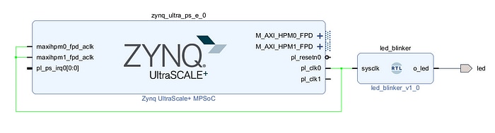
In Code Listing 3, you can see the Verilog design for the blinking the LED. As you might have already noticed, we actually utilize the system clock connected to the processing system (PS). The frequency for the clock provided to the programmable logic (PL) is 100 MHz, so that is what will be used.
/* Code Listing 3 - Verilog code for blinking the LED. */

module led_blinker
#(parameter REF_CLK=100000000)
(
    input       sysclk,
    output      o_led
);
    reg         r_led = 1'b0;
    integer     r_count = 0;

    /* Led control block */
    always @(posedge sysclk) begin
        if (r_count < REF_CLK) begin
            r_count <= r_count + 1;
        end else begin
            r_count <= 0;
            r_led   <= ~r_led;
        end
    end

    /* Output control */
    assign o_led = r_led;

endmodule
In this code, we are basically counting the ticks from the input clock and flipping the value of output (o_led) as soon as the count equals the frequency of the clock. Basically, we are turning the led on for 1 second and turning off for another 1 second.
Go ahead and upload the three files: ledblink.bit, ledblink.tcl, and ledblink.hwh to your Jupyter Notebook/Lab and then run the code provided in Code Listing 4.
# Code Listing 4 - Writing LED blinking bitstream to the FPGA

from pynq import Overlay
overlay = Overlay('ledblink.bit')
As soon as the code completes execution, the LED will start blinking, as shown in Figure 8.

To conclude, they say that blinking the LED is the hardware equivalent of saying “hello world” in a software programming language. Today, we blinked a LED in the PYNQ environment, so we just said hello world to KV260 PYNQ world!
References
[2] https://itsfoss.com/could-not-get-lock-error/
[3] Programming the Kria KV260 FPGA with Vivado ML (Part 2) | TomoSoft
[4] https://pynq.readthedocs.io/en/v2.0/overlay_design_methodology/overlay_tutorial.html
[5] https://discuss.pynq.io/t/tutorial-creating-a-hardware-design-for-pynq/145
[6] https://www.hackster.io/whitney-knitter/pmod-ip-development-for-kria-kv260-using-vitis-hls-069968

