element14 Community
element14 Community
    Register Log In
  • Site
  • Search
  • Log In Register
  • About Us
  • Community Hub
    Community Hub
    • What's New on element14
    • Feedback and Support
    • Benefits of Membership
    • Personal Blogs
    • Members Area
    • Achievement Levels
  • Learn
    Learn
    • Ask an Expert
    • eBooks
    • element14 presents
    • Learning Center
    • Tech Spotlight
    • STEM Academy
    • Webinars, Training and Events
    • Learning Groups
  • Technologies
    Technologies
    • 3D Printing
    • FPGA
    • Industrial Automation
    • Internet of Things
    • Power & Energy
    • Sensors
    • Technology Groups
  • Challenges & Projects
    Challenges & Projects
    • Design Challenges
    • element14 presents Projects
    • Project14
    • Arduino Projects
    • Raspberry Pi Projects
    • Project Groups
  • Products
    Products
    • Arduino
    • Avnet Boards Community
    • Dev Tools
    • Manufacturers
    • Multicomp Pro
    • Product Groups
    • Raspberry Pi
    • RoadTests & Reviews
  • Store
    Store
    • Visit Your Store
    • Choose another store...
      • Europe
      •  Austria (German)
      •  Belgium (Dutch, French)
      •  Bulgaria (Bulgarian)
      •  Czech Republic (Czech)
      •  Denmark (Danish)
      •  Estonia (Estonian)
      •  Finland (Finnish)
      •  France (French)
      •  Germany (German)
      •  Hungary (Hungarian)
      •  Ireland
      •  Israel
      •  Italy (Italian)
      •  Latvia (Latvian)
      •  
      •  Lithuania (Lithuanian)
      •  Netherlands (Dutch)
      •  Norway (Norwegian)
      •  Poland (Polish)
      •  Portugal (Portuguese)
      •  Romania (Romanian)
      •  Russia (Russian)
      •  Slovakia (Slovak)
      •  Slovenia (Slovenian)
      •  Spain (Spanish)
      •  Sweden (Swedish)
      •  Switzerland(German, French)
      •  Turkey (Turkish)
      •  United Kingdom
      • Asia Pacific
      •  Australia
      •  China
      •  Hong Kong
      •  India
      •  Korea (Korean)
      •  Malaysia
      •  New Zealand
      •  Philippines
      •  Singapore
      •  Taiwan
      •  Thailand (Thai)
      • Americas
      •  Brazil (Portuguese)
      •  Canada
      •  Mexico (Spanish)
      •  United States
      Can't find the country/region you're looking for? Visit our export site or find a local distributor.
  • Translate
  • Profile
  • Settings
FPGA
  • Technologies
  • More
FPGA
Blog Entering The World Of FPGA's with a DEO-NANO P0082 - Part 1
  • Blog
  • Forum
  • Documents
  • Quiz
  • Events
  • Polls
  • Files
  • Members
  • Mentions
  • Sub-Groups
  • Tags
  • More
  • Cancel
  • New
Join FPGA to participate - click to join for free!
  • Share
  • More
  • Cancel
Group Actions
  • Group RSS
  • More
  • Cancel
Engagement
  • Author Author: Former Member
  • Date Created: 27 Jul 2017 6:20 PM Date Created
  • Views 3805 views
  • Likes 15 likes
  • Comments 16 comments
  • p0082
  • terasic
  • enterfpga
  • p0082(terasic)
  • deo nano
Related
Recommended

Entering The World Of FPGA's with a DEO-NANO P0082 - Part 1

Former Member
Former Member
27 Jul 2017

image


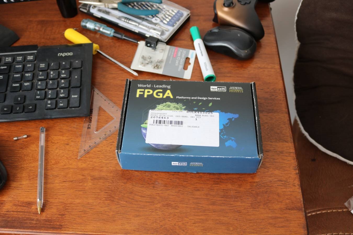
Recently I was selected to roadtest the terasIC DEO-NANO P0082 fpga development kit. My application was based around reviewing the P0082 for suitability as an entry level device to simplify the process of people wanting to explore fpga development for the first time.


As part of that roadtest application I offered to post regular blogs here in the fgpa group on element14 documenting my progress, this first post centered around the unboxing and first impressions.


image


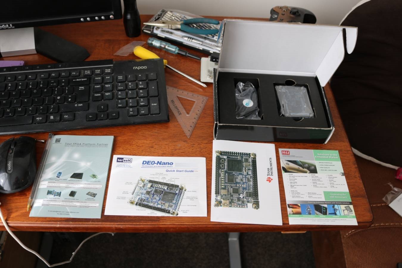
The Box Contains:

            - P0082 development board

            - Mini USB cable

            - Quick start guide

            - Brochures for other products


I always like getting brochures for other products!!


imageimage


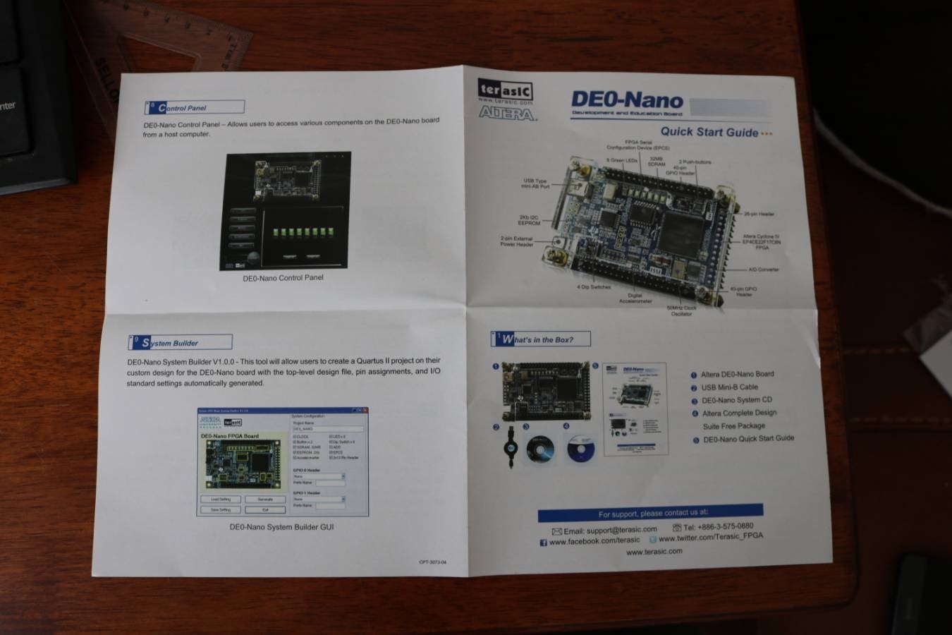
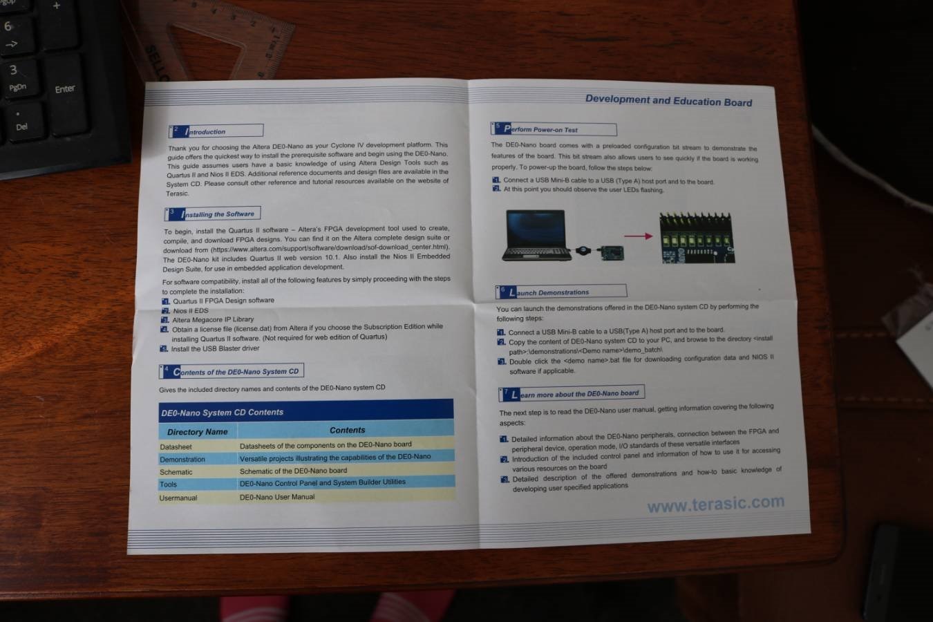
Quick start guide


Page 1 has a picture of the P0082 development board with labels to highlight the specific components.

Page 2 contains a brief introduction and a list of relevant software you will need to install to develope with the P0082.

Page 3 is an overview of the pre-loaded demonstration and links of where to download further demonstrations.

Page 4 looks at a control panel demonstration and a system builder tool to enable quick development on the P0082 (I'd imagine a project setup wizard).


imageimageimage


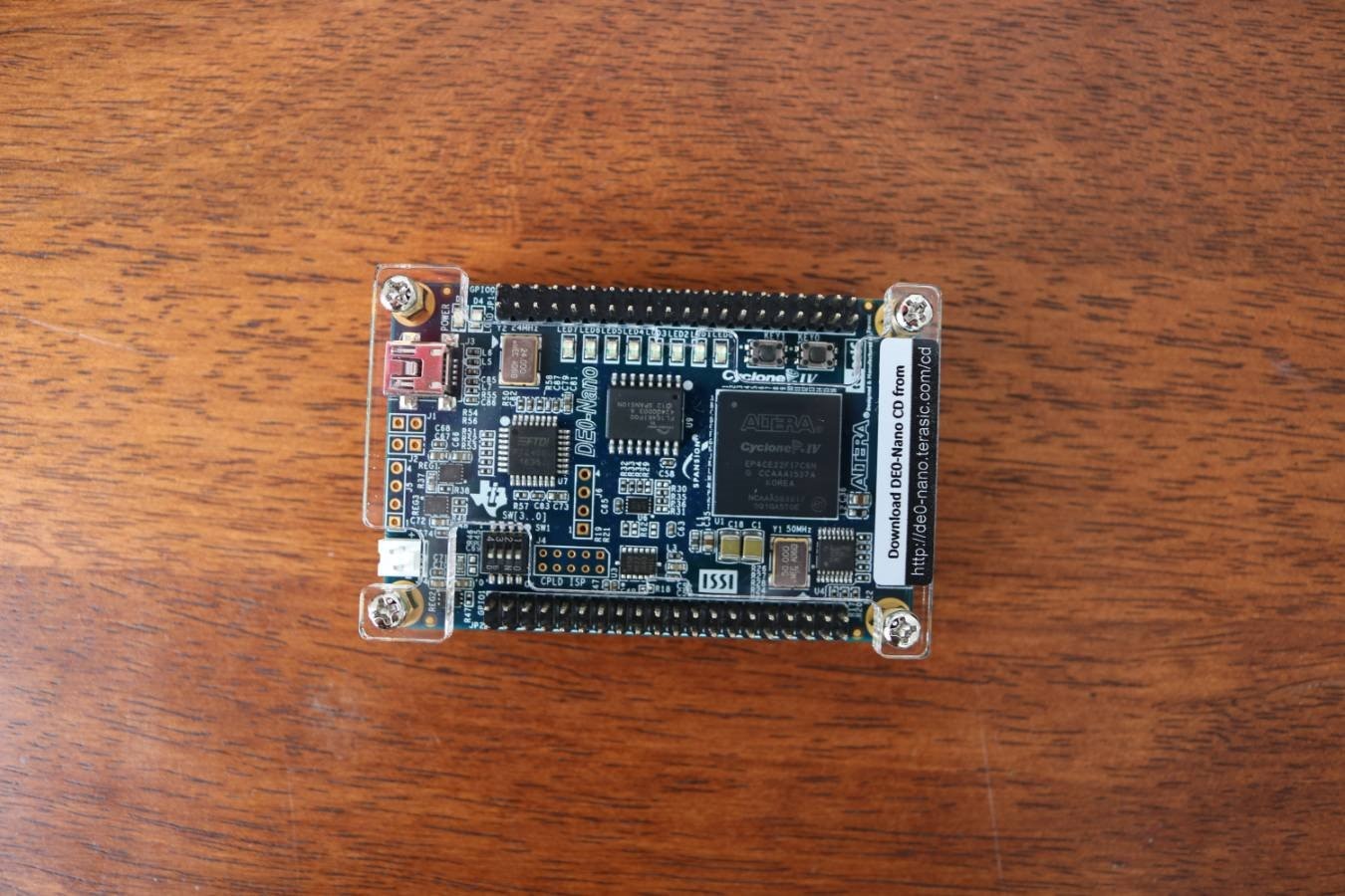
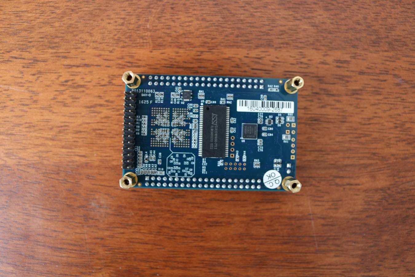
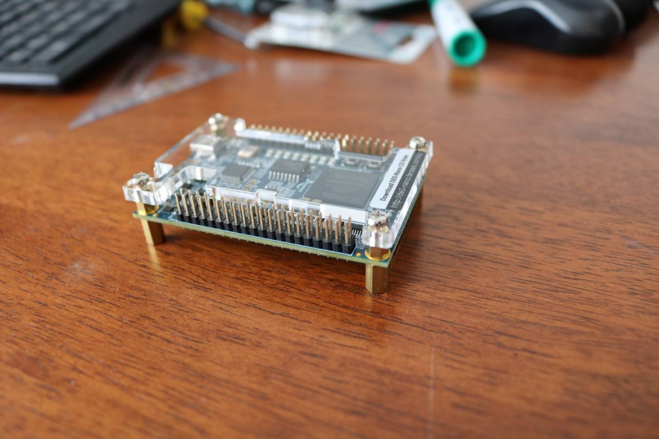
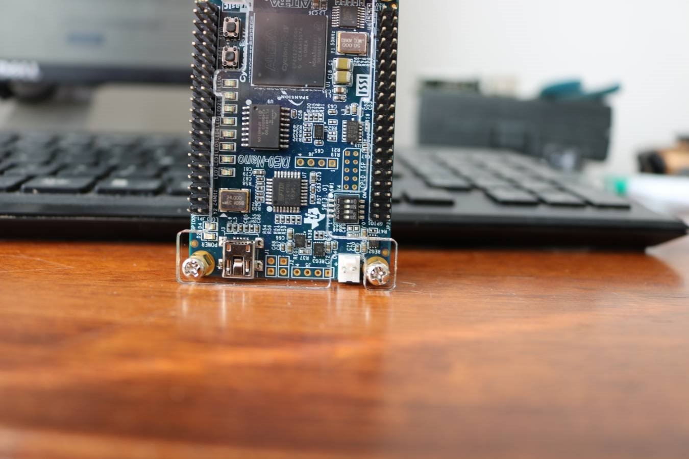
The P0082 development board looks well made, comes with a clear acrylic protective top cover and has standoffs to raise the bottom of the board from the surface its stood on which is a nice touch. The main component of the board is an Altera Cyclone 4. From what I understand at the moment, the Altera fpga loses all of it's configuration when power is removed and re-configures itself using an external EEPROM. To the left hand side of the board there is an I2C EEPROM so I'm assuming that this is where your compiled program (is that what you call it?) is downloaded from your computer onto ready for the fpga to read upon next power up.


Positive Comments


The development kit looks reasonably well presented, the quickstart guide is easy to follow and gives me confidence that the product is a worthy contender as an introductory device to the world of fpga's


Negative comments


One of the pins for the external power header is slightly bent, this coupled with the box looking rather worn and the software cd's that are supposed to be included are missing leads me to think this is a pre-used kit. Keep in mind though that this product was sent as a roadtest product and not one that has been purchased as new. Luckily the software packages can be downloaded easily enough so the missing cd's aren't a huge problem. Fingers crossed the board does function, I'll find out in due time!!

(edit) *after a quick power-up test, the P0082 is working fine and preloaded with the flashing led demo.


image


* Pictures taken with my new general purpose camera Canon EOS 750D

  • Sign in to reply

Top Comments

  • Former Member
    Former Member over 8 years ago in reply to michaelkellett +2
    Thanks! Yes I just found out this morning that the "image" was stored on an EPCS device when I was trying to find the driver to connect it to the computer and came across the technical docs for it!! The…
  • Former Member
    Former Member over 8 years ago in reply to jc2048 +2
    Thanks, theres some great advice there! Yes I have an oscilloscope to check things out with, one of the things I'll probably need advice with is how to get the image data into the fpga.
  • Former Member
    Former Member over 8 years ago in reply to msimon +2
    Hi Mehmet, Yes Ive used the programmer already, what Im talking about here is my eventual project where I intend to take some image data (from a picture) and use the fpga to display that onto an LED matrix…
Parents
  • michaelkellett
    michaelkellett over 8 years ago

    You haven't got it quite right re. the boot up process:


    Your board has  a small (2k) I2C EEPROM but this is far too tiny to store the boot up image for the FPGA - it has as an ECPS64 8Mbyte Flash chip for that. You are right that this FPGA (like many others) is RAM based so needs to copy the image from somewhere non volatile on power up. I don't know what to call the code like thing that FPGAs have so I call it an image so as not to mix it up with programmes for micros.


    I try not to talk about writing software for FPGAs  - after all VHDL and Verilog are both officially hardware description languages but it does sound a bit pompous to say I spent my morning describing hardware !


    Do you have a project in mind for the Nano ?


    MK

    • Cancel
    • Vote Up +1 Vote Down
    • Sign in to reply
    • More
    • Cancel
  • Former Member
    Former Member over 8 years ago in reply to michaelkellett

    Thanks! Yes I just found out this morning that the "image" was stored on an EPCS device when I was trying to find the driver to connect it to the computer and came across the technical docs for it!!


    The quick start guide says that the board comes pre-loaded with a bit stream to demonstrate the board but I'll probably stick to calling the result of the compiler an image like you, it sounds right.


    I'm gonna spend some time trying to get a basic working knowledge of the board first and then move onto using it to drive a 32x32 rgb led matrix as a first main project. Ive just tested out some of the demo's which install by running a batch file, I supposed its time to have a read of the full user manual and see if I can move forwards from there! image

    • Cancel
    • Vote Up +2 Vote Down
    • Sign in to reply
    • More
    • Cancel
  • jc2048
    jc2048 over 8 years ago in reply to Former Member

    I'd call it a 'bitstream' too (I've worked with Xilinx FPGAs in the past). 'Image' is ok in my book as well - it describes what is going on much better than the word program.


    Bit stream is good because it's a stream of bits being loaded into shift registers on the device. When all the bits are in the correct place, they get latched into place, taking over from the default settings and controlling the various elements of the FPGA (routing connections, etc).


    One thing that's useful to remember, if you're designing hardware to go around an FPGA, is that that process takes time [a considerable time, in electronic terms, if you're used to logic that just starts instantly] and until the bits get latched the FPGA will hold the I/O pins in a high impedance state. If you use the FPGA to generate chip selects to external devices, or that kind of thing, you may need to consider carefully what happens before the FPGA gets going to avoid conflicts [usually just a few carefully placed pull-ups or pull-downs will do].


    I can remember one design that I did that incorporated registers that an external processor could write to in order to set up various parameters. It didn't work when I tried it with a simple test program to load the registers, even though I could see on a 'scope the right data being written across. After spending a while looking at all the wrong things, in the way that you do sometimes, I thought to look at the signal that showed when the configuration was complete and realised that the processor was pushing the data across a couple of hundred milliseconds before the FPGA was finished with its configuration.


    An LED tile is a good project. LED displays lend themselves well to debugging designs - it makes for fast progress being able to see the mistakes in front of your face. Do you have an oscilloscope to look at waveforms?

    • Cancel
    • Vote Up +1 Vote Down
    • Sign in to reply
    • More
    • Cancel
  • Former Member
    Former Member over 8 years ago in reply to jc2048

    Thanks, theres some great advice there!


    Yes I have an oscilloscope to check things out with, one of the things I'll probably need advice with is how to get the image data into the fpga.

    • Cancel
    • Vote Up +2 Vote Down
    • Sign in to reply
    • More
    • Cancel
  • msimon
    msimon over 8 years ago in reply to Former Member

    There is a programmer inside the Quartus software. After compiling your code, you can upload image (SRAM Object File (.sof)) to FPGA via that tool.

    Mehmet

    • Cancel
    • Vote Up 0 Vote Down
    • Sign in to reply
    • More
    • Cancel
Comment
  • msimon
    msimon over 8 years ago in reply to Former Member

    There is a programmer inside the Quartus software. After compiling your code, you can upload image (SRAM Object File (.sof)) to FPGA via that tool.

    Mehmet

    • Cancel
    • Vote Up 0 Vote Down
    • Sign in to reply
    • More
    • Cancel
Children
  • Former Member
    Former Member over 8 years ago in reply to msimon

    Hi Mehmet,


    Yes Ive used the programmer already, what Im talking about here is my eventual project where I intend to take some image data (from a picture) and use the fpga to display that onto an LED matrix display. My question was how to get the image data from the picture into the fpga, Im sure there are plenty of ways that will become apparent but Im interested in other peoples ideas Relaxed

    • Cancel
    • Vote Up +2 Vote Down
    • Sign in to reply
    • More
    • Cancel
  • michaelkellett
    michaelkellett over 8 years ago in reply to Former Member

    I use mainly SPI or UART style interfaces to get control data in and out of FPGAs. For fast data transfer it's Gbit Ethernet or worse.


    If you are going from PC to FPGA it's easy to get up to about 1Mbit/s down an FTDI USB/uart lead and it appears to the PC like a com port. Then you can use the same port for debug and control, initially using a standard terminal programme on the PC. Later you can use VB, C, Python or whatever - and of course you can use any computer with a logic level UART interface.


    SPI is capable of going a good 20x faster but needs more work at the control end.


    UART or SPI are easy at the FPGA end.


    With only 1024 pixels you data rates won't be too demanding  - 50 frames per second would work on a 115200 baud UART connection.


    MK

    • Cancel
    • Vote Up +2 Vote Down
    • Sign in to reply
    • More
    • Cancel
  • msimon
    msimon over 8 years ago in reply to Former Member

    Ohh sorry

    I got it wrong. If you want to load an image like a picture, I think you can use I2C EEPROM. If you will show a frame, you can convert an image to a hex file and then upload to EEPROM. It is tiny but I think it may be enough to fit something for LED matrix.

    Mehmet

    • Cancel
    • Vote Up +1 Vote Down
    • Sign in to reply
    • More
    • Cancel
element14 Community

element14 is the first online community specifically for engineers. Connect with your peers and get expert answers to your questions.

  • Members
  • Learn
  • Technologies
  • Challenges & Projects
  • Products
  • Store
  • About Us
  • Feedback & Support
  • FAQs
  • Terms of Use
  • Privacy Policy
  • Legal and Copyright Notices
  • Sitemap
  • Cookies

An Avnet Company © 2025 Premier Farnell Limited. All Rights Reserved.

Premier Farnell Ltd, registered in England and Wales (no 00876412), registered office: Farnell House, Forge Lane, Leeds LS12 2NE.

ICP 备案号 10220084.

Follow element14

  • X
  • Facebook
  • linkedin
  • YouTube