element14 Community
element14 Community
    Register Log In
  • Site
  • Search
  • Log In Register
  • Community Hub
    Community Hub
    • What's New on element14
    • Feedback and Support
    • Benefits of Membership
    • Personal Blogs
    • Members Area
    • Achievement Levels
  • Learn
    Learn
    • Ask an Expert
    • eBooks
    • element14 presents
    • Learning Center
    • Tech Spotlight
    • STEM Academy
    • Webinars, Training and Events
    • Learning Groups
  • Technologies
    Technologies
    • 3D Printing
    • FPGA
    • Industrial Automation
    • Internet of Things
    • Power & Energy
    • Sensors
    • Technology Groups
  • Challenges & Projects
    Challenges & Projects
    • Design Challenges
    • element14 presents Projects
    • Project14
    • Arduino Projects
    • Raspberry Pi Projects
    • Project Groups
  • Products
    Products
    • Arduino
    • Avnet Boards Community
    • Dev Tools
    • Manufacturers
    • Multicomp Pro
    • Product Groups
    • Raspberry Pi
    • RoadTests & Reviews
  • Store
    Store
    • Visit Your Store
    • Choose another store...
      • Europe
      •  Austria (German)
      •  Belgium (Dutch, French)
      •  Bulgaria (Bulgarian)
      •  Czech Republic (Czech)
      •  Denmark (Danish)
      •  Estonia (Estonian)
      •  Finland (Finnish)
      •  France (French)
      •  Germany (German)
      •  Hungary (Hungarian)
      •  Ireland
      •  Israel
      •  Italy (Italian)
      •  Latvia (Latvian)
      •  
      •  Lithuania (Lithuanian)
      •  Netherlands (Dutch)
      •  Norway (Norwegian)
      •  Poland (Polish)
      •  Portugal (Portuguese)
      •  Romania (Romanian)
      •  Russia (Russian)
      •  Slovakia (Slovak)
      •  Slovenia (Slovenian)
      •  Spain (Spanish)
      •  Sweden (Swedish)
      •  Switzerland(German, French)
      •  Turkey (Turkish)
      •  United Kingdom
      • Asia Pacific
      •  Australia
      •  China
      •  Hong Kong
      •  India
      •  Korea (Korean)
      •  Malaysia
      •  New Zealand
      •  Philippines
      •  Singapore
      •  Taiwan
      •  Thailand (Thai)
      • Americas
      •  Brazil (Portuguese)
      •  Canada
      •  Mexico (Spanish)
      •  United States
      Can't find the country/region you're looking for? Visit our export site or find a local distributor.
  • Translate
  • Profile
  • Settings
FPGA
  • Technologies
  • More
FPGA
Blog Entering The World Of FPGA's with a DEO-NANO P0082 - Part 4 (moving on)
  • Blog
  • Forum
  • Documents
  • Quiz
  • Events
  • Polls
  • Files
  • Members
  • Mentions
  • Sub-Groups
  • Tags
  • More
  • Cancel
  • New
FPGA requires membership for participation - click to join
  • Share
  • More
  • Cancel
Group Actions
  • Group RSS
  • More
  • Cancel
Engagement
  • Author Author: Former Member
  • Date Created: 23 Aug 2017 2:04 PM Date Created
  • Views 1567 views
  • Likes 9 likes
  • Comments 9 comments
  • p0082
  • de0 nano
  • terasic
  • de0-nano
  • enterfpga
  • terasic p0082 de0-nano fpga development kit
Related
Recommended

Entering The World Of FPGA's with a DEO-NANO P0082 - Part 4 (moving on)

Former Member
Former Member
23 Aug 2017

So far the DE0-NANO P0082 development board and the associated user guides have given me a basic overview on how to develop with FPGA's and introduced me to a simple Verilog HDL file. To move forwards in FPGA development I would need to learn more about Verilog HDL and while Terasic have done a great job creating resources that teaches the basics of development I wouldn't expect them to provide me with a full Verilog HDL learning resource and so I looked elsewhere.


The first resource I found on Google was at http://www.asic-world.com/verilog/index.html and so I spent some time looking through their tutorials and examples, as with most new things I'm learning I find it useful to learn the basics and take a few days break. When I come back to the subject I find myself more able to understand what I'd learn previously and also learn more as I go.


After having a few days break, I decided to alter the files for the bitstream I made in Part 3 of this blog series. My intention was to create an 8-bit counter that displays on the LED's and the ability to change the direction of counting when one of the user buttons are pressed. Here is my new board layout :


image


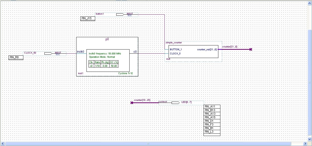
In the board layout you can see I kept the pll to provide the clock source, the simple_counter module now has an additional button input and Ive removed the multiplexer, choosing to output 8 bits from the counter bus straight to LED's.


Before we look at the Verilog file for the simple_counter component lets investigate that counter bus a little bit more in depth. The counter bus is a single trace here but its representing a 32 bit bus with 32 wires, so here we've connected wires 18,19,20,21,22,23,24 and 25 to LED's and left the others disconnected. Its possible to connect a consistent range of 8 wires from anywhere in this bus and the LED's will still show an 8 bit counter.


Whats really going on is that simple_counter actually outputs as a 32-bit counter on that bus and were selecting a range, if we select a range of 0,1,2,3,4,5,6 and 7 the counter will be running so fast as thats where the least significant bits are that we won't see the LED's change (they'll just appear constantly on) and if we select the range 24,25,26,27,28,29,30 and 31 the LED's will count too slowly this is because as we move up the range the speed of the bits changing becomes less frequent.


It's entirely possible to just get the simple_counter component to output an 8-bit bus rather than a 32-bit one and alter the pll to change its counting speed to one that would be more suitable but I just left this one in for well, who knows why I left it in, it was just there already I suppose!


Right lets look at the new Verlog HDL file:


image


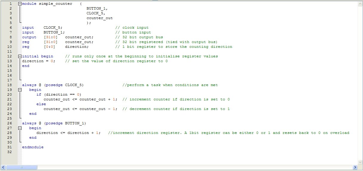
I added an extra button input and a new register component. Registers are similar to variables only you declare the size in bits you would like that register to be. So reg [31:0] is like a 32 bit variable and reg[0:0] is a single bit which Im using here like a Boolean to keep track of the direction.


You'll notice a new section titled "initial begin" this is a place you can initialise the values of the registers at the beginning of the bitstream launching/simulating.


Notice that there's 2 "always" blocks. These are functions that run automatically when their conditions are met. so the statements in the "always @ (posedge BUTTON_1)" block between "begin" and "end" will run automatically whenever a new positive edge is detected on the button (ie. whenever the button is pressed or goes high).


Multiple "always" statements are allowed in a component and can all run simultaneously.


and thats it for today, see the video below to see this in action image


You don't have permission to edit metadata of this video.
Edit media
x
image
Upload Preview
image

  • Sign in to reply

Top Comments

  • Former Member
    Former Member over 7 years ago in reply to johnbeetem +4
    It looks like Terasic have really gone to town on the button debouncing here! So underneath each button is the usual 2 resistor, 1 capacitor debounce circuit but I noticed in the user guide it mentions…
  • DAB
    DAB over 7 years ago +3
    Very good project Lucie. You are definitely answer my questions about how easy it is for a newbie to pick up and use this device. Well done. DAB
  • rachaelp
    rachaelp over 7 years ago +3
    Nice work Lucie, you're making really good progress with learning about FPGA's. I can't wait to see you're next blog in this series! Rachael
Parents
  • johnbeetem
    johnbeetem over 7 years ago

    Very nice!  In the video the the button seems to work reliably, switching direction with each press.  Did you see that in practice?  Usually when you push or release a mechanical button you get "contact bounce" where the contacts open an close multiple times over a few milliseconds.  If you get the wrong odd/even number of bounces, "direction" will toggle back to its previous value.  One solution for this is to sample the switch multiple times over a 10 msec interval (or so) and do a majority filter of the result.

    • Cancel
    • Vote Up +1 Vote Down
    • Sign in to reply
    • More
    • Cancel
  • Former Member
    Former Member over 7 years ago in reply to johnbeetem

    It looks like Terasic have really gone to town on the button debouncing here! So underneath each button is the usual 2 resistor, 1 capacitor debounce circuit but I noticed in the user guide it mentions them being debounced through a schmitt trigger and sure enough, just off to the side is a Texas Instrument MS17 schmitt trigger buffer (with 6 independent channels). There are 4 dip switches on the board too so presumably this schmitt trigger is also debouncing those too.


    So yeah... Resistor capacitor debouncing coupled with schmitt trigger debouncing, theyre not leaving any room for error.

    • Cancel
    • Vote Up +4 Vote Down
    • Sign in to reply
    • More
    • Cancel
  • johnbeetem
    johnbeetem over 7 years ago in reply to Former Member

    lucie tozer wrote:


    So yeah... Resistor capacitor debouncing coupled with schmitt trigger debouncing, theyre not leaving any room for error.

    Nice.  They're obviously trying to avoid subtle problems to minimize sources of frustration.  One challenge for getting people to use FPGAs is that once they start wiring things up they get exposed to all sorts of lovely physics effects so if they're from a software-only background the learning curve gets even steeper than it already is.

    • Cancel
    • Vote Up +2 Vote Down
    • Sign in to reply
    • More
    • Cancel
Comment
  • johnbeetem
    johnbeetem over 7 years ago in reply to Former Member

    lucie tozer wrote:


    So yeah... Resistor capacitor debouncing coupled with schmitt trigger debouncing, theyre not leaving any room for error.

    Nice.  They're obviously trying to avoid subtle problems to minimize sources of frustration.  One challenge for getting people to use FPGAs is that once they start wiring things up they get exposed to all sorts of lovely physics effects so if they're from a software-only background the learning curve gets even steeper than it already is.

    • Cancel
    • Vote Up +2 Vote Down
    • Sign in to reply
    • More
    • Cancel
Children
No Data
element14 Community

element14 is the first online community specifically for engineers. Connect with your peers and get expert answers to your questions.

  • Members
  • Learn
  • Technologies
  • Challenges & Projects
  • Products
  • Store
  • About Us
  • Feedback & Support
  • FAQs
  • Terms of Use
  • Privacy Policy
  • Legal and Copyright Notices
  • Sitemap
  • Cookies

An Avnet Company © 2025 Premier Farnell Limited. All Rights Reserved.

Premier Farnell Ltd, registered in England and Wales (no 00876412), registered office: Farnell House, Forge Lane, Leeds LS12 2NE.

ICP 备案号 10220084.

Follow element14

  • X
  • Facebook
  • linkedin
  • YouTube