element14 Community
element14 Community
    Register Log In
  • Site
  • Search
  • Log In Register
  • Community Hub
    Community Hub
    • What's New on element14
    • Feedback and Support
    • Benefits of Membership
    • Personal Blogs
    • Members Area
    • Achievement Levels
  • Learn
    Learn
    • Ask an Expert
    • eBooks
    • element14 presents
    • Learning Center
    • Tech Spotlight
    • STEM Academy
    • Webinars, Training and Events
    • Learning Groups
  • Technologies
    Technologies
    • 3D Printing
    • FPGA
    • Industrial Automation
    • Internet of Things
    • Power & Energy
    • Sensors
    • Technology Groups
  • Challenges & Projects
    Challenges & Projects
    • Design Challenges
    • element14 presents Projects
    • Project14
    • Arduino Projects
    • Raspberry Pi Projects
    • Project Groups
  • Products
    Products
    • Arduino
    • Avnet Boards Community
    • Dev Tools
    • Manufacturers
    • Multicomp Pro
    • Product Groups
    • Raspberry Pi
    • RoadTests & Reviews
  • Store
    Store
    • Visit Your Store
    • Choose another store...
      • Europe
      •  Austria (German)
      •  Belgium (Dutch, French)
      •  Bulgaria (Bulgarian)
      •  Czech Republic (Czech)
      •  Denmark (Danish)
      •  Estonia (Estonian)
      •  Finland (Finnish)
      •  France (French)
      •  Germany (German)
      •  Hungary (Hungarian)
      •  Ireland
      •  Israel
      •  Italy (Italian)
      •  Latvia (Latvian)
      •  
      •  Lithuania (Lithuanian)
      •  Netherlands (Dutch)
      •  Norway (Norwegian)
      •  Poland (Polish)
      •  Portugal (Portuguese)
      •  Romania (Romanian)
      •  Russia (Russian)
      •  Slovakia (Slovak)
      •  Slovenia (Slovenian)
      •  Spain (Spanish)
      •  Sweden (Swedish)
      •  Switzerland(German, French)
      •  Turkey (Turkish)
      •  United Kingdom
      • Asia Pacific
      •  Australia
      •  China
      •  Hong Kong
      •  India
      •  Korea (Korean)
      •  Malaysia
      •  New Zealand
      •  Philippines
      •  Singapore
      •  Taiwan
      •  Thailand (Thai)
      • Americas
      •  Brazil (Portuguese)
      •  Canada
      •  Mexico (Spanish)
      •  United States
      Can't find the country/region you're looking for? Visit our export site or find a local distributor.
  • Translate
  • Profile
  • Settings
FPGA
  • Technologies
  • More
FPGA
Blog Entering The World Of FPGA's with a DEO-NANO P0082 - Part 5 (modelling a M74HC590)
  • Blog
  • Forum
  • Documents
  • Quiz
  • Events
  • Polls
  • Files
  • Members
  • Mentions
  • Sub-Groups
  • Tags
  • More
  • Cancel
  • New
Join FPGA to participate - click to join for free!
  • Share
  • More
  • Cancel
Group Actions
  • Group RSS
  • More
  • Cancel
Engagement
  • Author Author: Former Member
  • Date Created: 24 Aug 2017 7:17 PM Date Created
  • Views 3799 views
  • Likes 6 likes
  • Comments 28 comments
  • p0082
  • terasic
  • deo-nano p0082
  • de0-nano
  • enterfpga
  • p0082(terasic)
  • terasic p0082 de0-nano fpga development kit
Related
Recommended

Entering The World Of FPGA's with a DEO-NANO P0082 - Part 5 (modelling a M74HC590)

Former Member
Former Member
24 Aug 2017

Ive been recently using an M74HC590 binary counter to capture some data from an opto-encoder and thought that since I'd modelled a basic binary counter into the FPGA, why don't I go the whole hog and model this real world component into it too and make a final blog post in this series.


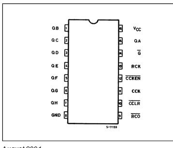
Here's the front page and the pinout  in the datasheet for the M74HC590 that I'll be modelling:

image

image


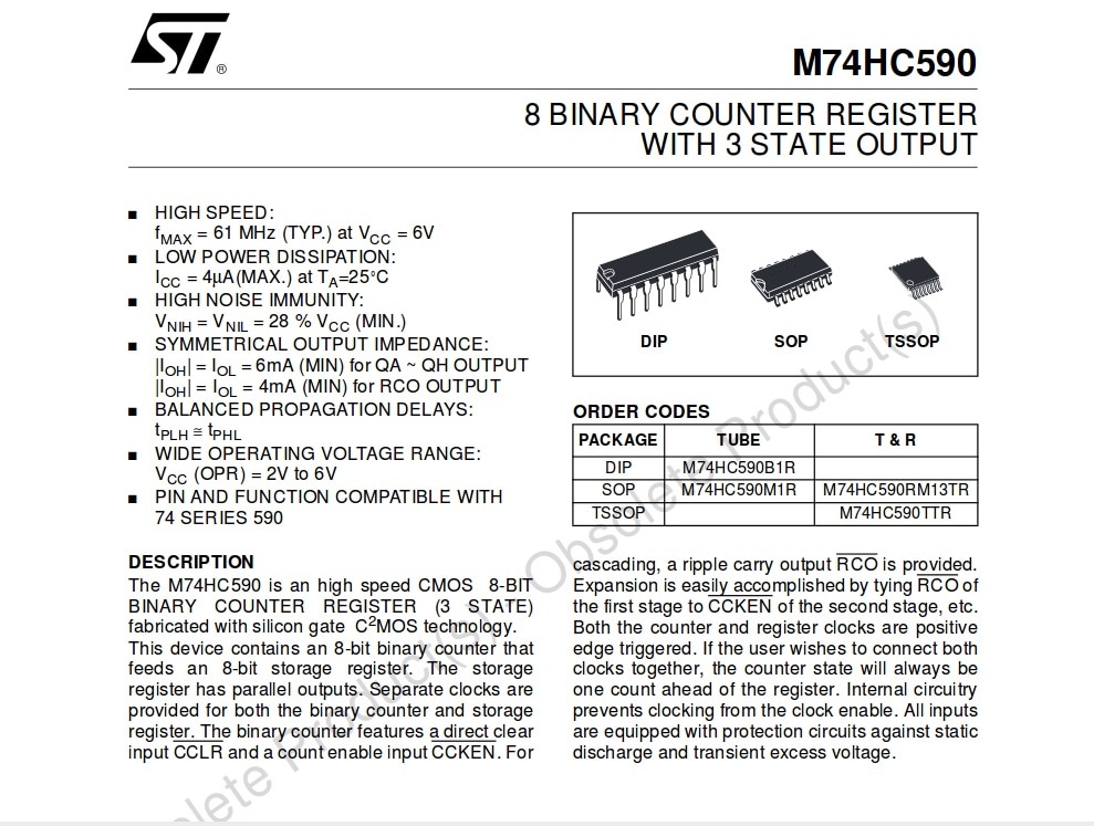
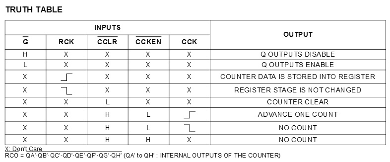
So we know what the inputs and outputs are of the device are but what about the way it functions internally? Well I looked through the datasheet and found a truth table that I could work things out from.


image


Using this data, I made up the following Verilog file:


image


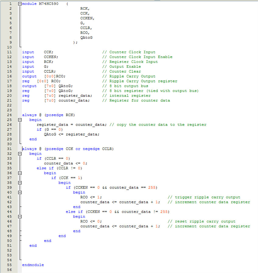
As you can see Ive copied the pin labels etc.. and used nested if's to do most of the logic.


image


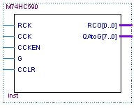
Once were happy with the Verilog file, we generate the board symbol shown here. Theres the corresponding input pins and the output pins QA throught to QG are shown as a single wire representing the 8bit output bus.


In the following schematic, Ive added the symbol for the Verilog file and made some connections to it:


image


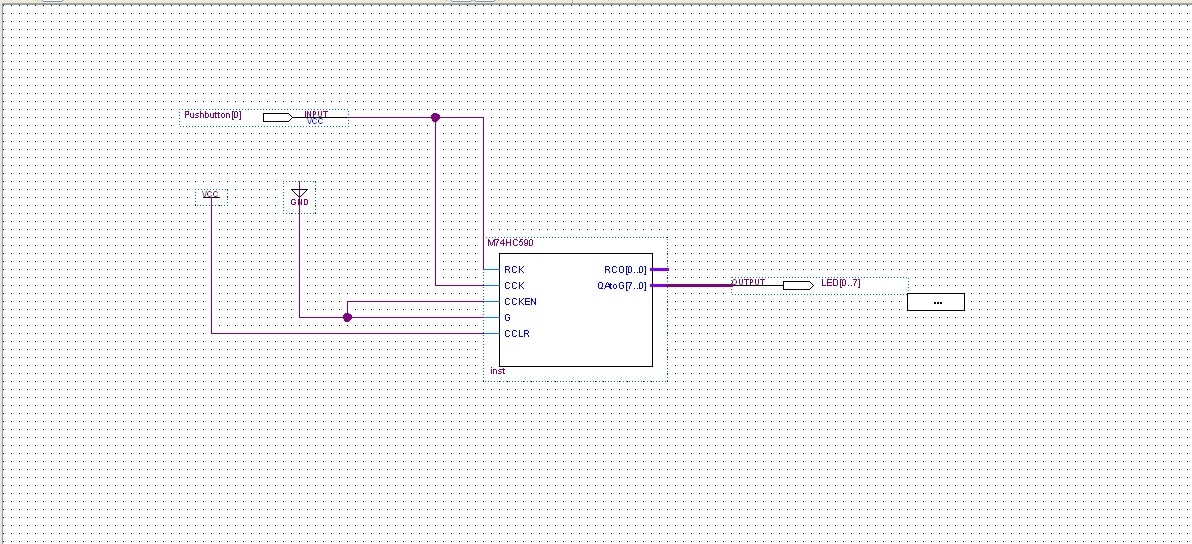
The CCKEN and G pins have been connected to an internal Ground and CCLR has been connecting to an internal voltage source (VCC). These could have been broken out to real pins on the DE0-NANO P0082 board and connected manually but I did it this way for simplicity.


The RCK and CCK pins have both been connected to a push button on the development board.


The QA - QG outputs have all been connected to the LED's on the development board and the RCO pin has been left unconnected for the time being. This output would be connected to another 8-bit counter if they were being cascaded into a 16-bit counter.


From here it was just a case of assigning the LED's and pushbutton to the correct pins and the device is ready to test. The video at the bottom of this shows the final programmed development board. Because the CCK and RCK pins were attached to a push button, simply pressing that button causes the device to count up press by press.


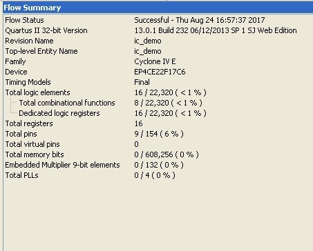
Heres the compiler summary for the above component, very few of the actual resources were used (in most cases less than 1%):


image


Hopefully this gives an insight into how fpga's can be utilised by modelling existing components that we already know, this is the final blog post in this mini-series but I will be posting occasional updates of my progress on an rgb led matrix driver that Im working towards with the DE0-NANO. I intend to cheat a little bit to start with and initialise some registers with a test pattern while I work out how to drive the signal properly. Once that's done I can work backwards into a more complex design.
image


You don't have permission to edit metadata of this video.
Edit media
x
image
Upload Preview
image

  • Sign in to reply

Top Comments

  • Former Member
    Former Member over 7 years ago in reply to rachaelp +5
    Yes Im planning on doing another post or 2 when I get underway with the led matrix display driver and then who knows maybe some other project in the future too. Hopefully others will stumble across this…
  • Former Member
    Former Member over 7 years ago in reply to michaelkellett +3
    Thanks for explaining! It does appear to function as expected so I'm going to call it a partial win, although I'm plenty sure that your explanation for why it's not the best way to go about it will become…
  • michaelkellett
    michaelkellett over 7 years ago in reply to Former Member +3
    Good luck - it's good for me to be forced to think about Verilog. I'll try to repeat your code in VHDL in the next few days and post it here so you can see the difference. MK
  • johnbeetem
    johnbeetem over 7 years ago in reply to michaelkellett

    Michael Kellett wrote:


    Its not a surprise that X's tools are nicer - they probably spent more than Lattice's annual turnover on developing Vivado.

    I notice Lattice grew 16% from 2015 to 2016, beating the others' growth rates by a lot.  2015 was the year the open-source IceStorm tools were first released.  Post hoc ergo propter hoc! image


    I can't compare IceStorm to Lattice's own tools, since I've never used the latter, but I find IceStorm very nice -- especially when used with XXICC image   Lattice didn't have to spend anything on those tools.

    • Cancel
    • Vote Up +2 Vote Down
    • Sign in to reply
    • More
    • Cancel
  • michaelkellett
    michaelkellett over 7 years ago in reply to rachaelp

    I thought that Lattice were number three but you are quite right in picking Microsemi.


    This is from EET:

    Guesstimate of final numbers x 1,000,000 (Source: Paul Dillien)

    Its not a surprise that X's tools are nicer - they probably spent more than Lattice's annual turnover on developing Vivado.


    They are all very small compared with total semiconductor manufacture.


    MK

    • Cancel
    • Vote Up +3 Vote Down
    • Sign in to reply
    • More
    • Cancel
  • Former Member
    Former Member over 7 years ago in reply to rachaelp

    Yes Im planning on doing another post or 2 when I get underway with the led matrix display driver and then who knows maybe some other project in the future too.


    Hopefully others will stumble across this blog series and realise it's not out of reach to start developing on FPGA's. Of course there's more to learn as more complex designs are used but to get a basic understanding of how to develop is pretty much straight forwards now!

    • Cancel
    • Vote Up +5 Vote Down
    • Sign in to reply
    • More
    • Cancel
  • rachaelp
    rachaelp over 7 years ago in reply to michaelkellett

    Michael Kellett wrote:


    Actually, TBP (To Be Pedantic) Lattice bundle a cut down version of Aldec HDL - I think it's much nicer to use than Modelsim. Xilinx Vivado has X's own simulator - it's quite usable too, and I think faster than the Lattice version of Aldec.


    On a tight budget and just starting I would recommend Lattice - hand solderable (well hotplate anyway) 48 pin parts with 4k LUTs and soon with a big embedded memory and about £5 for a chip as well as free tools and cheap dev boards (and open source tools as well if that's important to you).


    MK

    All good points. I've not looked at Vivado, as I said I have been out of the FPGA game for a while so am a little rusty. ModelSim was bundled with Altera, Xilinx and Actel (Microsemi) last time I looked. Also, TBP, I did say all the MAIN vendors, I consider Lattice to be a bit of a niche vendor on the fringe of FPGA's image

    • Cancel
    • Vote Up +3 Vote Down
    • Sign in to reply
    • More
    • Cancel
  • rachaelp
    rachaelp over 7 years ago in reply to johnbeetem

    John Beetem wrote:


    Thanks to Lucie's 'blogs, I think we've had more FPGA activity in the last month than in the previous two years. Kudos!

    Yes definitely!


    Lucie, you mentioned that this is the last one you planned in the series, but I really hope you'll consider writing more blogs on this subject as you continue to explore and learn about FPGA's image

    • Cancel
    • Vote Up +2 Vote Down
    • Sign in to reply
    • More
    • Cancel
>
element14 Community

element14 is the first online community specifically for engineers. Connect with your peers and get expert answers to your questions.

  • Members
  • Learn
  • Technologies
  • Challenges & Projects
  • Products
  • Store
  • About Us
  • Feedback & Support
  • FAQs
  • Terms of Use
  • Privacy Policy
  • Legal and Copyright Notices
  • Sitemap
  • Cookies

An Avnet Company © 2025 Premier Farnell Limited. All Rights Reserved.

Premier Farnell Ltd, registered in England and Wales (no 00876412), registered office: Farnell House, Forge Lane, Leeds LS12 2NE.

ICP 备案号 10220084.

Follow element14

  • X
  • Facebook
  • linkedin
  • YouTube