


The enhanced Pulse Width Modulation (ePWM) IP creation has only one objective, to reduce the processor time required for direction control in the motor driver. It is based on a 32-bit signed int data type and can handle positive and negative values. A positive number indicates a clockwise rotation action while a negative number allows a counterclockwise rotation.
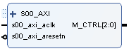
ePWM IP
The motor control port (M_CTRL) has 3 signals: Enable, PWM, and Direction. At this moment, the Enable signal is always assigned to 1, to maintain the motor activated according to the motor driver architecture. PWM handles a duty cycle from 0 to (Width - 1), this allows a complete deactivation of the channel. Finally, Direction changes the rotation direction.
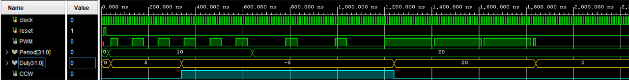
ePWM simulation
`timescale 1ns / 1ps

module PWM(
    input clock,
    input reset,
    input [31:0] Width,
    input signed [31:0] Duty,
    output reg oPWM,
    output oDIR
    );

reg [31:0] count;
wire [31:0] aDuty;

assign aDuty = Duty[31]? -Duty[31:0]: Duty[31:0];

always @ (posedge clock)
begin
    if(reset) begin
        count = 0;
    end else begin
        if(!(count < Width)) begin
            count = 0;
        end else begin
            count = count + 1;
        end
    end
end

always @ count
begin
    if(count < aDuty) begin
        oPWM = 1;
    end else begin
        oPWM = 0;
    end
end

assign oDIR = Duty[31];

endmodule
All the processing required by software for the direction change using a GPIO is delegated to the ePWM with a direct connection to the control terminals. The module only requires two values: the Period and the Duty cycle. This approach allows replacing the following code,
...

static uint32_t pPWM;

response = PID_CalcResponse(&MotorCtrl, (float)sMt -> Position);

if(response >= 0)
	OUTS -> DATA2 |= 0x02;
else
	OUTS -> DATA2 &= 0x0D;

pPWM = (uint32_t)(fabs(response));

*Duty = (uint32_t)pPWM;

...
For the next one,
...

response = PID_CalcResponse(&MotorCtrl, (float)sMt -> Position);

*Duty = (int32_t)response;

...
It is required only a typecasting to accomplish the module design and all additional validations are made by hardware, obtaining the same results with less processor time.