


Last month I looked at three different FPGA dev kits. You will have seen that I have selected the XuLA FPGA board from XESS that uses a Xilinx chip at its core. This month I want to go though the initial design process I use when designing a FPGA project. Then over the following posts you will see my progress, see the code I write and hopefully start to understand FPGA’s and my chosen language of VHDL.
Outline: So I want to know what the temperature is? I want to display this on a different type of display than normal, something a little fun looking. I’m only interested in seeing the temperature in ‘C and pulse or minus one on the display is fine.
The Hardware: So as I have said I’m using the XuLA FPGA board. As a display I have decided to use the LED 5x8 Matrix that's available from Tautic.com. I’m also going to use one of the pnp driver boards from Tautic also to help with the line driving of the LED’s. I also found while I was on the site a great and low cost temperature sensor. Its the MAX31855 K-type thermocouple that I can plug straight into a bread board. So no soldering required for this project then!
The circuit for the external hardware is as follows - in its basic form:
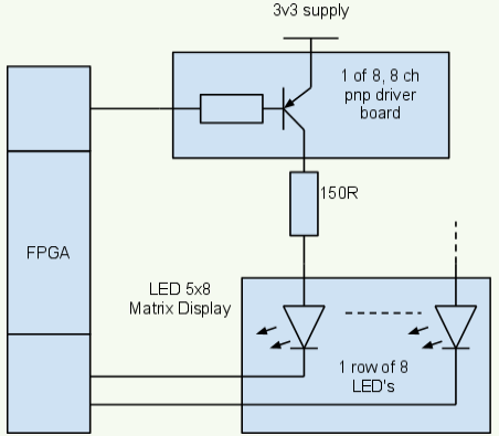
Above you can see that I will use 8 lines from the FPGA to drive the pnp driver board. This then allows me to switch current to a row of 5 LEDs. The other side of the LEDs can then be pulled low to 0 volts by 5 other outputs from the FPGA. You should note here that to turn on the pnp transistor I need to send it a zero (low) and also a zero (low) to one of the five pins that pull the LEDs to 0 volts to get the LED to light. So we need a 0 and a 0 to turn on a LED.
Because the LED matrix is 5 by 8 I’m going to use it on its side. That way I can get two digits on it that are 4 by 5 in size. Its actually 3 by 5 as I need a space between them.
As for the Thermocouple, I’ll come back to that in a later post. This is because I want the split the project up into two parts. So first I’ll work on getting the display working, then feeding it with temperature data.
So now you can see the external display hardware lets look at what we need to drive this internally with logic from a block point of view. I’m going to start were the XuLA demo leaves off which is with a clock input driving a counter (23 bit) and blinks a LED. This I’ll use as my data input for now and as a clock divider while I play around with the display update rates (will fix this up later).
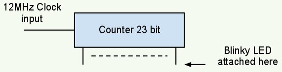
The Blinky LED flashes at bit more than once per second so is running at a good speed for us to test with. So the first thing I’ll do is to add 7 bits to this counter and use these top 8 bits as my data input to the display (bits 22 to 29).
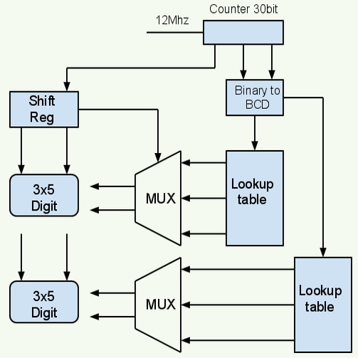
Now that I have 8 bit data I need to consider how I will turn this into data to display. I could get a number as large as “255” from the 8 bits but as I’m only using two digits on the display I actually only care about “00” to “99”. If you have written software you may know about BDC (binary-coded decimal). This allows you to code a number into 4 bit blocks. So one 8 bit byte can store between 00 and 99, just want we want. If we wanted the full reading of “255” then we would need a extra 4 bits making it a 12 bit byte.
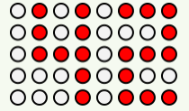
After breaking our data down so that we have each 4 bits holding a digit or value from 0 to 9 we then need to display them. Looking back at the LED graphic above you can see that to display the number “42” you just need a sequence of 1’s and 0’s. Noting that we need 0’s to turn a LED on, then the digit “2” would be coded as (from top to bottom as);
1000
1110
1000
1011
1000
So what we will need is a lookup table that will convert our signal digit from one of the 4 bits into a bit patten as show above.
As suggested already we need to drive each line one at a time. So the FPGA will power one row at a time and then drive the right patten for the row, from the bit patten above. Don’t worry, it will all make sense!
So having a look-up table generating our bit patten is one thing. As I have said we now need to drive each row in turn. This we can do with a simple shift register holding the value “11110”. One bit for each row, the zero pulling that row of LEDs to 0 volts. This patten or output from the shift register can be driven directly to the LEDs. The speed at which the shift register rotates will be our scan rate. As I said at first I’ll use a output from the counter as its quick and dirty way of changing the speed and testing - in my view anyway.
The last thing we need is a block that takes in the bit patten and then drives out the line of data biased on the value, or state of the shift register. So this means the shift register not only drives the LEDs 0 volt line but selects or gates out the right patten at the right time. Below is the block drawing for this.
So having got our top level design we will design each block in turn. And that will be the subject of the next blog where I will look at the code for each block.
Thanks
Paul (@monpjc)
