element14 Community
element14 Community
    Register Log In
  • Site
  • Search
  • Log In Register
  • Community Hub
    Community Hub
    • What's New on element14
    • Feedback and Support
    • Benefits of Membership
    • Personal Blogs
    • Members Area
    • Achievement Levels
  • Learn
    Learn
    • Ask an Expert
    • eBooks
    • element14 presents
    • Learning Center
    • Tech Spotlight
    • STEM Academy
    • Webinars, Training and Events
    • Learning Groups
  • Technologies
    Technologies
    • 3D Printing
    • FPGA
    • Industrial Automation
    • Internet of Things
    • Power & Energy
    • Sensors
    • Technology Groups
  • Challenges & Projects
    Challenges & Projects
    • Design Challenges
    • element14 presents Projects
    • Project14
    • Arduino Projects
    • Raspberry Pi Projects
    • Project Groups
  • Products
    Products
    • Arduino
    • Avnet Boards Community
    • Dev Tools
    • Manufacturers
    • Multicomp Pro
    • Product Groups
    • Raspberry Pi
    • RoadTests & Reviews
  • Store
    Store
    • Visit Your Store
    • Choose another store...
      • Europe
      •  Austria (German)
      •  Belgium (Dutch, French)
      •  Bulgaria (Bulgarian)
      •  Czech Republic (Czech)
      •  Denmark (Danish)
      •  Estonia (Estonian)
      •  Finland (Finnish)
      •  France (French)
      •  Germany (German)
      •  Hungary (Hungarian)
      •  Ireland
      •  Israel
      •  Italy (Italian)
      •  Latvia (Latvian)
      •  
      •  Lithuania (Lithuanian)
      •  Netherlands (Dutch)
      •  Norway (Norwegian)
      •  Poland (Polish)
      •  Portugal (Portuguese)
      •  Romania (Romanian)
      •  Russia (Russian)
      •  Slovakia (Slovak)
      •  Slovenia (Slovenian)
      •  Spain (Spanish)
      •  Sweden (Swedish)
      •  Switzerland(German, French)
      •  Turkey (Turkish)
      •  United Kingdom
      • Asia Pacific
      •  Australia
      •  China
      •  Hong Kong
      •  India
      •  Korea (Korean)
      •  Malaysia
      •  New Zealand
      •  Philippines
      •  Singapore
      •  Taiwan
      •  Thailand (Thai)
      • Americas
      •  Brazil (Portuguese)
      •  Canada
      •  Mexico (Spanish)
      •  United States
      Can't find the country/region you're looking for? Visit our export site or find a local distributor.
  • Translate
  • Profile
  • Settings
FPGA
  • Technologies
  • More
FPGA
Blog FPGA Design Guide Pt3
  • Blog
  • Forum
  • Documents
  • Quiz
  • Events
  • Polls
  • Files
  • Members
  • Mentions
  • Sub-Groups
  • Tags
  • More
  • Cancel
  • New
Join FPGA to participate - click to join for free!
  • Share
  • More
  • Cancel
Group Actions
  • Group RSS
  • More
  • Cancel
Engagement
  • Author Author: pjclarke
  • Date Created: 11 Mar 2012 6:45 PM Date Created
  • Views 1539 views
  • Likes 1 like
  • Comments 5 comments
  • xilinx
  • fpga
  • xula
  • vhdl
Related
Recommended

FPGA Design Guide Pt3

pjclarke
pjclarke
11 Mar 2012

So over the last few months if you have been following my FPGA Design guide you will see that I have first blocked out the chucks of logic I needed, then last time I showed you the code used to get my first part of the temperature display working. However I said last time that having all the code in one block of VHDL makes it hard to read and is not a good idea. So this time lets look at the structure of VHDL and using separate files, ‘components’ and get our heads round the ‘entity’ and ‘architecture’ of VHDL.

So starting with the ‘entity’ statement as this is our top level for any design or sub unit. Its easy to forget when writing VHDL that its hardware, so lets think about this as if we were wiring up real chips on a bread board. The ‘entity’ therefore for the purpose of this example is going to be your chips pin out.

entity counter_30bit is
    Port ( clk_i : in  STD_LOGIC;
           count : out  STD_LOGIC_VECTOR (29 downto 0));
end counter_30bit;

Above is the entity for just our counter.


image

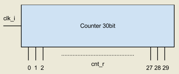
As you can see the entity lists the names of the pins and if its a input or output. All or pins and signals so far have been listed as STD_LOGIC, this is a single wire that can be logic level ‘1’ or ‘0’. When you see a reference to STD_LOGIC_VECTOR then we are talking about a number of wires like a data bus. The statement that follows explains the width and designations of the wires. Here you can see we have 30 wires labeled bit 0 to 29. The reason for the downto keyword explains that its bit 29 that is the MSB.

So next is the architecture and again we look at our counter as a separate unit.

architecture Behavioral of counter_30bit is
signal cnt_r : std_logic_vector(29 downto 0) := (others=>'0');
begin
process(clk_i) is
begin
  if rising_edge(clk_i) then
   cnt_r <= cnt_r + 1;
  end if;
end process;
count <= cnt_r;
end Behavioral;

This section as we have said before is the functanl bit of the VHDL. If this was a chip then its the bit that explains how the device works. Anything in here is completely separate from the outside world and hardware that connects to the block via the port entity can only see the connected signals.

So the next question is how do you connect this counter or ‘chip’ to others to make up your full circuit. Well this we can do via the ‘component’ keyword. From a chip and hardware point of view we would need a Bill of Materials (BOM) and also a Net list so we know what to connect where. In VHDL we will do the same sort of thing.

So if we want to use our counter in our design we first must tell VHDL what it is. This component deceleration is just like our BOM list.

component counter_30bit
port (
   clk_i : in STD_LOGIC;
   count : out STD_LOGIC_VECTOR (29 downto 0)
);
end component;

This looks a lot like the entity and that's because we are just listing the interface. This delectation will appear inside the architecture of the VHDL code before the ‘begin’ statement. After the begin statement in the functionally bit we need to create our Net list connections to other logic.

counter : component counter_30bit
          port map ( clk_i => clk_i,
                          count => cnt_r );

Here we list the component we want to use and then use the ‘port map’ keyword to generate the Net connections. I always think of this as ‘map-ing’ the pins of the chip to the signals. Here we list inside the port map first the pin (clk_i and count are the names used in the component) that then map to the signals in my design ( clk_i and cnt_r are local signals).

Improving on the original design and VHDL below I have attached all the new files. Here I have broken out each sub block and made it into a component. My top level design then only has to connect up the components, bit like wiring up chips on  a bread board.

The advantage of all this is that the blocks are easier to understand and also can be tested alone. Also means that you can use them as many times as you like in a design or in other designs.

Attachments:
e14_display_001.zip
  • Sign in to reply
  • michaelkellett
    michaelkellett over 13 years ago in reply to pjclarke

    I've always thought that it was generally a good idea to follow conventions and standards.


    And I think that is the main argument for using numeric - it is the IEEE standard. The problem with both being used is that it makes for code portability and readability issues - eg. my surprise at you adding an integer to a std_logic_vector.


    I like reading code written by 'sheep' because it's much easier to understand !


    Michael Kellett

    • Cancel
    • Vote Up 0 Vote Down
    • Sign in to reply
    • More
    • Cancel
  • pjclarke
    pjclarke over 13 years ago in reply to michaelkellett

    Hi Miehael,


    You make a valid point in that there is lots of people screaming that 'numeric_std' should be used and I fully understand why this is and the differences between the two libraries down to their functional methods that are used within them.


    The use of the libraries I have used in this instant really make no difference as they both work equally well for what I'm doing and the outcome is no difference on the Xilinx ISE. Where is will make a difference I will use the library I feel is the best fit for what I want. You will also see from Pt1 of this series that this code is actually carried over from an other engineers example. I have maintained therefore these methods so that people can move the original example that I did not write to mine. I'm not excusing myself - simply explaining.


    I am for reference against people blindly following numeric_std without understanding it - and is not relevant to this thread however people can read my view on the link below. Engineers are required to make an informed decision.


    http://engineerblogs.org/2011/04/vhdl-numeric-library-sheep/

    • Cancel
    • Vote Up 0 Vote Down
    • Sign in to reply
    • More
    • Cancel
  • michaelkellett
    michaelkellett over 13 years ago in reply to pjclarke

    Now I'm more suprised,


    the use of IEEE.STD_LOGIC_UNSIGNED.ALL is so generally out of favour that I am unfamiliar with its contents.


    In any tutorial material I would expect:


    library ieee;

    use ieee.std_logic_1164.all;

    use ieee.numeric_std.all;


    It is a good idea to refer to the included libraries in the example rather than just in an attachment.


    You may not be aware of the reasons that std_logic_unsigned should be avoided - there are many references on the web - I've quoted one below:


    from


    http://tams-www.informatik.uni-hamburg.de/vhdl/doc/faq/FAQ1.html#4.11


    4.11 Arithmetic Packages for bit/std_logic-Vectors

      The IEEE did not, originally, define a standard set of types and overloaded functions to handle vectors which contained coded numeric values. This meant that individual vendors were free to define their own types and functions.

      Synopsys produced three packages - std_logic_arith, std_logic_signed, and std_logic_unsigned. std_logic_signed/std_logic_unsigned operated on type std_logic_vector, and gave an implicit meaning to the contents of the vector. std_logic_arith, however, defined two new types, SIGNED and UNSIGNED, and operated on these types only.  Unfortunately, Synopsys decided that these packages should be compiled into library IEEE. Other vendors, including Cadence and Mentor, now produced their own versions of std_logic_arith, which were not the same as Synopsys's. They also required their packages to be placed in library IEEE.

      Finally, the IEEE decided to standardize this situation, and produced packages numeric_bit and numeric_std (see Section 4.8 on how to obtain numeric_bit and numeric_std). numeric_bit is based on type bit, numeric_std on on type std_logic.  Both packages followed Synopsys in defining new types, SIGNED and UNSIGNED. However, the package functions did not have the same names, or parameters, as the Synopsys functions.

      Currently many vendors support numeric_bit/numeric_std.  Hence, for maximum portability, avoid using a package called std_logic_signed or std_logic_unsigned, and always use SIGNED or UNSIGNED types (or integers) for arithmetic. If you are using Synopsys, use std_logic_arith, and if you are not using Synopsys, use numeric_std (if it is supported). This is not completely portable, since the functions are still different (for example, TO_UNSIGNED vs. CONV_UNSIGNED), but it is a lot better than using different types in different environments.

      Partially extracted from an article by Evan Shattock.  


    Michael Kellett

    • Cancel
    • Vote Up 0 Vote Down
    • Sign in to reply
    • More
    • Cancel
  • pjclarke
    pjclarke over 13 years ago in reply to michaelkellett

    Hi Michael,


    Good question...


    I'm using (the library) IEEE.STD_LOGIC_UNSIGNED.ALL That has the '+' operator.


    Paul image

    • Cancel
    • Vote Up 0 Vote Down
    • Sign in to reply
    • More
    • Cancel
  • michaelkellett
    michaelkellett over 13 years ago

    Paul - I'm baffled - have you tested counter_30bit ?


    You define:

    signal cnt_r : std_logic_vector(29 downto 0) := (others=>'0');


    then later you have:


    cnt_r <= cnt_r + 1;


    But the + operator is not defined for std_logic_vector so it won't compile.


    Michael Kellett


    • Cancel
    • Vote Up 0 Vote Down
    • Sign in to reply
    • More
    • Cancel
element14 Community

element14 is the first online community specifically for engineers. Connect with your peers and get expert answers to your questions.

  • Members
  • Learn
  • Technologies
  • Challenges & Projects
  • Products
  • Store
  • About Us
  • Feedback & Support
  • FAQs
  • Terms of Use
  • Privacy Policy
  • Legal and Copyright Notices
  • Sitemap
  • Cookies

An Avnet Company © 2025 Premier Farnell Limited. All Rights Reserved.

Premier Farnell Ltd, registered in England and Wales (no 00876412), registered office: Farnell House, Forge Lane, Leeds LS12 2NE.

ICP 备案号 10220084.

Follow element14

  • X
  • Facebook
  • linkedin
  • YouTube