


Introduction:
In this blog we will work with the MicroBlaze Processor IP block, build a basic microcontroller using it and deploy it on the board. The MicroBlaze is a soft microprocessor core designed for Xilinx FPGAs. I have followed the Arty S7 Workshop series to build my first custom microcontroller.
The link to the original workshop is here.
Prerequisites:
If you are new to this, I would advice you to go through my previous blog first to get used to Vivado interface.
You must have Vivado and Vitis installed.
Creating the Block Design:
- Create a new project. Select "Do not specify design sources at this time". Choose your board.
- Click on "Create Block Design" from the "IP Integrator" drop down menu in the left pane.
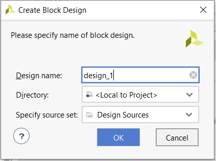
- Give your design a name and click on "OK".
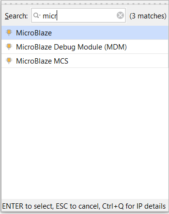
- Click on the '+' button ("Add IP") inside the Diagram window.
- Search "Microblaze" and insert it.
- You can double click on any IP in Vivado to customize it but we don't need it now.
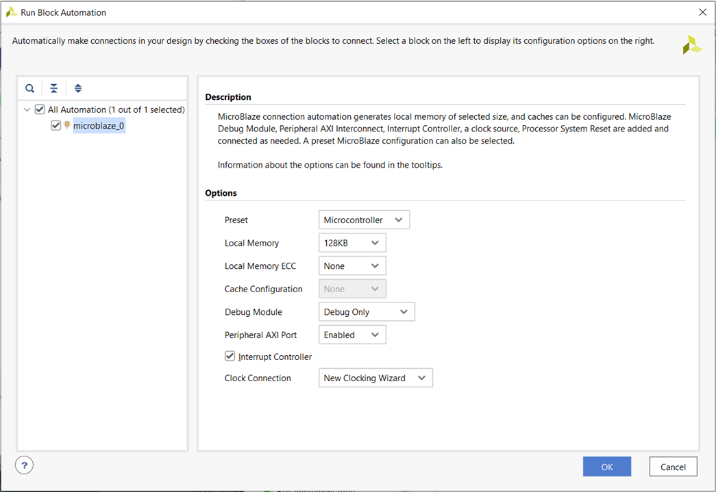
- Now, click on "Run Block Automation".
- In the "Run Block Automation" wizard, set the preset as "Microcontroller" and Local Memory to 128KB (it can be changed later as required). Click on "OK".
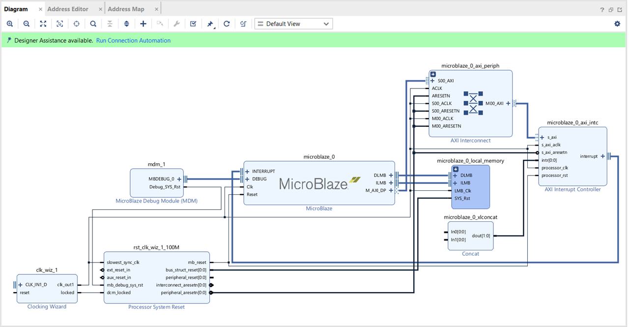
- All the important blocks will be automatically added and appropriately connected.
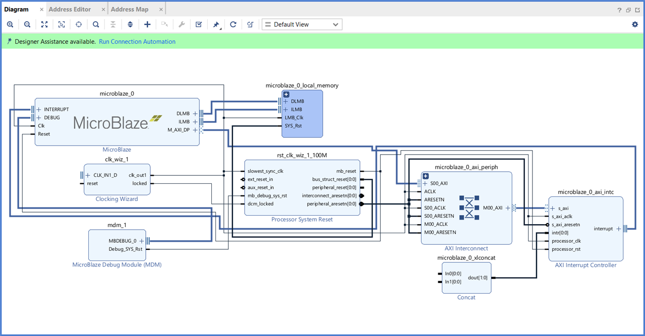
- There is an interesting button (looks like a refresh icon) in the Diagram window to regenerate the layout, pressing which will make it easier to read. All the inputs will be shifted towards the left side of the MicroBlaze IP and all the outputs on the right side.
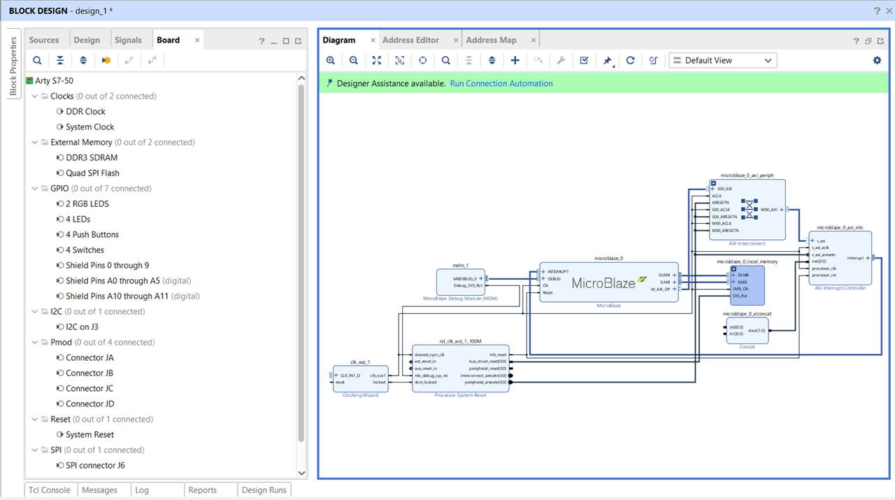
- There is a board tab available on the left side of the Diagram window. It lists all the components which are present on the chosen board. We can simply drag any component to our work area and use it in our project.
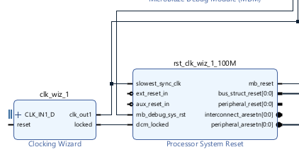
- The Arty S7-50 board uses active low reset but the clocking wizard has active high reset as shown below (bubble on the pin means its active low). So, we need to change it.
- To fix this, double click on the clocking wizard block.
- In the clocking wizard, go to the "Output clocks" tab, scroll down and select "Active Low" for Reset type. Click on "OK".
(This will insert a bubble on the reset pin of the clocking block)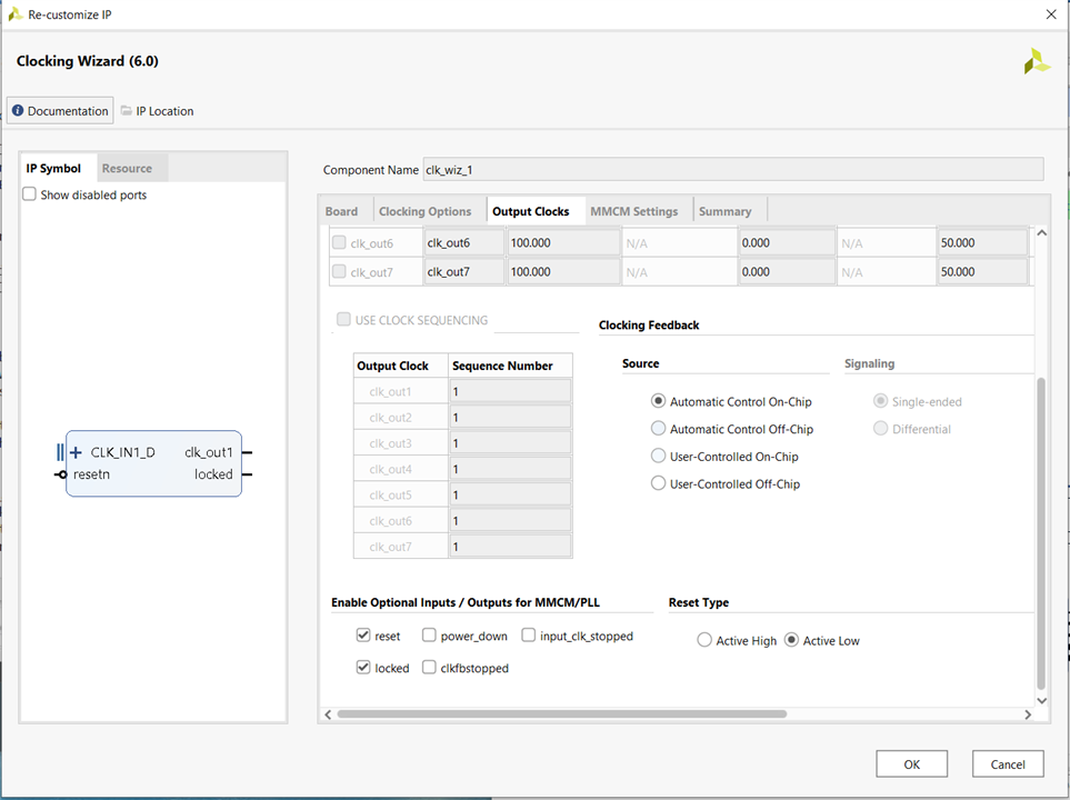
- Now, we need to add the "System Clock" from the "Board" menu to our Diagram. To do it just drag and drop these from the "Board" menu.
- Now, we need to add the "System Reset" from the "Board" menu to our Diagram. Click on "Run Connection Automation". A window will appear, select "All Automation" and click on "OK".
(We could have used the Connection Automation before also but since our board have two clocks - DDR Clock and System Clock, it would have inserted the DDR Clock but we needed System Clock that's why we had to drag and drop it).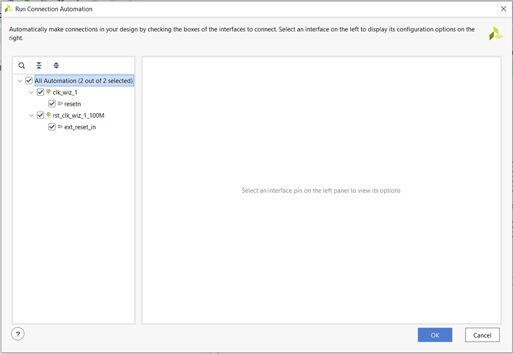
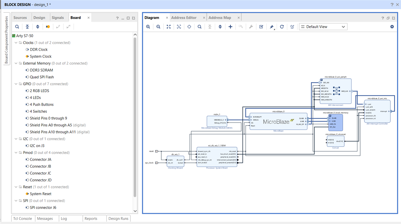
- Now our Diagram will look like something like shown below:
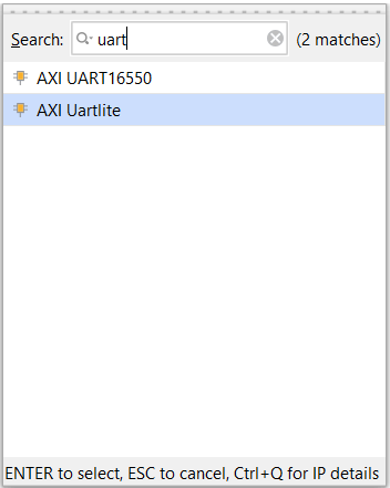
- Now, click on "Add IP" and add "AXI Uartlite" IP block for communication.
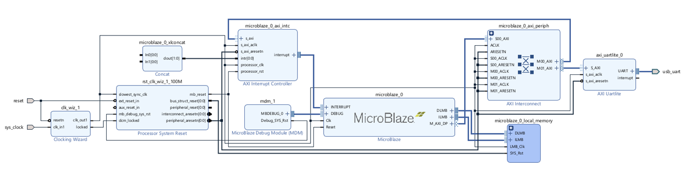
- Now, Run connection automation. Select "All Automation". Click on "OK".
- Our design will now look like this:
- Now add "4 LEDs" and "4 Push Buttons" from the Board menu to your Diagram and run connection automation. Regenerate the Layout.
- Your design will look like this:
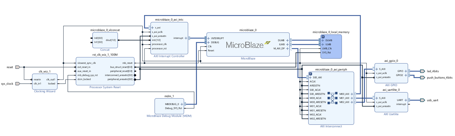
- You can validate your design by clicking on the "Validate Design" button inside the Diagram window (small tick icon).
- Now save your block design by clicking on the save button.
- Vivado needs to synthesize RTL. So, now we can create an HDL file from our Block Diagram.
- Go to the Sources tab, right click on the "design_1.bd" file and click on "Create HDL Wrapper". A window will open.
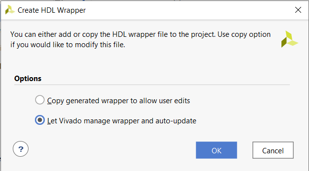
- The auto-update option means that if you make any changes to your Block Diagram, Vivado will automatically do the corresponding change in the HDL Wrapper file. Click on "OK".
- You can now see the HDL file for your design in the Sources tab.
- Now generate the bitstream for your design by clicking on "Generate Bitstream" in the left pane.
- Generating bitstream will take few minutes (around 10-20 mins), wait for it to complete. If it seems to be stuck click on cancel and try to generate it again.
- Now, we are done with Vivado. We have built the custom processor and the bitstream.
- We now need to move this file to our software development tool(Vitis).
- Go to File->Export->Export Hardware.
- Click on "Next".
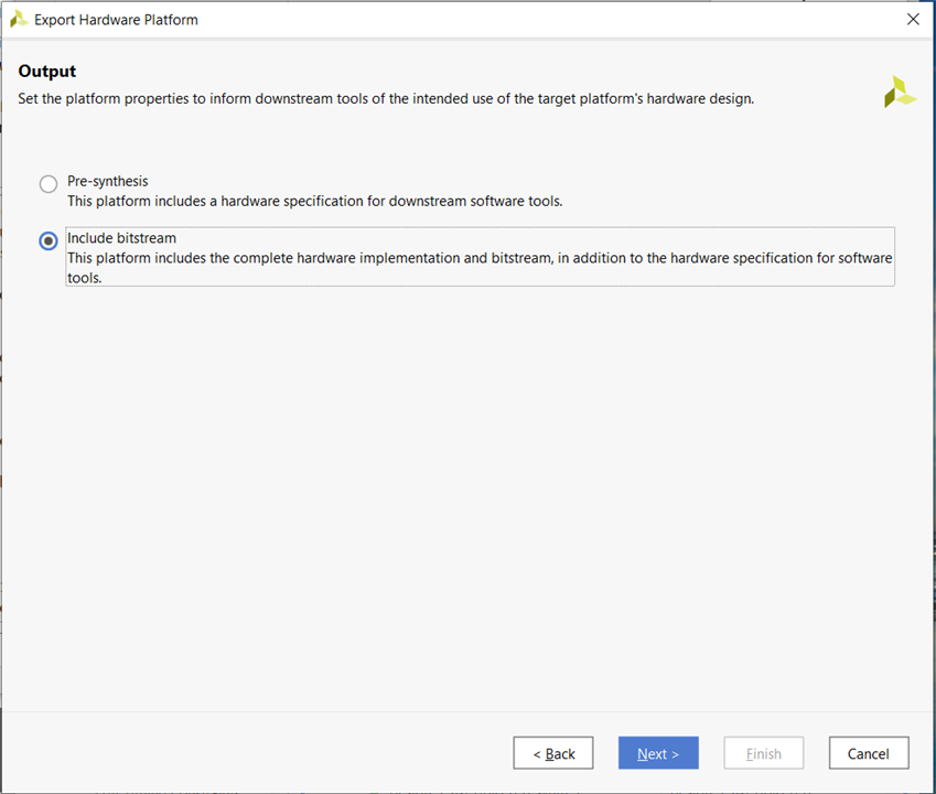
- Select "Include Bitstream". Click on "Next".
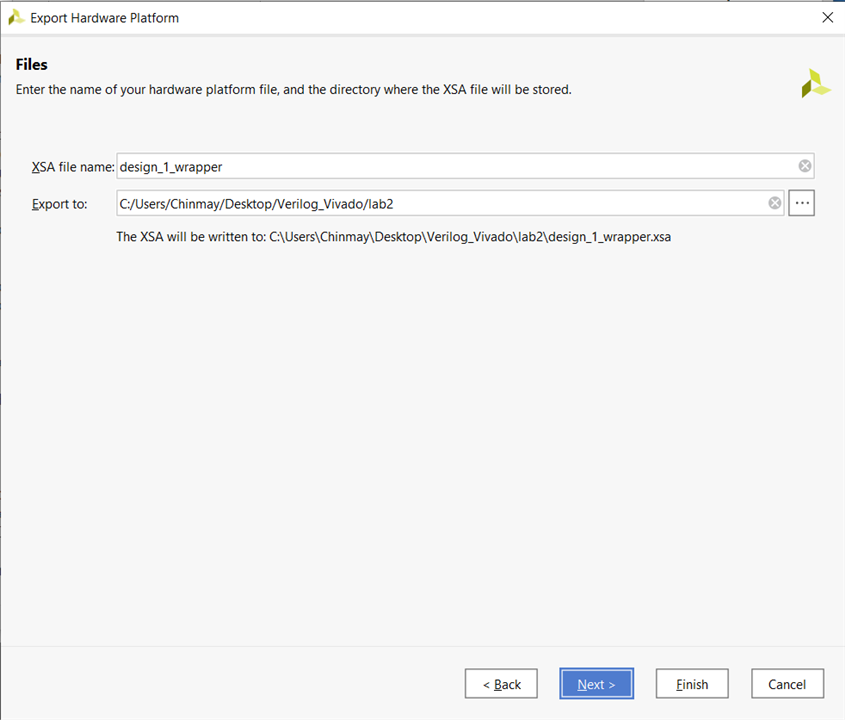
- You can change the name of your Hardware wrapper file (XSA file name) or just leave it as it is. Click on "Next".
- Click on "Finish".
- After the process finishes, go to "Tools" and click on "Launch Vitis IDE".
- You can close Vivado now.
Working on Vitis:
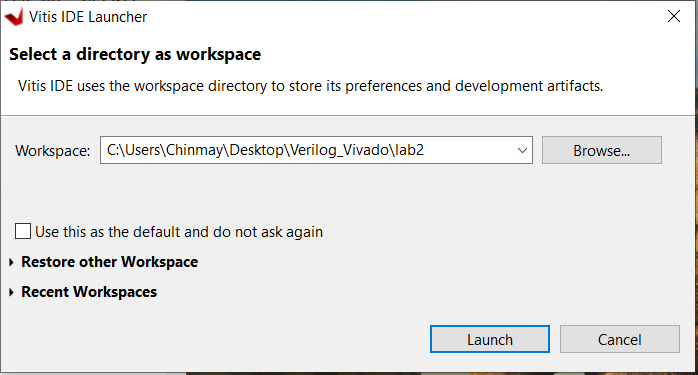
- After opening the Vitis IDE, select your workspace (your project folder) to open it. Click on "Launch".
- In the welcome window, click on "Create Application Project".
- Click on "Next".
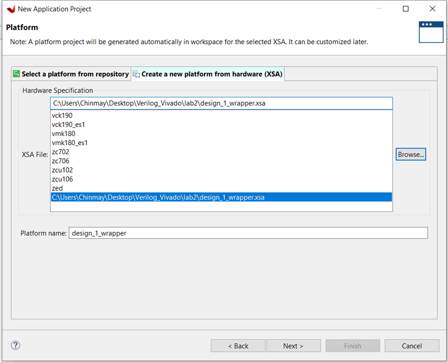
- Now, it will ask to choose a platform. Click on "Create a new platform from hardware". Browse the XSA file inside the project folder that we created in Vivado and select it. Click on "Next".
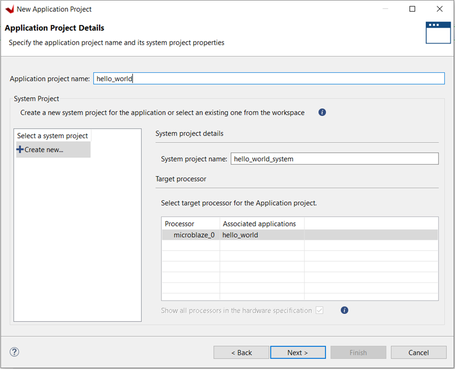
- Give your Application project a name. I have named it "hello_world". Click on "Next".
- Leave the defaults as it is. Click on "Next".
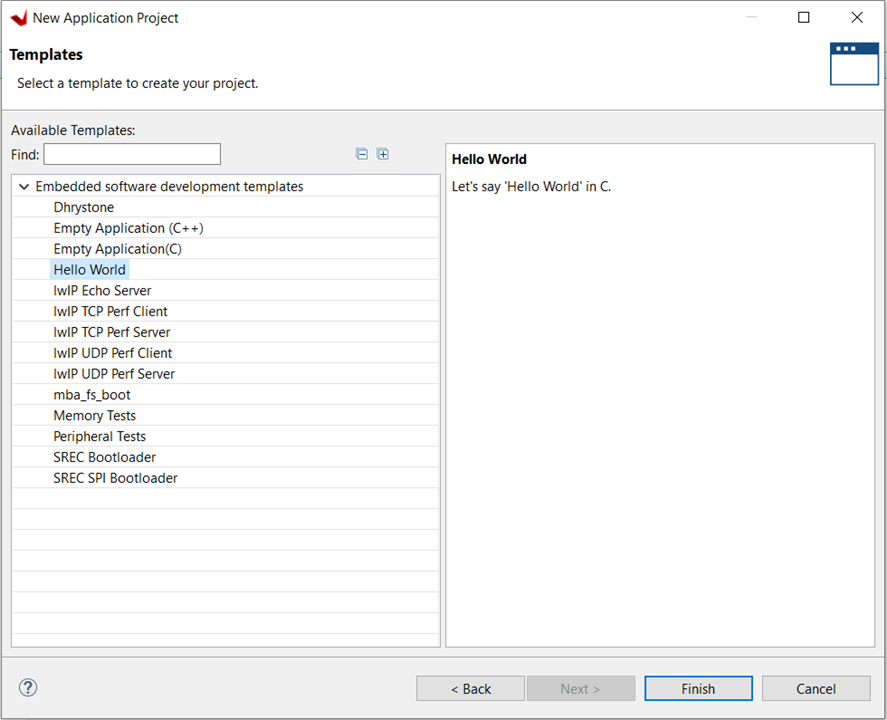
- Select the "Hello World" application template and click on "Finish".
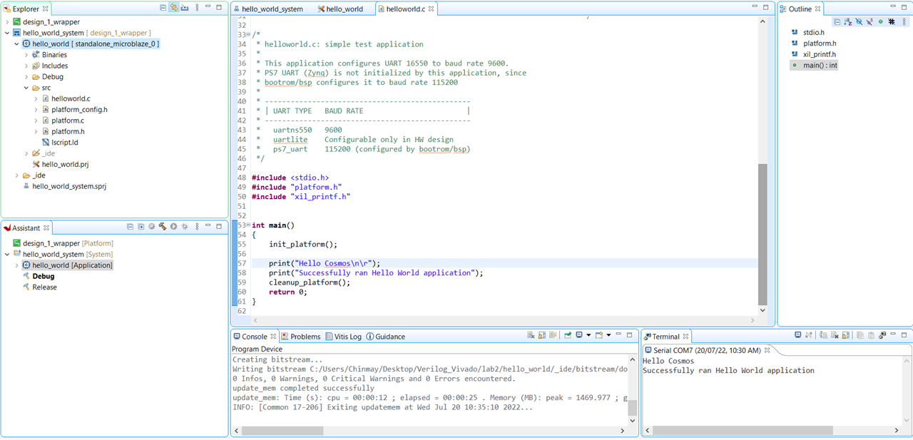
- Now, if you look at the "Explorer" tab on the left side, you will find "helloworld.c" file under the "src" drop down menu. Open this file.
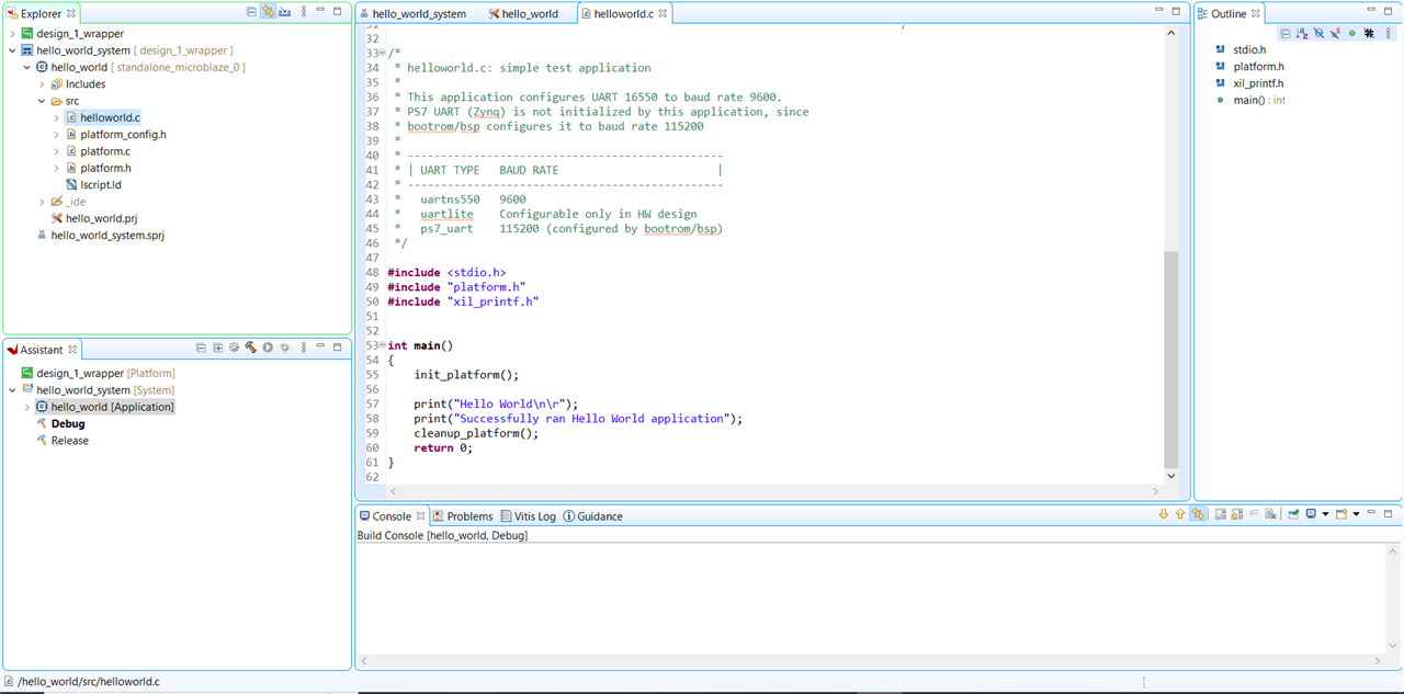
- You can modify this code according to your wish. You need to save it after modifying.
- Now, click on "Build" (hammer like icon) to build the project.
- You can now connect your board to the computer.
- The communication between the MicroBlaze and our computer will take place through the UART. We need a serial monitor for this.
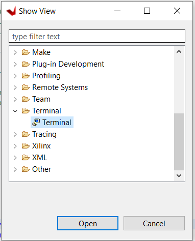
- After the build process finishes, go to Window->Show View.
- In the "Show View" window, go to "Terminal" drop down menu and select "Terminal". Click on "Open".
- A "Terminal" window will appear in the bottom right side of the screen.
- Now, click on "Open a Terminal" (monitor like icon) in the "Terminal" window.
- A "Launch Terminal" window will appear, in that select "Serial Terminal" and click on "OK".
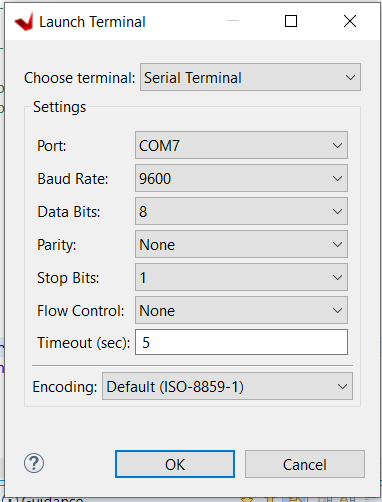
- This will open a serial terminal.
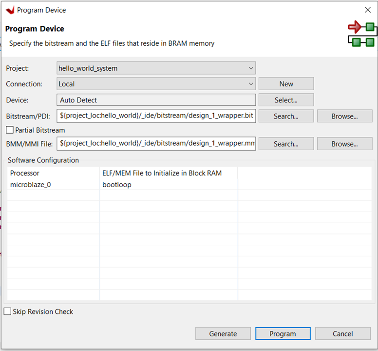
- Now we need to program our device. We could have done this earlier but we can do it from Vitis also. Just go to Xilinx->Program Device. This will open a window. Click on "Program".
- Now, to run our "helloworld.c" code on the board, just right click on "hello_world" in the "Explorer" tab, go to "Run As" and click on "Launch Hardware (Single Application Debug)".
- Now, if everything goes correct, you should be able to see your message (which you printed through your C code) in the terminal window.
Controlling LEDs and Push Buttons through C code:
- We had included LEDs and Push Buttons in our design. So, we can now try to do something with them.
- Create a new application project by going to File->New->Application Project.
- Click on "Next".
- Select the platform that we earlier created (design_1_wrapper.xsa). Click on "Next".
- Write the name of your Application Project. I have named mine as "LEDs". Click on "Next".
- Click on "Next".
- Select "Empty Application(C)". Click on "Finish".
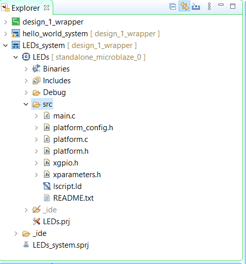
- Create a source file by right clicking on the "src" drop down menu, then click on "New", then click on "File". I have named my source file as "main.c".
- You will also need to copy some header files to your "src" folder. You can find these files in the "design_1_wrapper" drop down menu in the "Explorer" tab.
- Copy all the files as shown below.
- Now, copy the below given code in the source file and save it.
#include "xparameters.h" #include "xgpio.h" #include "xil_printf.h" /************************** Constant Definitions *****************************/ #define GPIO_DEVICE_ID XPAR_GPIO_0_DEVICE_ID #define LED_DELAY 1000000 #define LED_CHANNEL 1 #define BUTTON_CHANNEL 2 /**************************** Type Definitions *******************************/ XGpio Gpio; /* The Instance of the GPIO Driver */ int main() { int Status; int delay; int buttons = 0; int led = 0; /* Initialize the GPIO driver */ Status = XGpio_Initialize(&Gpio, GPIO_DEVICE_ID); if (Status != XST_SUCCESS) { xil_printf("Gpio Initialization Failed\r\n"); return XST_FAILURE; } /* Set data direction for LEDs (0 for input) and Push Buttons (1 for output) */ XGpio_SetDataDirection(&Gpio, LED_CHANNEL, 0b0000); XGpio_SetDataDirection(&Gpio, BUTTON_CHANNEL, 0b1111); while (1) { /* Read the Status of Buttons */ buttons = XGpio_DiscreteRead(&Gpio, BUTTON_CHANNEL); switch(buttons) { case 0b0001: led = 0b0001; break; case 0b0010: led = 0b0010; break; case 0b0100: led = 0b0100; break; case 0b1000: led = 0b1000; break; default: led = 0b0000; } /* Set the LED to High */ XGpio_DiscreteWrite(&Gpio, LED_CHANNEL, led); /* Wait a small amount of time so the LED is visible */ for(delay=0; delay<=LED_DELAY; delay++); } return 0; } - Click on "Build", then run it on the hardware. You will see the below mentioned functionality.
- When a push button is pressed, the corresponding LED will turn ON.
- When more than one push buttons are pressed simultaneously, all the LEDs will turn OFF.
Board Video:
Conclusion:
The block automation and the connection automation features made it very easy to build and connect the whole design correctly. The design can be easily transported between the Vivado and Vitis. The IP Integrator tool is a very good feature in Vivado which can be used to rapidly connect various IP blocks and with connection automation feature, it becomes very easy to implement our design in just a few minutes.
It takes a few minutes everytime I modify my C code and run it on the board. I wonder if there is some faster way to run the code!