


Introduction
Quite a long way back, I was fortunate enough to win a shopping basket in a Project 14 competition and the main item I purchased with it was an evaluation board for a Lattice iCE40UP5K FPGA device. Here, finally, is an informal look at that board and the device on it. As part of that, I'll do a small project to demonstrate the board being used.
What you get
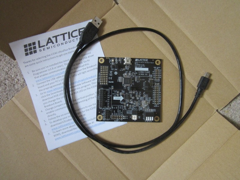
The evaluation board came in a plain cardboard box, wrapped in an antistatic bag which I now seem to have lost. You also get a USB cable and a single, printed sheet that acts as a quick-start guide to finding the design software and other documentation online. The box was folded and taped shut along the top, so, once you've opened it, it no longer functions as a storage box.
What you need
To use the particular FPGA on this board, with Lattice-supplied development tools, you'll need to install either iCEcube2 or Radiant. iCEcube2 is the legacy tool and Radiant is the more recent (and more capable) tool. I ended up using Radiant running on Xubuntu 22.04 for this review.
It is also possible to use open-source tools - there seems to be quite a lot of support for Lattice devices - but, as I don't have any experience of that, I'll stick to the official offering here.
Lattice tools are licensed, so you'll need to apply to them for a licence. Generally speaking, the non-SERDES parts (like this one) can use free-of-cost tools, where you are opting out of direct support, though iCEcube2 is now on a subscription for commercial use (still free for hobbyists and start-ups - see their licensing pages for details).
The Device
The device on the EVB is an iCE40UP5K FPGA. It's a low-cost part adding to a series of devices that originally would have been aimed at simple logic replacement and general interfacing duties. As well as the usual miniscule BGA packages, it's also available as an SG48I package which, although still an SMD part, may be more manageable for a personal project than the fine-pitch BGA parts.
The chip is particularly interesting because, with nearly 5k logic blocks, it is a moderately capable device and it has 16-bit hardware multipliers with accumulators [MACs], which would lend themselves to some simple DSP stuff. Obviously this is all relative, and it isn't going to compete head-on with much more capable high-end parts costing hundreds or even thousands of dollars, but the part itself does seem to me to be good value for money and a nice balance of capabilities.
Usefully, it also has two hard I2C and two hard SPI interfaces (one of the SPI interfaces is used for configuration).
What it won't give you, though, is masses of I/O. The packages are all small, with a limited number of pins.
The rest of the board hardware
The board is fairly minimalist and, in addition to the FPGA, carries a USB port, an FTDI chip for the device programming, a crystal oscillator (12MHz for the FTDI USB, which can also be routed to the FPGA as a clock), a serial flash memory for the bitstream, and linear regulators for the IO and core power. The board is a reasonable size (3" square), has sensibly-sized mounting holes at each corner, and has unpopulated placements for headers to bring out all the spare I/O. One of the headers is arranged as a PMOD interface, so populating that one would allow access to a wide range of IO boards. Given the price of the board, I thought it a little mean not to populate the headers (my Lattice Brevia 2 board came with the headers installed).
The worst thing about what was otherwise a neat and tidy board was that the one I received had the header holes full of solder. Getting solder out of the pin holes that were connected to the ground and power planes, using a hand solder-sucker, was painful.
Although I said the part itself was good value, whether the board is will depend on your situation. For a company, it probably represents less than an hour of design engineer time, and is the safe and quick way to evaluate the part if you aren't confident enough to go for an immediate prototype board: you can be reasonably sure it will function with their design tools and programming software. For a personal project, there will be lower cost options out there.
Project
For a simple project, I'm going to connect an audio fibre-optic transmitter to the board and send out a pair of sine waves calculated with the CORDIC component that I previously developed on an XP2 Brevia board. On the output side, this is basically PCM S/PDIF running over TOSlink. Porting the CORDIC component from XP2 to iCE40UP5K is easy: I just include it as a component in the new code and set the resolution generic appropriately - in this case to 16 bits (CD quality! Approximately. If I'm lucky and get it right). This will require me to develop a simple S/PDIF component for the output side. It's slightly artificial, and a bit limited unless you need a test box with only one, fixed function, but seems a reasonable amount of effort for a review and it could easily be developed further to be more useful. It also takes me a further step on towards doing some electronic music, which can't be a bad thing.
The hardware is fairly simple. The optical transmitter part works on 3.3V and can be driven by a single IO pin from the FPGA. Easy-peasy! As with the last couple of XP2 blogs, I'll also need an appropriate clock to derive the audio sample rate, so I've reused the xtal oscillator circuit I used there, with a logic gate for the gain element and a somewhat better choice of components than I used before around the 12.288MHz crystal.
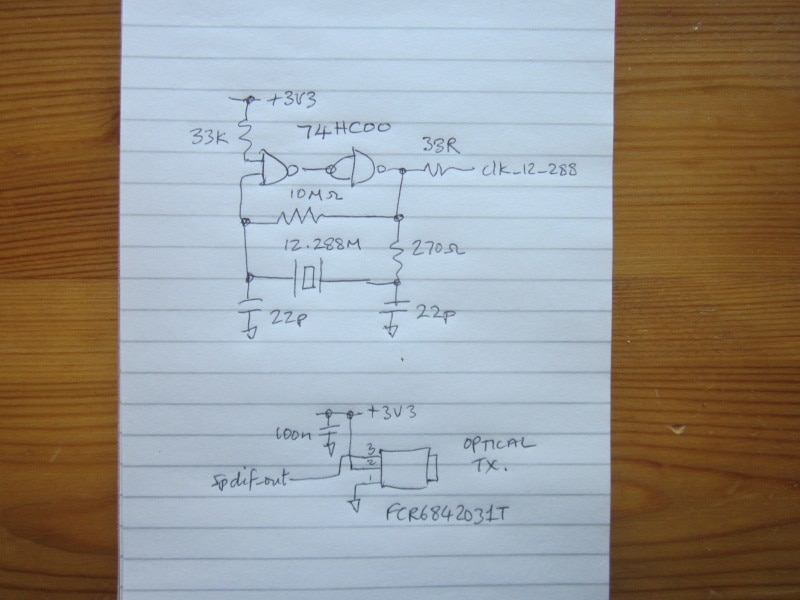
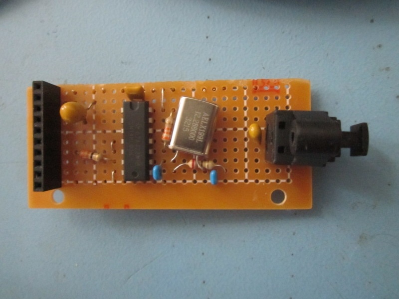
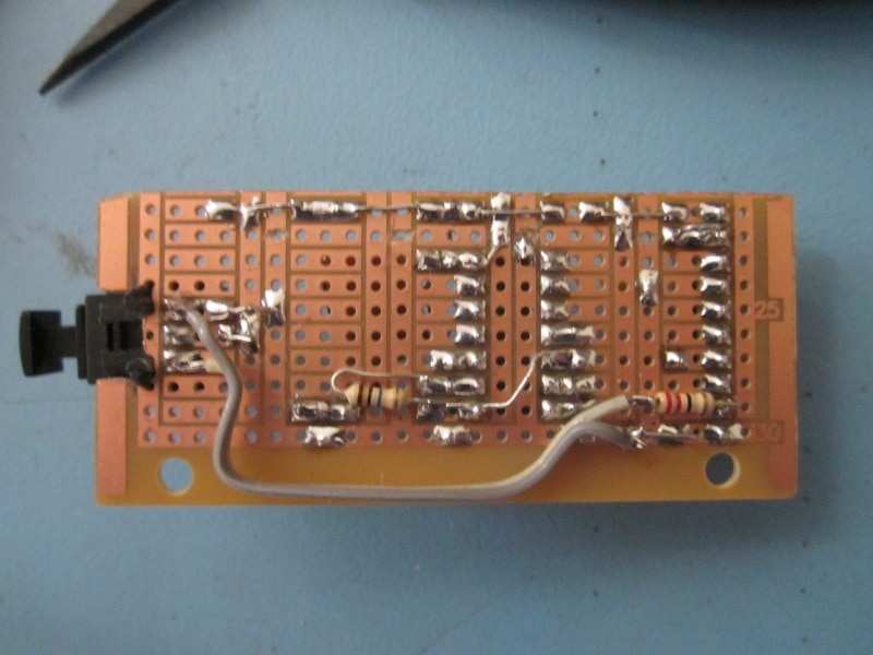
Here it is wired on a small prototyping board.
The S/PDIF Component
S/PDIF is a serial format that was developed jointly by Sony and Philips (hence the S/P part) back in the days of DAT (Digital Audio Tape). It subsequently got used for consumer equipment like CD players. Each frame at the sample rate has two subframes, each carrying a channel of audio at up to 24 bits of resolution, though it's usually used for no more that 20 and, in the case of CD, more normally 16. Along with the audio samples (usually a stereo pair), there's provision for control data and user data sent at a slower rate using single bits within the subframe. The physical interface is either coax (75R with RCA connectors) or plastic optical fibre (with the TOSlink-style transmitter and receiver parts).
As a quick aside, S/PDIF derived from a professional transport (AES3) that was developed by broadcasters. AES3 uses different physical interfaces and connectors - either XLR differential pair or BNC 75R coax - more in keeping with a professional studio environment: those two choices allowing use of existing analogue distribution networks for either audio or video. The AES3 spec is open and you can still download it for free from the EBU's website. S/PDIF was adopted by the IEC and so you pay for it, though I'm hoping that there's enough general info around for me to do what I'm doing here without paying thousands of dollars for the priviledge. S/PDIF mostly differs from AES3 in the way the control and user bits are used; the channel coding and the formatting of the audio and the synchronisation are the same as AES3. Because I don't have the actual standard, my implementation will be partial, and I'm going to simply try for enough functionalty to drive a small optical-to-analogue converter box. My main guides here are an old copy of The Art of Digital Audio by Williamson, which appears to cover S/PDIF fairly thoroughly, and the AES3 spec downloaded from the EBU website. If you were actually interested in AES3 itself, it should be straightforward to rework what I've done here for S/PDIF.
Because the interface was intended to work with different kinds of equipment there isn't a single, specified sample rate. Originally, it would have been used at 48ksps (DAT), and then 44.1ksps (CD). Commercial chips are likely work to at least 96k/88.4k and maybe even 192k. For what I'm doing here I'm going to work at 48ksps rather than 44.1ksps. Why? Because I have some 12.288MHz crystals (= 256 x 48kHz) that will work nicely to generate the S/PDIF serial bitstream.
The VHDL
Here's the HDL.
----------------------------------------------------------------------
--              ***** ice40up5k_evn_test.vhd *****                  --
--                                                                  --
-- Lattice ICE40UP5K evaluation board review test.                  --
-- Generates fixed pair of CORDIC 16-bit sine waves and formats     --
-- them for an S/PDIF serial optical link.                          --
--                                                                  --
----------------------------------------------------------------------
-- (C)2026 Jon Clift                                                --
-- Free to use however you want. No warranty as to correctness.     --
-- No guarantee of fitness for any purpose. No obligation to support--
----------------------------------------------------------------------
-- Rev    Date         Comments                                     --
-- 01     23-Feb-2026                                               --
----------------------------------------------------------------------

library ieee;
use ieee.std_logic_1164.all;
use ieee.numeric_std.all;
use ieee.math_real.all;

entity ice40up5k_evn_test is port(
    clk_12:            in STD_LOGIC;          --- system clock in (from 12MHz oscillator)
    clk_12_288:        in STD_LOGIC;          --- clock in (from my 12.288MHz oscillator)
    tp1:               out STD_LOGIC;        --- scope trigger at start of frame
    spdif_out:         out STD_LOGIC);        --- s/pdif data stream (to optical tx)
end ice40up5k_evn_test;

architecture arch_ice40up5k_evn_test of ice40up5k_evn_test is

constant sig_resol: POSITIVE := 16;                        --- signal resolution (bits)
constant pha_resol: POSITIVE := 32;                        --- phase resolution (bits)
signal theta: SIGNED(pha_resol-1 downto 0);                --- phase accumulator
signal theta_left: SIGNED(pha_resol-1 downto 0);           --- left phase accumulator
signal theta_right: SIGNED(pha_resol-1 downto 0);          --- right phase accumulator
signal phase_increment_left: SIGNED(pha_resol-1 downto 0); --- left phase increment
signal phase_increment_right: SIGNED(pha_resol-1 downto 0); --- right phase increment
signal sine: SIGNED(sig_resol-1 downto 0);                 --- CORDIC generated sine
signal cosine: SIGNED(sig_resol-1 downto 0);               --- CORDIC generaated cosine
signal sample_left: SIGNED(sig_resol-1 downto 0);               --- left sample
signal sample_right: SIGNED(sig_resol-1 downto 0);               --- right sample
signal delay_i: STD_LOGIC;                                 ---
signal delay_o: STD_LOGIC;                                 ---
signal delay_o_1: STD_LOGIC;                                 ---
signal spdif_clk_en: STD_LOGIC;                            ---
signal spdif_sample_en: STD_LOGIC;                         ---
signal sample_en_del1: STD_LOGIC;                         ---
signal sample_en_del2: STD_LOGIC;                         ---
signal prescale_count: UNSIGNED(1 downto 0);                 ---

--- declare the s/pdif output component

component spdif_out_component is
    generic(
        in_res: POSITIVE);           --- audio sample resolution
    port (
        clk_in: in STD_LOGIC;                           --- clock
        clk_en: in STD_LOGIC;                           --- clock enable
        l_data: in SIGNED(in_res-1 downto 0);           --- left audio data in
        r_data: in SIGNED(in_res-1 downto 0);           --- right audio data in
        next_sample_en: out STD_LOGIC;                 --- trigger sample update
        spdif_data_out: out STD_LOGIC);                 --- output bitstream
end component;

--- declare the CORDIC component

component cordic is
    generic(
        input_resol: POSITIVE;                     --- input resolution
        output_resol: POSITIVE);                   --- output resolution
    port(
        clk_in: in STD_LOGIC;                      --- clock in
        delay_in: in STD_LOGIC;                    --- delay in
        delay_out: out STD_LOGIC;                  --- delay out
        theta: in SIGNED(pha_resol-1 downto 0);    --- phase in
        sine: out SIGNED(sig_resol-1 downto 0);    --- sine out
        cosine: out SIGNED(sig_resol-1 downto 0)); --- cosine out
end component;

begin

    --- main process
    --- runs two phase accumulators, one for left and one for right
    --- CORDIC component calculates sine of each
    --- results stored and handed to spdif component for output formatting

    evb_test_stuff: process (clk_12_288) is
    begin

        if (clk_12_288'event and clk_12_288 = '1') then

            --- divide clock by 2 to run SPDIF at 6.144MHz for 48ksps

            if(spdif_clk_en = '0') then
                spdif_clk_en <= '1';
            else
                spdif_clk_en <= '0';
            end if;

            if (spdif_sample_en = '1') then
                theta_left <= theta_left + phase_increment_left;
                theta_right <= theta_right + phase_increment_right;
            end if;

            sample_en_del1 <= spdif_sample_en;
            sample_en_del2 <= sample_en_del1;

            if (spdif_sample_en = '1') then
                delay_i <= '1';
            elsif(sample_en_del2 = '1') then
                delay_i <= '0';
            end if;

            if (sample_en_del1 = '1') then
                theta <= theta_left;
            else
                theta <= theta_right;
            end if;

            delay_o_1 <= delay_o;

            if (delay_o = '1' and delay_o_1 = '0') then
                sample_left <= sine;
            end if;

            if (delay_o = '1' and delay_o_1 = '1') then
                 sample_right <= sine;
            end if;

        end if;

        phase_increment_left(31 downto 0) <= b"0000_0010_0101_1000_1011_1111_0010_0110";    --- 440Hz
        phase_increment_right(31 downto 0) <= b"0000_0010_0101_1001_0110_1101_1110_1001";   --- 440.5Hz


    end process evb_test_stuff;

    --- instantiate and connect the spdif output component

    spdif_1: component spdif_out_component
        generic map(
            in_res => sig_resol)  --- audio sample resolution
        port map(
            clk_in => clk_12_288,
            clk_en => spdif_clk_en,
            l_data => sample_left,
            r_data => sample_right,
            next_sample_en => spdif_sample_en,
            spdif_data_out => spdif_out);

    --- instantiate and connect the CORDIC component

    cordic_1: component cordic
        generic map(
            input_resol => pha_resol,  --- input resolution
            output_resol => sig_resol) --- output resolution
        port map(
            clk_in => clk_12_288,      --- clock in
            delay_in => delay_i,       --- delay in
            delay_out => delay_o,      --- delay out
            theta => theta,            --- phase in
            sine => sine,              --- sine out
            cosine => cosine);         --- cosine out

    tp1 <= spdif_sample_en;

end arch_ice40up5k_evn_test;
-------------------------------------------------------------------------------
-- cordic.vhd                                                                --
--                                                                           --
-- VHDL component to implement a fast, pipelined CORDIC sine                 --
-- and cosine calculation.                                                   --
--                                                                           --
-- Two generics specify the desired resolutions for input and output.        --
-- A delay chain sits alongside the CORDIC pipeline to relate the output to  --
-- the input.                                                                --
--                                                                           --
-- Developed for XP2 using LSE in Diamond 3.12, but fairly                   --
-- standard VHDL and no Lattice IP components so should work                 --
-- with any FPGA.                                                            --
--                                                                           --
-- Number of CORDIC stages is one more than the output resolution.           --
-- Internal data width is (output resolution * 1.25) + 3 bits.               --
--                                                                           --
-- More information at project page:                                         --
-- https://community.element14.com/technologies/fpga-group/b/blog/posts/fast-vhdl-cordic-sine-and-cosine-component-on-lattice-xp2-device-using-diamond-3-12                                                              --
-------------------------------------------------------------------------------
-- (c)2023 Jon Clift 7th April 2023                                          --
-- Free to use however you want. No warranty as to correctness.              --
-- No guarantee of fitness for any purpose. No obligation to support.        --
-------------------------------------------------------------------------------
-- Rev Date         Comments                                                 --
-- 01  31-Mar-2023  internally overflows with sin or cos close to 1          --
-- 02  07-Apr-2023  added extra bit of headroom                              --
-- 03  05-Nov-2023  added another bit to internal resolution                 --
-------------------------------------------------------------------------------

library ieee;
use ieee.std_logic_1164.all;
use ieee.numeric_std.all;
use ieee.math_real.all;

entity cordic is
    generic(
        input_resol: POSITIVE;                         --- input resolution
        output_resol: POSITIVE);                       --- output resolution
    port(
        clk_in: in STD_LOGIC;                          --- clock in
        delay_in: in STD_LOGIC;                        --- delay in
        delay_out: out STD_LOGIC;                      --- delay out
        theta: in SIGNED(input_resol-1 downto 0);      --- phase in
        sine: out SIGNED(output_resol-1 downto 0);     --- sine out
        cosine: out SIGNED(output_resol-1 downto 0));  --- cosine out
end entity cordic;

architecture arch_cordic of cordic is

--- declare the addsub component

component addsub is
    generic(
        resol: POSITIVE);                --- resolution (bits)
    port(
        clk_in: in STD_LOGIC;                --- clock in
        a: in SIGNED(resol-1 downto 0);      --- a in
        b: in SIGNED(resol-1 downto 0);      --- b in
        d: in STD_LOGIC;                     --- d=0 add, d=1 subtract
        s: out SIGNED(resol-1 downto 0));    --- sum out
end component addsub;

constant WORD_SIZE: POSITIVE := output_resol + (output_resol/4) + 3;

type MY_STD_LOGIC_ARRAY_TYPE is array(output_resol downto 0) of STD_LOGIC;
type MY_SIGNED_ARRAY_TYPE is array(output_resol downto 0) of SIGNED(WORD_SIZE-1 downto 0);

signal temp_phase: SIGNED(WORD_SIZE downto 0);
signal start_angle: SIGNED(WORD_SIZE-1 downto 0);
signal del: MY_STD_LOGIC_ARRAY_TYPE;
signal sin, cos, angle: MY_SIGNED_ARRAY_TYPE;
signal angle_coeff: MY_SIGNED_ARRAY_TYPE;
signal sin_start_value, cos_start_value, cos_start_value_p, cos_start_value_n: SIGNED(WORD_SIZE-1 downto 0);
signal initial_dir, not_initial_dir: STD_LOGIC;
signal dir, not_dir: MY_STD_LOGIC_ARRAY_TYPE;
signal shift_cos, shift_sin: MY_SIGNED_ARRAY_TYPE;

-- function to resize fractional binary numbers (note: numeric_std RESIZE doesn't work for this because the assumed binary point is down the other end)

function fractional_resize (arg: SIGNED; new_size: NATURAL) return SIGNED is
    variable result: SIGNED(new_size-1 downto 0) := (others => '0');
    begin
        if (new_size = arg'length) then
	        result := arg;
        end if;
        if (new_size < arg'length) then
            result(new_size-1 downto 0) := arg(arg'left downto arg'length - result'length);
        end if;
        if (new_size > arg'length) then
            result(new_size-1 downto new_size-result'length) := arg(arg'left downto 0);
        end if;
        return result;
    end fractional_resize;

-- now for the component code

begin

    temp_phase <= fractional_resize(theta,temp_phase'length);
    start_angle(start_angle'length-1 downto 0) <= temp_phase(temp_phase'length-2 downto 0);

    --- process to calculate the inverse-tangent coefficients and the overall gain (which will determine the cos start values)
    --- synthesis will understand to just calculate the values and then hardwire them into the final logic
    --- none of this floating-point calculation stuff will end up as logic in the FPGA

    calc_process: process
    variable temp: REAL;
    begin
        coeff_calc: for i in 0 to output_resol loop
            angle_coeff(i) <= to_signed(integer(round((2.0**real(WORD_SIZE-1)) * (arctan(2.0**(-1.0 * real(i))) / math_pi_over_2))),WORD_SIZE);
        end loop coeff_calc;
            temp := 1.0;
        gain_calc: for i in 0 to output_resol loop
            temp := temp * sqrt(1.0 + (2.0**(-2.0 * real(i))));
        end loop gain_calc;
            temp := (0.5 - (2.0**(-1.0 * real(output_resol-1))/2.0)) / temp;   --- adjustment to stop overflow (not very scientific!)
        cos_start_value_p <= to_signed(integer(trunc((2.0**real(WORD_SIZE-1)) * temp)),WORD_SIZE);
        cos_start_value_n <= to_signed(integer(trunc(-1.0 * (2.0**real(WORD_SIZE-1)) * temp)),WORD_SIZE);
            sin_start_value <= (others => '0');
        wait;
    end process calc_process;

--- now generate the logic for the cordic stages

    cordic_stages: for k in 0 to output_resol generate

    begin

        first_stage: if(k = 0) generate
        begin
            first_stage_process: process (clk_in,theta)
            begin
                if (clk_in'event and clk_in='1') then
                    del(0) <= delay_in;
                end if;
            end process;
            cos_start_value <= cos_start_value_p when ((theta(theta'length-1) xor theta(theta'length-2)) = '0') else cos_start_value_n;
            initial_dir <= theta(theta'length-2);
            not_initial_dir <= not theta(theta'length-2);
            addsub_1: component addsub generic map(resol => WORD_SIZE) port map(clk_in => clk_in, a => sin_start_value, b => cos_start_value, d => initial_dir, s => sin(0));
            addsub_2: component addsub generic map(resol => WORD_SIZE) port map(clk_in => clk_in, a => cos_start_value, b => sin_start_value, d => not_initial_dir, s => cos(0));
            addsub_3: component addsub generic map(resol => WORD_SIZE) port map(clk_in => clk_in, a => start_angle, b => angle_coeff(0), d => not_initial_dir, s => angle(0));
            end generate first_stage;

        other_stages: if(k /= 0) generate
        begin
            other_stages_process: process (clk_in)
            begin
                if (clk_in'event and clk_in='1') then
                    del(k) <= del(k-1);
                end if;
            end process;
            shift_cos(k) <= shift_right(cos(k-1),k);
            shift_sin(k) <= shift_right(sin(k-1),k);
            dir(k) <= angle(k-1)(WORD_SIZE-1);
            not_dir(k) <= not angle(k-1)(WORD_SIZE-1);
            addsub_4: component addsub generic map(resol => WORD_SIZE) port map(clk_in => clk_in, a => sin(k-1), b => shift_cos(k), d => dir(k), s => sin(k));
            addsub_5: component addsub generic map(resol => WORD_SIZE) port map(clk_in => clk_in, a => cos(k-1), b => shift_sin(k), d => not_dir(k), s => cos(k));
            addsub_6: component addsub generic map(resol => WORD_SIZE) port map(clk_in => clk_in, a => angle(k-1), b => angle_coeff(k), d => not_dir(k), s => angle(k));
            end generate other_stages;

    end generate cordic_stages;

    --- connect outputs to signals in design
    --- sine and cosine results need resizing (this is crude truncation)
    --- also need to exclude the additional overhead bit

    delay_out <= del(output_resol);
    sine(output_resol-1) <= sin(output_resol)(WORD_SIZE-1);
    sine(output_resol-2 downto 0) <= sin(output_resol)(WORD_SIZE-3 downto (WORD_SIZE-output_resol)-1);
    cosine(output_resol-1) <= cos(output_resol)(WORD_SIZE-1);
    cosine(output_resol-2 downto 0) <= cos(output_resol)(WORD_SIZE-3 downto (WORD_SIZE-output_resol)-1);

end arch_cordic;

-------------------------------------------------------------------------------
-- addsub                                                                    --
--                                                                           --
-- VHDL component to implement 2's complement add or subtract                --
-- no output carry                                                           --
-- registered output for the pipeline                                        --
-------------------------------------------------------------------------------
library ieee;
use ieee.std_logic_1164.all;
use ieee.numeric_std.all;

entity addsub is
    generic(
        resol: POSITIVE);                    --- desired resolution (bits)
    port(
        clk_in: in STD_LOGIC;                --- clock in
        a: in SIGNED(resol-1 downto 0);      --- a in
        b: in SIGNED(resol-1 downto 0);      --- b in
        d: in STD_LOGIC;                     --- d=0 add, d=1 subtract
        s: out SIGNED(resol-1 downto 0));    --- sum out
end entity addsub;

-- this version uses numeric_std addition and subtraction.
-- synthesis takes this literally, building both and placing a mux on the output to select the result
-- not good for space but synthesis knows how to use fast carry-chain logic to good advantage
-- I tried making a combined add-subtract component, but the performance was poor compared to this

architecture arch_addsub of addsub is

signal result: SIGNED(resol-1 downto 0):= (others => '0');

begin
    add_sub_process: process (clk_in)
    begin
        if (rising_edge(clk_in)) then
            if(d = '0') then
                result <= a + b;
            else
                result <= a - b;
            end if;
        end if;
    end process;
    s <= result;
end arch_addsub;
-------------------------------------------------------------------------------
-- spdif_out.vhd                                                             --
--                                                                           --
-- VHDL component to implement a simple S/PDIF output interface              --
--                                                                           --
-- Single generic specifies the desired resolution for the audio samples     --
--                                                                           --
-- Developed on Radiant for iCE40UP5K device.                                --
-- NOT A FULL IMPLEMENTATION: just enough to work with the fibre-to-DAC box  --
-- that I bought to experiment with.                                         --
-- Takes both audio samples (left and right) at same time, and sends back    --
-- next_sample_en to trigger calculation of the next pair.                   --
--                                                                           --
-------------------------------------------------------------------------------
-- (c)2026 Jon Clift 23th February 2026                                      --
-- Free to use however you want. No warranty as to correctness.              --
-- No guarantee of fitness for any purpose. No obligation to support.        --
-------------------------------------------------------------------------------
-- Rev Date         Comments                                                 --
-- 01  23-Feb-2026                                                           --
-------------------------------------------------------------------------------

library ieee;
use ieee.std_logic_1164.all;
use ieee.numeric_std.all;

entity spdif_out_component is
    generic(
        in_res: POSITIVE := 16);                        --- audio sample resolution (no more than 24)
    port(
        clk_in: in STD_LOGIC;                           --- clock in
        clk_en: in STD_LOGIC;                           --- clock enable
        l_data: in SIGNED(in_res-1 downto 0);           --- left audio data in
        r_data: in SIGNED(in_res-1 downto 0);           --- right audio data in
        next_sample_en: out STD_LOGIC;                  --- trigger next sample generation
        spdif_data_out: out STD_LOGIC);                 --- output
end entity spdif_out_component;

architecture arch_spdif_out_component of spdif_out_component is

---type UC_ARRAY_TYPE is array (0 to 511) of STD_LOGIC_VECTOR(1 downto 0);
---constant UC_ARRAY_DATA: UC_ARRAY_TYPE := (
---    b"00", b"00", b"00", b"00",b"00", b"00", b"00", b"00",b"00", b"00", b"00", b"00",b"00", b"00", b"00", b"00",
---    b"00", b"00", b"00", b"00",b"00", b"00", b"00", b"00",b"00", b"00", b"00", b"00",b"00", b"00", b"00", b"00",
---    b"00", b"00", b"00", b"00",b"00", b"00", b"00", b"00",b"00", b"00", b"00", b"00",b"00", b"00", b"00", b"00",
---    b"00", b"00", b"00", b"00",b"00", b"00", b"00", b"00",b"00", b"00", b"00", b"00",b"00", b"00", b"00", b"00",
---    b"00", b"00", b"00", b"00",b"00", b"00", b"00", b"00",b"00", b"00", b"00", b"00",b"00", b"00", b"00", b"00",
---    b"00", b"00", b"00", b"00",b"00", b"00", b"00", b"00",b"00", b"00", b"00", b"00",b"00", b"00", b"00", b"00",
---    b"00", b"00", b"00", b"00",b"00", b"00", b"00", b"00",b"00", b"00", b"00", b"00",b"00", b"00", b"00", b"00",
---    b"00", b"00", b"00", b"00",b"00", b"00", b"00", b"00",b"00", b"00", b"00", b"00",b"00", b"00", b"00", b"00",
---    b"00", b"00", b"00", b"00",b"00", b"00", b"00", b"00",b"00", b"00", b"00", b"00",b"00", b"00", b"00", b"00",
---    b"00", b"00", b"00", b"00",b"00", b"00", b"00", b"00",b"00", b"00", b"00", b"00",b"00", b"00", b"00", b"00",
---    b"00", b"00", b"00", b"00",b"00", b"00", b"00", b"00",b"00", b"00", b"00", b"00",b"00", b"00", b"00", b"00",
---    b"00", b"00", b"00", b"00",b"00", b"00", b"00", b"00",b"00", b"00", b"00", b"00",b"00", b"00", b"00", b"00",
---    b"00", b"00", b"00", b"00",b"00", b"00", b"00", b"00",b"00", b"00", b"00", b"00",b"00", b"00", b"00", b"00",
---    b"00", b"00", b"00", b"00",b"00", b"00", b"00", b"00",b"00", b"00", b"00", b"00",b"00", b"00", b"00", b"00",
---    b"00", b"00", b"00", b"00",b"00", b"00", b"00", b"00",b"00", b"00", b"00", b"00",b"00", b"00", b"00", b"00",
---    b"00", b"00", b"00", b"00",b"00", b"00", b"00", b"00",b"00", b"00", b"00", b"00",b"00", b"00", b"00", b"00",
---    b"00", b"00", b"00", b"00",b"00", b"00", b"00", b"00",b"00", b"00", b"00", b"00",b"00", b"00", b"00", b"00",
---    b"00", b"00", b"00", b"00",b"00", b"00", b"00", b"00",b"00", b"00", b"00", b"00",b"00", b"00", b"00", b"00",
---    b"00", b"00", b"00", b"00",b"00", b"00", b"00", b"00",b"00", b"00", b"00", b"00",b"00", b"00", b"00", b"00",
---    b"00", b"00", b"00", b"00",b"00", b"00", b"00", b"00",b"00", b"00", b"00", b"00",b"00", b"00", b"00", b"00",
---    b"00", b"00", b"00", b"00",b"00", b"00", b"00", b"00",b"00", b"00", b"00", b"00",b"00", b"00", b"00", b"00",
---    b"00", b"00", b"00", b"00",b"00", b"00", b"00", b"00",b"00", b"00", b"00", b"00",b"00", b"00", b"00", b"00",
---    b"00", b"00", b"00", b"00",b"00", b"00", b"00", b"00",b"00", b"00", b"00", b"00",b"00", b"00", b"00", b"00",
---    b"00", b"00", b"00", b"00",b"00", b"00", b"00", b"00",b"00", b"00", b"00", b"00",b"00", b"00", b"00", b"00",
---    b"00", b"00", b"00", b"00",b"00", b"00", b"00", b"00",b"00", b"00", b"00", b"00",b"00", b"00", b"00", b"00",
---    b"00", b"00", b"00", b"00",b"00", b"00", b"00", b"00",b"00", b"00", b"00", b"00",b"00", b"00", b"00", b"00",
---    b"00", b"00", b"00", b"00",b"00", b"00", b"00", b"00",b"00", b"00", b"00", b"00",b"00", b"00", b"00", b"00",
---    b"00", b"00", b"00", b"00",b"00", b"00", b"00", b"00",b"00", b"00", b"00", b"00",b"00", b"00", b"00", b"00",
---    b"00", b"00", b"00", b"00",b"00", b"00", b"00", b"00",b"00", b"00", b"00", b"00",b"00", b"00", b"00", b"00",
---    b"00", b"00", b"00", b"00",b"00", b"00", b"00", b"00",b"00", b"00", b"00", b"00",b"00", b"00", b"00", b"00",
---    b"00", b"00", b"00", b"00",b"00", b"00", b"00", b"00",b"00", b"00", b"00", b"00",b"00", b"00", b"00", b"00",
---    b"00", b"00", b"00", b"00",b"00", b"00", b"00", b"00",b"00", b"00", b"00", b"00",b"00", b"00", b"00", b"00");

constant A_PREAMBLE: STD_LOGIC_VECTOR := b"11100010";       --- 'A' ('X' for AES3) preamble pattern - subframe 1
constant B_PREAMBLE: STD_LOGIC_VECTOR := b"11100100";       --- 'B' ('Y' for AES3) preamble pattern - subframe 2
constant C_PREAMBLE: STD_LOGIC_VECTOR := b"11101000";       --- 'C' ('Z' for AES3) preamble pattern - subframe 1 & block start

signal half_bit_count: UNSIGNED(5 downto 0) := b"000000";       --- operate at twice the bit rate to suit the Manchester coding
signal subframe_count: UNSIGNED(8 downto 0) := b"000000000";    --- gives frame count by dropping lsb
signal temp_reg: STD_LOGIC_VECTOR(in_res-1 downto 0);           --- temp store for right audio data in
signal shift_reg: STD_LOGIC_VECTOR(31 downto 0) := X"00000000";  --- the main data shift register
signal preamble_shift_reg: STD_LOGIC_VECTOR(7 downto 0) := b"00000000";
signal tog_out: STD_LOGIC := '0';                                --- output after coding
signal next_sample, next_sample_del: STD_LOGIC := '0';
signal bi_phase_parity: STD_LOGIC_VECTOR(1 downto 0) := b"00";   --- very short shift register for parity

begin

    spdif_clocked_stuff: process (clk_in)
    begin

        if (clk_in'event and clk_in = '1') then
            if (clk_en = '1') then

                --- update the half_bit counter (counts 64 half bits, ie 32 full bits for the subframe)
                half_bit_count <= half_bit_count + 1;

				--- update subframe count (there are 192 full frames, so count is to give us 384 subframes)
                if (half_bit_count = b"111111") then
                    if(subframe_count = b"101111111") then
                        subframe_count <= "000000000";
                    else
                        subframe_count <= subframe_count + 1;
                    end if;
                end if;

                --- load or shift the preamble shift register
                if (half_bit_count(5 downto 0) = b"111111") then       --- load at start of subframe as halfbit count rolls over...
				    if (subframe_count(0) = '1') then
					    if(subframe_count(8 downto 1) = b"10111111") then        --- subframe 383 - ie next is 0
                           preamble_shift_reg(7 downto 0) <= C_PREAMBLE;
                       else
                           preamble_shift_reg(7 downto 0) <= A_PREAMBLE;
						end if;
                    else
                        preamble_shift_reg(7 downto 0) <= B_PREAMBLE;
                    end if;
                else                                           --- shift...
                    preamble_shift_reg(7 downto 1) <= preamble_shift_reg(6 downto 0);
                    preamble_shift_reg(0) <= '0';
                end if;

                --- LOAD or SHIFT the main shift register
                if (half_bit_count(5 downto 0) = b"111111") then       --- LOAD as halfbit count rolls over...
                    shift_reg(3 downto 0) <= b"0000";                  --- dummy bits - preamble will overlay
                    shift_reg(27-in_res downto 4) <= (others => '0');  --- set unused audio bits and aux bits to 0
                    if(subframe_count(0) = '0') then                   --- load audio sample depending on which subframe, sign bit always aligns with bit 27
                        shift_reg(27 downto 28-in_res) <= STD_LOGIC_VECTOR(l_data(in_res-1 downto 0));   --- left audio sample goes straight in s/r
                        temp_reg(in_res-1 downto 0) <= STD_LOGIC_VECTOR(r_data(in_res-1 downto 0));   --- right audio sample placed in temp reg
                        next_sample <= '1';                                                          --- trigger generation of next pair of samples
                    else
                        shift_reg(27 downto 28-in_res) <= temp_reg(in_res-1 downto 0);   --- move right audio sample from temp to s/r
                        next_sample <= '0';
                    end if;
                    shift_reg(28) <= '0';                               --- validity bit (0 = sample suitable for audio conversion)
                    shift_reg(29) <= '0';                               --- user bit (no user data, just fixed at 0)
                    shift_reg(30) <= '0';                               --- channel data bit (try with no channel status bits, just forced to 0)
---                    shift_reg(30 downto 29) <= UC_ARRAY_DATA(to_integer(frame_count(7 downto 0) & half_bit_count(6)));         --- user/channel data bits
                    shift_reg(31) <= '0';                               --- dummy parity bit - will get overlaid
                elsif (half_bit_count(0) = '1') then                    --- otherwise SHIFT on bit boundary...
                    shift_reg(30 downto 0) <= shift_reg(31 downto 1);
                    shift_reg(31) <= '0';
                    next_sample <= '0';
                else                                                    --- or hold on the other
                    next_sample <= '0';
                end if;

                --- do differential bi-phase modulation (Manchester encoding) on output of main s/r
                if(half_bit_count(5 downto 0) = b"111111") then         --- start subframe
                    tog_out <= '1';                                     ---    in such a way as to match the end of the preamble
                elsif(half_bit_count(0) = '1') then                     --- always toggle on bit boundary
                    tog_out <= not tog_out;
                else
                    if(shift_reg(0) = '1') then                         --- toggle on other edge if data 1
                        tog_out <= not tog_out;
                    end if;
                end if;

                --- load or shift the encoded parity
				--- (final state of bi-phase encoding determines the parity)
                if (half_bit_count(5 downto 0) = b"111101") then       --- load...
                    if(tog_out = '1') then
                        bi_phase_parity(1 downto 0) <= b"00";
                    else
                        bi_phase_parity(1 downto 0) <= b"10";
                    end if;
                else                                           --- shift...
                    bi_phase_parity(1) <= bi_phase_parity(0);
                    bi_phase_parity(0) <= '0';
                end if;

                --- mux to select either preamble, bi-phase data, or parity
                if(half_bit_count(5 downto 3) = "000") then
                    spdif_data_out <= preamble_shift_reg(7);    --- preamble data
                elsif(half_bit_count(5 downto 1) = "11111") then
                    spdif_data_out <= bi_phase_parity(1);    --- encoded parity data
                else
                    spdif_data_out <= tog_out;    --- biphase data
                end if;

            end if;

            --- reduce next_sample_en to a single clock width (not necessarily best place to do this)
            next_sample_del <= next_sample;
            if(next_sample = '1' and next_sample_del = '0') then
                next_sample_en <= '1';
            else
                next_sample_en <= '0';
            end if;
        end if;

    end process spdif_clocked_stuff;

end arch_spdif_out_component;
A couple of things about the SPDIF component may not be totally obvious.
The standard allows for the preambles to be inverted (in order to deal with a balanced link where the two sides are swapped). That's relevant for a receiver, which must be able to identify either sense, but for my transmitter I can simply choose one or other group.
Overall, the frame data is Manchester encoded, except for the preamble. That exception is deliberate in the design of the standard: the preamble breaks the encoding, so that's the way the receiver is sure that it's finding the boundaries and isn't being misled by a pattern occuring in the regular data. That makes the generation of the bitstream a little fiddly. The preamble can't go in the shift register with the frame data - instead I give it its own shift register and have a mux at the end to select between preamble and encoded frame data.
Further there's the issue of how to deal with the parity bit. I could have kept track of the parity and inserted it at the approprate time in place of the shift register data, but here I've done it a slightly different way. The effect of the parity bit (with encoding) is to bring the state of the output to the same point at the end of each frame, ready for the same polarity of preamble each time. That means we can use the final state of the encoded data stream, immediately before the parity bit, to determine which one of the two patterns that has to be output to get us to that frame end point (in effect, the Manchester encoding is working out the parity as it goes along for us and we just need to finish off the sequence). So the mux on the end expands to select either preamble, encoded data, or parity.
Although I started to implement the additional, slower-rate control and data bitstreams, I thought I'd give it a go without, in the hope the receiver could sort itself out from the bitstream alone.
Results
It works! (Sort of.)
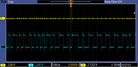
Here is the test output (a pulse marking the start of the frame that gives me something sensible to trigger on), and the SPDIF waveform around that point
Here are waveforms from the analogue outputs of the fibre-to-analogue box.
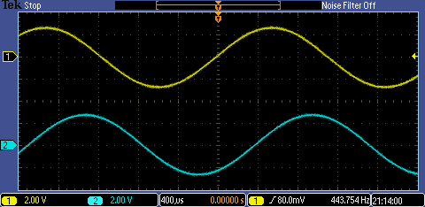
Because I've generated two sine waves, one on each channel, that are slightly different frequencies (one is 440.0Hz and the other 440.5Hz), if I trigger an oscilloscope on one, the other will run slowly past it, and the two will align every two seconds [reciprocal of 0.5Hz]. Here's a short video showing that happening.
So why 'sort of'?
The oscilloscope is having a real job trying to trigger on what is supposed to be a very simple, smooth, and precise waveform (a sine wave). Even with the trigger's HF Reject selected, it sometimes triggers on the wrong edge. That's because of all the noise. Here's a close up of what it's doing as it goes through the trigger point.
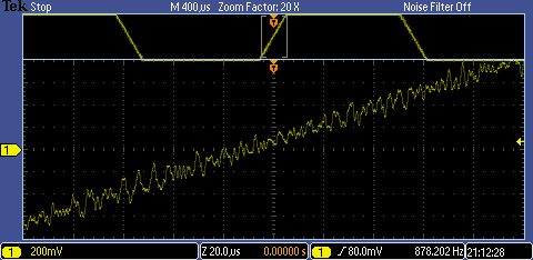
For what is supposed to be 16-bit audio it's pretty bad (that I can see it so obviously on the oscilloscope suggests it's not merely the DAC in the box dithering the lowest few bits). At the moment I've got no idea why, though it's suspiciously digital looking. It might be my CORDIC component, though the only change I made was reducing the resolution to 16 bits; it might be the SPDIF I'm generating - without the control stream the box may be misinterpreting it; it might be the optical link; or it might be to do with the way I'm looking at the signals with the oscilloscope.
Plenty of choice there for further investigation. Anyway, be cautious about using any of this in its current form. I'll update the blog when I finally sort it out.
Conclusions
Hopefully, that gives something of a feel for what is possible with the device. The CORDIC component, working 16 bits, and the SPDIF output component take up about two thirds of the part's resources, though the multipliers and the block RAMs are untouched.
This was my first time using Radiant and it was fine. It comes across as a rewrite of iCECube 2 with improvements for the various tools and I was able to use it straight away without any need to refer to the help files. The only problem I had was with the in-built programmer in Radiant. It failed on the verify of the serial flash on the board (judging from the messages, it looks like it runs one location past the end of the memory). The evaluation board programs fine using the standalone Diamond programmer, with the same bitstream file, so I worked with that instead of the Radiant one.
I haven't tried QuestaSim yet, but it installed ok and can be launched from within Radiant (the two components I originally developed in iCEcube 2 and simulated with ModelSim).
Further information
[1] https://www.latticesemi.com/en/Products/FPGAandCPLD/iCE40UltraPlus
[2] https://www.latticesemi.com/products/developmentboardsandkits/ice40ultraplusbreakoutboard
[3] https://uk.farnell.com/lattice-semiconductor/ice40up5k-b-evn/breakout-board-ice40-ultraplus/dp/3770328
[£71.32 + VAT each, Feb 2026]