


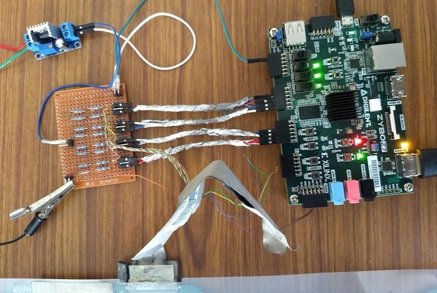
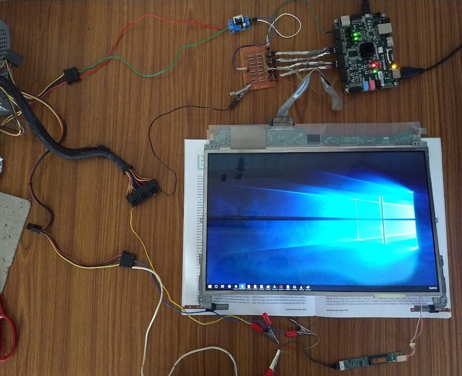
Continuing from where I left off in Driving a Laptop LCD using an FPGA, I moved the 'TMDS to LVDS converter board' to perf board, and soldered the differential pairs from the LCD panel onto it.
I used headers (to connect wires) for the connections between the converter board and FPGA's PMOD ports, but not that I think about it, it might have been better to solder the headers so that it could be plugged directly to a PMOD (or 2 PMODs) without using wires.

This setup was more stable, since there weren't any loose wires like when I used the breadboard. I also moved the project over to a Digilent Zybo Z7-20 because it has a HDMI RX port.
Implementing an HDMI Sink
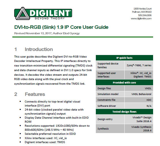
A HDMI sink is the reverse of what I worked on at Path to Programmable Blog 10 - MiniZed does DVI/HDMI. Digilent has published a dvi2rgb IP for Vivado, which takes DVI encoded video, and outputs the recovered pixel clock, RGB data and the sync signals. Another option would be bunnie's HDMI/DVI decoder for NeTV2 FPGA
| {gallery} Digilent's dvi2rgb |
|---|
Overview |
Block Diagram |
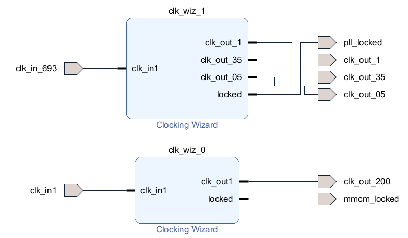
I imported the IP to a new Vivado Block Design, and made modifications to the clocks to support this. The IP requires a 200 Mhz input clock for internal control, but the rate at which it outputs data depends on the HDMI source (which is why it also outputs the recovered pixel clock).
The new clock block design uses a PLL (clk_wiz_1) to generate the 3 clocks needed to drive the LCD (pixel clock, serial clock & half clock) from the recovered pixel clock (clk_in_693 which comes from dvi2rgb).
clk_wiz_0 is used to generate the 200 Mhz reference clock from the 125Mhz clock connected to the Zybo Z7-20's PL.
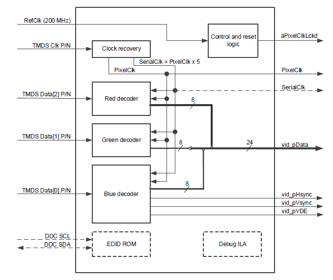
This is what the block design for the dvi2rgb IP looks like:


On the left the TMDS signals are the HDMI input, and on the right, you have the corresponding data & clock outputs. The SCL_x_y & SDA_x_y lines are I2C signals that are used to implement DDC, which is used to read EDID data (and implement HDCP). Due to how I2C works, the FPGA needs to use tri-state buffers, which is why there are 6 lines - inputs, outputs & tri-state buffer control. I also added an integrated logic analyzer core to aid debugging.
This is what my overall design looks like:
The MUXs are something that I also added for debugging - they allow me to switch the RGB data source between the 4 color bar pattern, and video coming over HDMI. Another set of muxes is used to select between the RGB & RBG HDMI data (I'll get to this a little later). The PL_Heartbeat block is some very simple code that uses a switch & some LED's - something that I can use to very that the clocks are active. I also drive another LED high when the dvi2rgb block locks onto the HDMI clock - to aid with debugging.

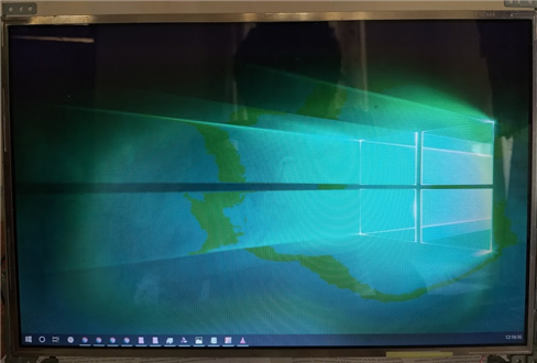
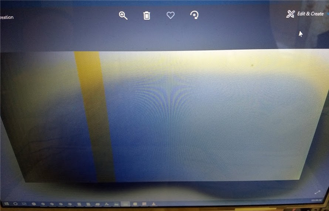
I programmed the FPGA, connected the HDMI port, and this showed up:
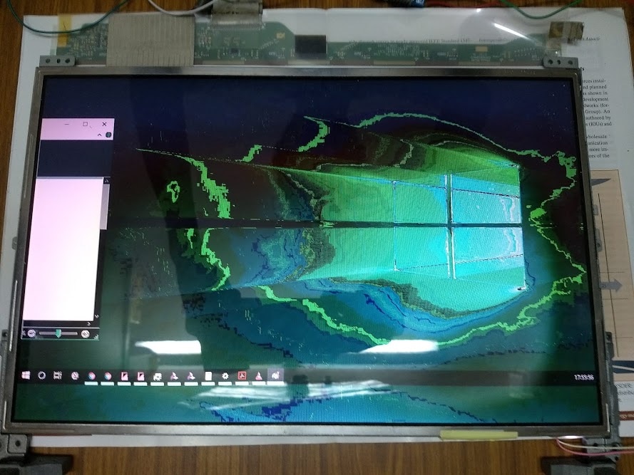
That's the iconic Windows 10 desktop wallpaper, except that the colors aren't.. correct. Note that the taskbar isn't at the bottom of the display - this is because the FPGA uses the default EDID data that Digilent bundles with the dvi2rgb IP, which was 1280x720. Since my rgb2lvds logic simply uses the data & sync signals it gets from dvi2rgb, and the LCD is 1280x800, it seems to plot the first 80 rows in rows 720 to 800. I noticed that if I tried moving the open window (windows explorer) further to the right, the display would skip frames, and if it was moved even further right, it would get more severe until the display went blank. I'm not sure why this happened, but I noticed that it occurred with certain color combinations which leads me to believe it's some kind of cross-talk/interference between the data channels.
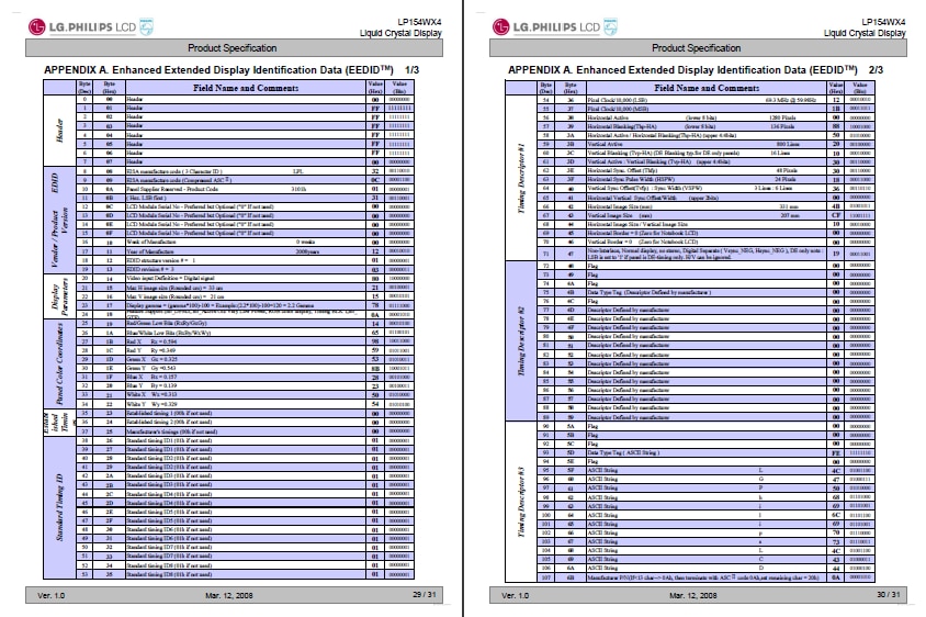
To fix the resolution issue, I would need to find a way let the HDMI source know the dimensions of the display, which would involve modifying the EDID. Digilent bundles 3 EDID profiles: 720p, 1024p & 1080p, but since they're formatted as ASCII text instead of raw binary, I couldn't use a EDID editor to make changes.
I resorted to manually changing the 720p EDID file to match the EDID data that was included at the end of the LCD panel's datasheet. I thought of writing a Python script to convert hexto ascii-formatted binary, but I remembered this and realized that this would be something that I'd do only once, so manually modifying it would be quicker.
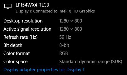
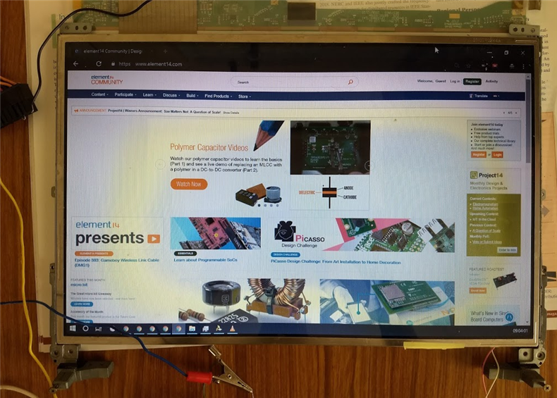
With this modification, Windows 10 correctly detects the display and sets the resolution correctly:
However, the colors weren't quite right:

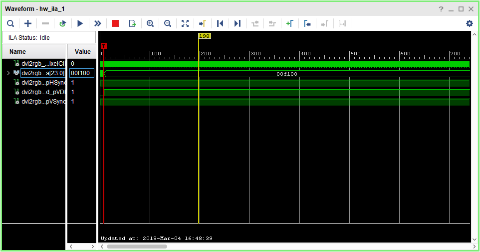
I downloaded a couple of test patterns, and created a couple of my own using Paint. After a while, I noticed that blues & greens were being swapped, so opened up a plain blue image (RGB 0,0,255) and used the Vivado Integrated Logic Analyzer to inspect the data that dvi2rgb was outputting - and this confirmed my theory of the swap. I added a mux (controlled by a switch) to allow me to select between swapped & un-swapped blue and green channels, and programmed the FPGA.
That corrected most of it, but there were still some artifacts. A grey scale test pattern showed me that certain shades of grey were being displayed as.. a tint of yellow. The shades in question were around RGB (65,65,65) to (80,80,80)
I also noticed that there were minor artifacts:
Touching the wires between the FPGA & converter board would cause distortion, and sometimes even make the artifacts go away - which meant that it was some kind of interference. Adding capacitors to the supply didn't help, and since the LVDS cable between the display & laptop motherboard was shielded in some kind of flexible metal foil, I figured that these guys were probably right - the wires needed some shielding.
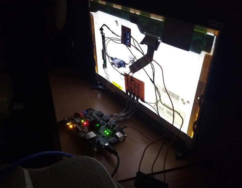
I wrapped some aluminum foil around the twisted pair cables.
The foil did help, and the display works without any noticeable artifacts (the yellow smudge is due to the TFT itself)
Everything mounted neatly on the back:
The foil is still loose, so I'll rewind it and connect it to the grounds. I also plan on moving a couple of other wires to perfboard so that this whole setup is easier to use.
The shielding needs to be improved for sure: turning on a tubelight causes the display to go black for a second.
I also want to try implementing HDMI RX on the MiniZed. I'll buy a breakout, terminate the differential lines to 3.3V, add a couple of other things to support Hot Plug Detect, and connect the differential lines to directly to the FPGA I/O.
The Zybo Z7 has a 'HDMI hider' on its HDMI RX, but the Arty Z7 doesn't (direct Zynq I/O termination), which means that it should be possible if the traces are kept short.
Things I plan on doing next:
- Generating an overlay
- Add alpha-blending support to the overlay
- Control & modify the overlay from the Zynq PS - I'll needto learn how to use AXI VDMA etc.
- Add support for audio
- Integrate the WS2812 controller I built with this to build an native 'universal' ambilight - which doesn't require any special software on the host. This shouldn't be too difficult: decode the HDMI stream and send filtered RGB data from pixels around the border of the display to the WS2812 LEDs.
Top Comments