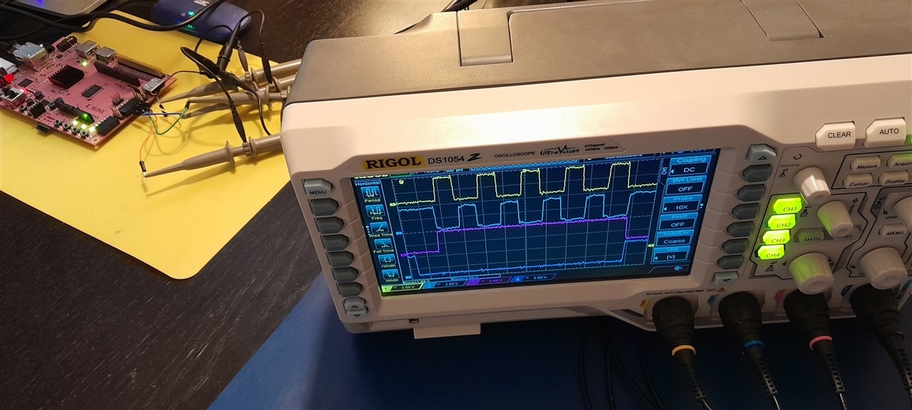
yepe has to resolve this problem for a project assignment:
|
Hi Jan Cumps, I hope you don't mind if I ask a question regarding the PYNQ half-bridge PWM driver. I am working on a student project for school and I need to drive a half-bridge for an ultrasound pulser. I was working through your great tutorial and I had the complementary pwm output on my board PYNQ Z1. However, I have to make certain changes to the operation to make it compatible with my needs which I attempted to do, but I could not determine the best approach. First off, I need to simplify that I only need 50% duty cycle and no other duty cycles needed. I have made a timing diagram for the various waveforms: CLK should be a continuous 20 MHz signal, PRF should be a 10 kHz 50% duty cycle signal that synchronizes the rest of the waveforms. PWM&PWMN are the complementary PWM signals with dead-time of programmable N cycles with a timed delay from a falling edge of PRF. PULSE should be equal to the length of the PWM pulse train, and GATE is equal to pulse but with a programmable delay. The PWM pulse-train should be 5 MHz. The first thing I tried to do is to change your example to see if I could get a 5 MHz complementary PWM but I could not see how the frequency is determined so I was playing around with the board clocks and only could get it up to 650 kHz. I am a biginner at vhdl so I am a bit out of my element. I have developed all the electronics and analogue demodulation circuits but I still lack the control system to tie it together. If I were to implement these signals in the PYNQ, where do you propose to start? |
My suggestion is to cut the task in simple(r) chunks:
|
I think that the easiest way to achieve this, as beginner, is to eat the elephant in pieces. Ignore my code, because it's not the basis for what you need.
The advantage of little steps is that you'll get early success, and that boosts the morale. The main job for each signal will will be to:
|
If you'd handle this different, comment below.
Capture of status after post 2:


Top Comments
-

Jan Cumps
-
Cancel
-
Vote Up
0
Vote Down
-
-
Sign in to reply
-
More
-
Cancel
-

yepe
in reply to Jan Cumps
-
Cancel
-
Vote Up
0
Vote Down
-
-
Sign in to reply
-
More
-
Cancel
-

Jan Cumps
in reply to yepe
-
Cancel
-
Vote Up
0
Vote Down
-
-
Sign in to reply
-
More
-
Cancel
-

michaelkellett
in reply to Jan Cumps
-
Cancel
-
Vote Up
+1
Vote Down
-
-
Sign in to reply
-
More
-
Cancel
-

Jan Cumps
in reply to Jan Cumps
-
Cancel
-
Vote Up
0
Vote Down
-
-
Sign in to reply
-
More
-
Cancel
-

Jan Cumps
in reply to michaelkellett
-
Cancel
-
Vote Up
0
Vote Down
-
-
Sign in to reply
-
More
-
Cancel
-

yepe
in reply to Jan Cumps
-
Cancel
-
Vote Up
0
Vote Down
-
-
Sign in to reply
-
More
-
Cancel
Comment-

yepe
in reply to Jan Cumps
-
Cancel
-
Vote Up
0
Vote Down
-
-
Sign in to reply
-
More
-
Cancel
Children