


Hii all,
This is me first time posting here on element14. I recently completed a Hardware Description of a part of a processor in Verilog. In this mini project, I ensured the datapaths, added 7 registers ( 6 normal and 1 special). The special register consists of two registers and a conditional adder block, so you can choose to perform addition/subtraction. For demonstration purposes, I did not make any program counter and machine state counter for the sake of simplicity. I have directly feeded the instructions to the microprocessor from the testbench.
Every instruction is of 11 bits, again for ease of interpretation, I did not encode the control bits in instruction. You can go ahead and decrease the length of instruction to 8-9 bits by putting a suitable decoder. Here is how each instruction is interpreted:
- bits instr[2:0] : Register Address 2
- bits instr[5:3] : Register Address 1
- inst[6] : if u want load a register (1 if loading is enabled else 0)
- inst[7] : f u want output to be connected to bus (1 if connected to bus else 0)
- inst[8] : if u want input to be connected to bus (1 if connected to bus else 0)
- inst[9] : choice of addition(0)/subtraction(1)
- inst[10] : loading the special register_adder block, for the first loading this bit should be 0, the next time you load it this bit should be 1
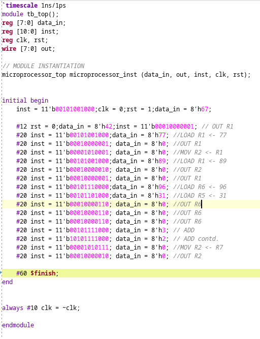
In the attached screenshot, read the instructions versus the comments written beside them
Here are the control instructions:
Here is the output: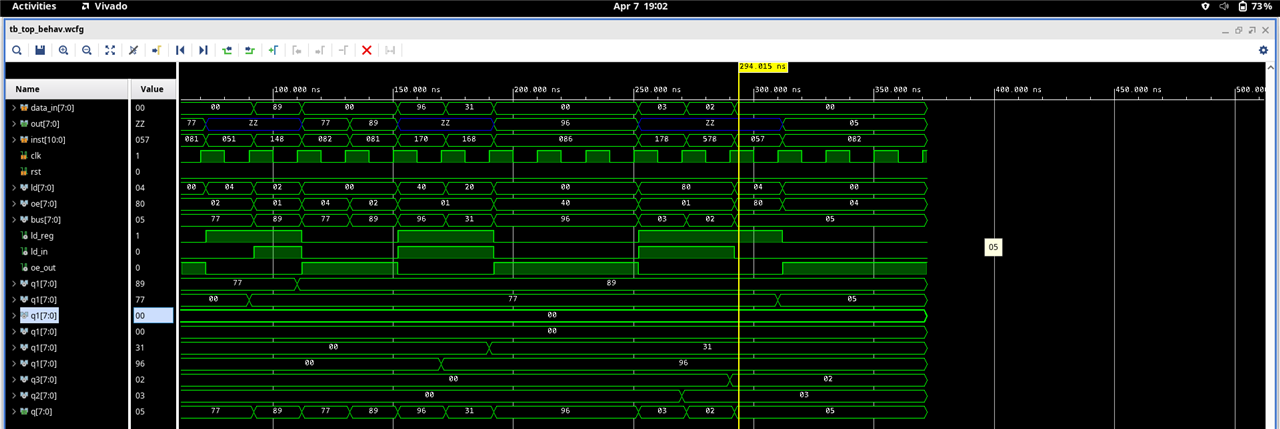
There could be several continuations to this project:
(i) If we want to make the writing of the test bench easier, we can write a python script to write the testbench from the assembly level instructions. eg, if we input MOV R2 <- R1, it should generate the following line: inst = 11'b00001010001; data_in = 8'h0;
(ii) To make a full RISC-V based processor, we will need to code the memory blocks, the Program counter and machine state blocks, this could be a very nice continuation from here.
I am attaching the whole code, where I have dumped all the modules along with the testbenches for you to run directly in Vivado/any other simulator. I highly recommend using Vivado as its extremely robust and stable.
Feel free to hit me up for any clarifications or if you want to share any cool ideas. Also like and comment...show some love (my first post here)
`timescale 1ns/1ps
module tb_top();
reg [7:0] data_in;
reg [10:0] inst;
reg clk, rst;
wire [7:0] out;

// MODULE INSTANTIATION
microprocessor_top microprocessor_inst (data_in, out, inst, clk, rst);


initial begin
    inst = 11'b00101001000;clk = 0;rst = 1;data_in = 8'h67;

    #12 rst = 0;data_in = 8'h42;inst = 11'b00010000001; // OUT R1
    #20 inst = 11'b00101001000;data_in = 8'h77; //LOAD R1 <- 77
    #20 inst = 11'b00010000001; data_in = 8'h0; //OUT R1
    #20 inst = 11'b00001010001; data_in = 8'h0; //MOV R2 <- R1
    #20 inst = 11'b00101001000;data_in = 8'h89; //LOAD R1 <- 89
    #20 inst = 11'b00010000010; data_in = 8'h0; //OUT R2
    #20 inst = 11'b00010000001; data_in = 8'h0; //OUT R1
    #20 inst = 11'b00101110000;data_in = 8'h96; //LOAD R6 <- 96
    #20 inst = 11'b00101101000;data_in = 8'h31; //LOAD R5 <- 31
    #20 inst = 11'b00010000110; data_in = 8'h0; //OUT R6
    #20 inst = 11'b00010000110; data_in = 8'h0; //OUT R6
    #20 inst = 11'b00010000110; data_in = 8'h0; //OUT R6
    #20 inst = 11'b00101111000; data_in = 8'h3; //LOAD R7 <- 3
    #20 inst = 11'b10101111000; data_in = 8'h2;
    #20 inst = 11'b00001010111; data_in = 8'h0; //MOV R2 <- R7
    #20 inst = 11'b00010000010; data_in = 8'h0; //OUT R2

    #60 $finish;
end


always #10 clk = ~clk;
endmodule

module microprocessor_top (input wire [7:0] data_in, output wire [7:0] out, input wire [10:0] inst, input wire clk, input wire rst);
wire [7:0] ld, oe, bus;
wire ld_reg,decod_enable,ld_in, oe_out;
assign ld_which = inst[10];
assign add_sub = inst[9];
assign ld_in = inst[8]; //if u want input to be connected to bus
assign oe_out = inst[7]; //if u want output to be connected to bus
assign ld_reg = inst[6]; //if u want load a register
assign decod_enable = 1'b1;

decoder3to8 decod1 (ld,inst[5:3],ld_reg);
decoder3to8 decod2 (oe,inst[2:0],decod_enable); // this is somewhat correct

bufif1 b20(bus[0],data_in[0],ld_in);
bufif1 b21(bus[1],data_in[1],ld_in);
bufif1 b22(bus[2],data_in[2],ld_in);
bufif1 b23(bus[3],data_in[3],ld_in);
bufif1 b24(bus[4],data_in[4],ld_in);
bufif1 b25(bus[5],data_in[5],ld_in);
bufif1 b26(bus[6],data_in[6],ld_in);
bufif1 b27(bus[7],data_in[7],ld_in);

bufif1 b30(out[0],bus[0],oe_out);
bufif1 b31(out[1],bus[1],oe_out);
bufif1 b32(out[2],bus[2],oe_out);
bufif1 b33(out[3],bus[3],oe_out);
bufif1 b34(out[4],bus[4],oe_out);
bufif1 b35(out[5],bus[5],oe_out);
bufif1 b36(out[6],bus[6],oe_out);
bufif1 b37(out[7],bus[7],oe_out);

reg_8bit R1(bus,clk,rst,oe[1],ld[1],bus);
reg_8bit R2(bus,clk,rst,oe[2],ld[2],bus);
reg_8bit R3(bus,clk,rst,oe[3],ld[3],bus);
reg_8bit R4(bus,clk,rst,oe[4],ld[4],bus);
reg_8bit R5(bus,clk,rst,oe[5],ld[5],bus);
reg_8bit R6(bus,clk,rst,oe[6],ld[6],bus);
reg_8bit_adder R7(bus,clk,rst,oe[7],ld[7],add_sub, ld_which, bus);
// Lets say R7 is our accumulator
endmodule

// 3 TO 8 DECODER ( DONE )
module decoder3to8 (output [7:0] O,input [2:0]  I,input  enable);

wire [7:0] O1;

not G0(enable2_4, I[2]);
decoder_2to4 dec1 (O1[3:0], I[1:0], enable2_4);
decoder_2to4 dec2 (O1[7:4], I[1:0], I[2]);
and G1 (O[0], O1[0], enable);
and G2 (O[1], O1[1], enable);
and G3 (O[2], O1[2], enable);
and G4 (O[3], O1[3], enable);
and G5 (O[4], O1[4], enable);
and G6 (O[5], O1[5], enable);
and G7 (O[6], O1[6], enable);
and G8 (O[7], O1[7], enable);

endmodule

module reg_8bit_adder (input [7:0] data_in, input clk, input rst, input enable_out, input enable_load,input add_sub,input ld_which, output [7:0] q);

wire [7:0] qbar2, qbar3,q1,q3,q2,data_in1,inbuff_out,inbuff_out2, d4, d5;

bufif1 b0(q[0],q1[0],enable_out);
bufif1 b1(q[1],q1[1],enable_out);
bufif1 b2(q[2],q1[2],enable_out);
bufif1 b3(q[3],q1[3],enable_out);
bufif1 b4(q[4],q1[4],enable_out);
bufif1 b5(q[5],q1[5],enable_out);
bufif1 b6(q[6],q1[6],enable_out);
bufif1 b7(q[7],q1[7],enable_out);

bufif1 b00(inbuff_out[0],data_in[0],enable_load & ld_which);
bufif1 b01(inbuff_out[1],data_in[1],enable_load & ld_which);
bufif1 b02(inbuff_out[2],data_in[2],enable_load & ld_which);
bufif1 b03(inbuff_out[3],data_in[3],enable_load & ld_which);
bufif1 b04(inbuff_out[4],data_in[4],enable_load & ld_which);
bufif1 b05(inbuff_out[5],data_in[5],enable_load & ld_which);
bufif1 b06(inbuff_out[6],data_in[6],enable_load & ld_which);
bufif1 b07(inbuff_out[7],data_in[7],enable_load & ld_which);


bufif1 b20(inbuff_out2[0],data_in[0],enable_load & ~ld_which);
bufif1 b21(inbuff_out2[1],data_in[1],enable_load & ~ld_which);
bufif1 b22(inbuff_out2[2],data_in[2],enable_load & ~ld_which);
bufif1 b23(inbuff_out2[3],data_in[3],enable_load & ~ld_which);
bufif1 b24(inbuff_out2[4],data_in[4],enable_load & ~ld_which);
bufif1 b25(inbuff_out2[5],data_in[5],enable_load & ~ld_which);
bufif1 b26(inbuff_out2[6],data_in[6],enable_load & ~ld_which);
bufif1 b27(inbuff_out2[7],data_in[7],enable_load & ~ld_which);

d_ff dff20(clk,rst,d4[0],q2[0],qbar2[0]);
d_ff dff21(clk,rst,d4[1],q2[1],qbar2[1]);
d_ff dff22(clk,rst,d4[2],q2[2],qbar2[2]);
d_ff dff23(clk,rst,d4[3],q2[3],qbar2[3]);
d_ff dff24(clk,rst,d4[4],q2[4],qbar2[4]);
d_ff dff25(clk,rst,d4[5],q2[5],qbar2[5]);
d_ff dff26(clk,rst,d4[6],q2[6],qbar2[6]);
d_ff dff27(clk,rst,d4[7],q2[7],qbar2[7]);

d_ff dff0(clk,rst,d5[0],q3[0],qbar3[0]);
d_ff dff1(clk,rst,d5[1],q3[1],qbar3[1]);
d_ff dff2(clk,rst,d5[2],q3[2],qbar3[2]);
d_ff dff3(clk,rst,d5[3],q3[3],qbar3[3]);
d_ff dff4(clk,rst,d5[4],q3[4],qbar3[4]);
d_ff dff5(clk,rst,d5[5],q3[5],qbar3[5]);
d_ff dff6(clk,rst,d5[6],q3[6],qbar3[6]);
d_ff dff7(clk,rst,d5[7],q3[7],qbar3[7]);

mux2to1 mux210 ({inbuff_out2[0],q2[0]},enable_load & ~ld_which,d4[0]);
mux2to1 mux211 ({inbuff_out2[1],q2[1]},enable_load & ~ld_which,d4[1]);
mux2to1 mux212 ({inbuff_out2[2],q2[2]},enable_load & ~ld_which,d4[2]);
mux2to1 mux213 ({inbuff_out2[3],q2[3]},enable_load & ~ld_which,d4[3]);
mux2to1 mux214 ({inbuff_out2[4],q2[4]},enable_load & ~ld_which,d4[4]);
mux2to1 mux215 ({inbuff_out2[5],q2[5]},enable_load & ~ld_which,d4[5]);
mux2to1 mux216 ({inbuff_out2[6],q2[6]},enable_load & ~ld_which,d4[6]);
mux2to1 mux217 ({inbuff_out2[7],q2[7]},enable_load & ~ld_which,d4[7]);

mux2to1 mux110 ({inbuff_out[0],q3[0]},enable_load & ld_which,d5[0]);
mux2to1 mux111 ({inbuff_out[1],q3[1]},enable_load & ld_which,d5[1]);
mux2to1 mux112 ({inbuff_out[2],q3[2]},enable_load & ld_which,d5[2]);
mux2to1 mux113 ({inbuff_out[3],q3[3]},enable_load & ld_which,d5[3]);
mux2to1 mux114 ({inbuff_out[4],q3[4]},enable_load & ld_which,d5[4]);
mux2to1 mux115 ({inbuff_out[5],q3[5]},enable_load & ld_which,d5[5]);
mux2to1 mux116 ({inbuff_out[6],q3[6]},enable_load & ld_which,d5[6]);
mux2to1 mux117 ({inbuff_out[7],q3[7]},enable_load & ld_which,d5[7]);


adder_8bit a1(q2, q3, q1, add_sub);

endmodule

// 8 BIT DATA REGISTER ( PARALLEL LOAD ) (DONE)

module reg_8bit (input [7:0] data_in, input clk, input rst, input enable_out, input enable_load, output [7:0] q);

wire [7:0] qbar,q1,data_in1,inbuff_out;

bufif1 b0(q[0],q1[0],enable_out);
bufif1 b1(q[1],q1[1],enable_out);
bufif1 b2(q[2],q1[2],enable_out);
bufif1 b3(q[3],q1[3],enable_out);
bufif1 b4(q[4],q1[4],enable_out);
bufif1 b5(q[5],q1[5],enable_out);
bufif1 b6(q[6],q1[6],enable_out);
bufif1 b7(q[7],q1[7],enable_out);

bufif1 b00(inbuff_out[0],data_in[0],enable_load);
bufif1 b01(inbuff_out[1],data_in[1],enable_load);
bufif1 b02(inbuff_out[2],data_in[2],enable_load);
bufif1 b03(inbuff_out[3],data_in[3],enable_load);
bufif1 b04(inbuff_out[4],data_in[4],enable_load);
bufif1 b05(inbuff_out[5],data_in[5],enable_load);
bufif1 b06(inbuff_out[6],data_in[6],enable_load);
bufif1 b07(inbuff_out[7],data_in[7],enable_load);

mux2to1 mux110 ({inbuff_out[0],q1[0]},enable_load,data_in1[0]);
mux2to1 mux111 ({inbuff_out[1],q1[1]},enable_load,data_in1[1]);
mux2to1 mux112 ({inbuff_out[2],q1[2]},enable_load,data_in1[2]);
mux2to1 mux113 ({inbuff_out[3],q1[3]},enable_load,data_in1[3]);
mux2to1 mux114 ({inbuff_out[4],q1[4]},enable_load,data_in1[4]);
mux2to1 mux115 ({inbuff_out[5],q1[5]},enable_load,data_in1[5]);
mux2to1 mux116 ({inbuff_out[6],q1[6]},enable_load,data_in1[6]);
mux2to1 mux117 ({inbuff_out[7],q1[7]},enable_load,data_in1[7]);

d_ff dff0(clk,rst,data_in1[0],q1[0],qbar[0]);
d_ff dff1(clk,rst,data_in1[1],q1[1],qbar[1]);
d_ff dff2(clk,rst,data_in1[2],q1[2],qbar[2]);
d_ff dff3(clk,rst,data_in1[3],q1[3],qbar[3]);
d_ff dff4(clk,rst,data_in1[4],q1[4],qbar[4]);
d_ff dff5(clk,rst,data_in1[5],q1[5],qbar[5]);
d_ff dff6(clk,rst,data_in1[6],q1[6],qbar[6]);
d_ff dff7(clk,rst,data_in1[7],q1[7],qbar[7]);

endmodule

// RIPPLE CARRY ADDER AND SUBTRACTOR 8 BITS
module adder_8bit (input wire [7:0] A, input wire [7:0] B, output wire [7:0] sum,input wire add_sub);
    wire [7:0] FA_result,xorB;
    wire [7:0] Cin;

    xor xor10(xorB[0],B[0],add_sub);
    xor xor11(xorB[1],B[1],add_sub);
    xor xor12(xorB[2],B[2],add_sub);
    xor xor13(xorB[3],B[3],add_sub);
    xor xor14(xorB[4],B[4],add_sub);
    xor xor15(xorB[5],B[5],add_sub);
    xor xor16(xorB[6],B[6],add_sub);
    xor xor17(xorB[7],B[7],add_sub);

    full_adder adder0(A[0], xorB[0], add_sub, FA_result[0],Cin[0]);
    full_adder adder1(A[1], xorB[1], Cin[0], FA_result[1], Cin[1]);
    full_adder adder2(A[2], xorB[2], Cin[1], FA_result[2],Cin[2]);
    full_adder adder3(A[3], xorB[3], Cin[2], FA_result[3], Cin[3]);
    full_adder adder4(A[4], xorB[4], Cin[3], FA_result[4], Cin[4]);
    full_adder adder5(A[5], xorB[5], Cin[4], FA_result[5], Cin[5]);
    full_adder adder6(A[6], xorB[6], Cin[5], FA_result[6], Cin[6]);
    full_adder adder7(A[7], xorB[7], Cin[6], FA_result[7], Cin[7]);
    assign sum = {FA_result[7],FA_result[6],FA_result[5],FA_result[4],FA_result[3],FA_result[2],FA_result[1],FA_result[0]};
    //assign carryout = Cin[6];
endmodule

// 2 to 4 DECODER ( DONE )

module decoder_2to4 (output [3:0] O,input [1:0]  I,input  enable);

wire notI0, notI1, notenable;

not G1 (notI0, I[0]);
not G2 (notI1, I[1]);
and G3 (O[0], notI0, notI1, enable);
and G4 (O[1], I[0], notI1, enable);
and G5 (O[2], notI0, I[1], enable);
and G6 (O[3], I[0], I[1], enable);

endmodule

// POSITIVE EDGE TRIGGERED D FLIP FLOP WITH SYNCHRONOUS ACTIVE HIGH RESET (DONE)
module d_ff (input wire clk,input wire rst,input wire d,output reg q,output reg qbar);

  always @(posedge clk)
    begin
     if (rst)
        begin
        q <= 0;
        qbar <= 1;
        end
     else
        begin
        q <= d;
        qbar <= ~d;
        end
    end
endmodule

module full_adder (input a, input b, input cin, output sum, output cout);
    wire w1, w2, w3, w4;
    xor x1(w1, a, b);
    xor x2(sum, w1, cin);
    and a1(w2, a, b);
    and a2(w3, b, cin);
    and a3(w4, a, cin);
    or o1(cout, w2, w3, w4);
endmodule

// 2 TO 1 MULTIPLEXER 1 BIT (DONE)

module mux2to1 (input [1:0] data1, input select1, output wire out1);

  wire sel_bar,outa,outb;
  not not1 (sel_bar,select1);
  and and1 (outa,sel_bar,data1[0]) ;
  and and2 (outb,select1,data1[1]) ;
  or or1 (out1,outa,outb);

endmodule

