


Introduction
This project is part 1 of a N part series of projects, where we will explore how to integrate Raspberry Pi cameras on Zynq-UltraScale+ boards.
- Part 1 : RPI Camera Fun with Zynq-UltraScale+ : RPI Cam V2
- Part 2 : RPI Camera Fun with Zynq-UltraScale+ : RPI Cam V3, HQ, AI
- Part 3 : RPI Camera Fun with Zynq-UltraScale+ : White Balance
- Part 4 : RPI Camera Fun with Zynq-UltraScale+ : Porting LIBCAMERA
During this series, I will be targeting the following hardware setup:
- Tria UltraZed-7EV Starter Kit (SOM + Carrier Card)
- Opsero RPI Camera FMC
- Raspberry Pi cameras
The featured design will also support Hailo-8 AI acceleration with the following optional hardware:
- Opsero M.2 Stack FMC
- Hailo-8 AI Acceleration module
The motivation of this series of projects is to enable users to leverage Raspberry Pi’s wonderful portfolio of cameras and supporting software, on Zynq-UltraScale+ hardware.
Introduction — Part I
This project provides guidance on where to start to leverage existing work that has been done to integrate Raspberry Pi cameras to Zynq-UltraScale+ based hardware.
After a brief introduction of Raspberry Pi’s camera portfolio:
- Raspberry Pi Camera Overview
I will start our journey with the following two Zynq-UltraScale+ resources:
- KV260 Vision AI Starter Kit (KV260)
- Opsero Raspberry Pi Camera FMC
I will then describe how to build and execute the Opsero Raspberry Pi Camera FMC design:
- Building the Design
- Setup up the Hardware
- Executing the Design
I will take a deep dive into the capture and display pipelines, in order to provide a better understanding of what’s going on under the hood with the provided demos:
- Linux Capture Pipelines 101
- Linux Display Pipelines 101
Finally, I will modify the design just to show how easy it is:
- Modifying the Design
This is a loaded agenda, so let’s get started !
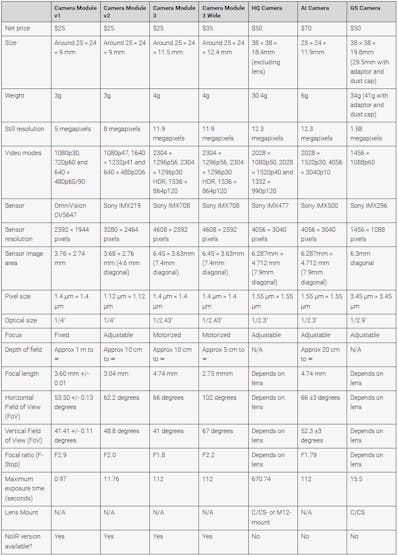
Raspberry Pi Camera Overview
Before considering which Zynq-UltraScale+ reference design to use, we need to select one of the Raspberry Pi camera modules for our application.
The following cameras are available from Raspberry Pi.
 : Raspberry Pi)
Raspberry Pi also has variations of their camera modules for:
- without IR filter : Camera V2 NoIR, Camera V3 NoIR
- wider field of fiew : Camera V3 Wide
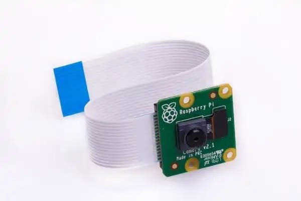
For this project, we will select the Camera V2 module for the simple reason that it is the one supported by the reference designs we are considering:
 : Raspberry Pi)
We will look at how to add support for the other camera modules in the next project in this series.
KV260 Design Overview
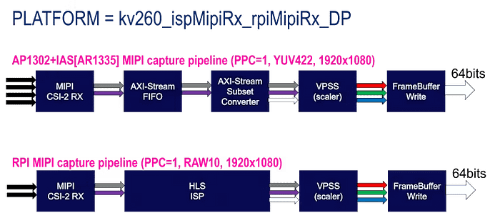
The first Zynq-UltraScale+ reference design that was made available for Raspberry Pi cameras was done specifically for the KV260 as a Vitis platform:
- kv260_ispMipiRx_rpiMipiRx_DP
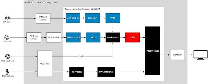
This platform is used by the NLP-SmartVision application, so I would refer to the documentation for that app for more details:
 : AMD)
One detail that I want to highlight is how the capture pipeline for the Raspberry Pi camera is implemented.
This Vitis platform actually contained two MIPI capture pipelines, as shown below:
 : AlbertaBeef)
For the Raspberry Pi camera’s capture pipline (rpiMipiRx), we can see that the Image Signal Processing (ISP) pipeline is implemented in HLS, and is supported by a linux kernel driver.
As part of this design’s legacy, we can now find the linux driver for the IMX219 sensor in AMD’s linux kernel repository:
Opsero Raspberry Pi Camera FMC
Jeff Johnson (Opsero) also created several Zynq-UltraScale+ reference designs for Raspberry Pi cameras, supporting several FMC carriers:
 : Opsero)
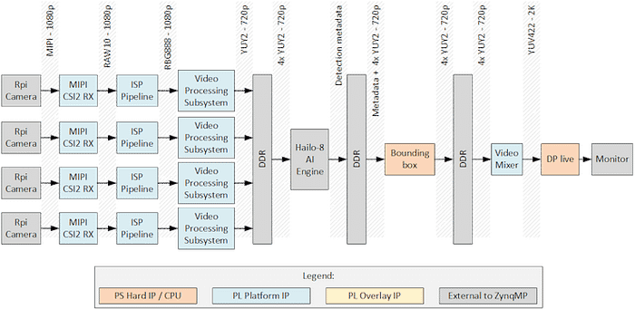 : Opsero)
I have chosen to use Jeff’s UltraZed-EV reference design as my starting point for this series for several reasons:
- excellent reference designs
- excellent documentation
- the UltraZed-EV is one of our development boards
- includes support for video encoding/decoding (VCU)
- includes support for Hailo-8
The next sections will provide a deep dive into the capture pipelines and display pipeline.
Building the Design
There is nothing I need to add to this topic, since Jeff has done an excellent job in describing how to rebuild his reference design:
Once done, you will have an SD card image, which you can program to a micro-SD card.
Setting up the Hardware
The following two images illustrate the hardware setup with the required RPI Camera FMC and Raspberry Pi V2 camera modules. The first (optional) setup also includes the additional M.2 Stack FMC + Hailo-8 option.
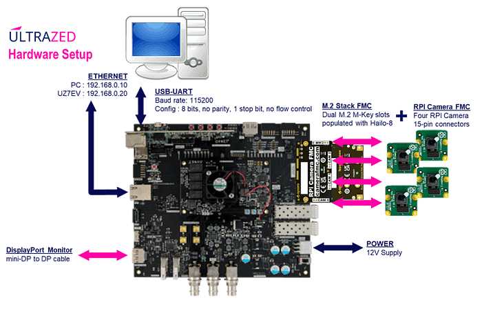 : AlbertaBeef)
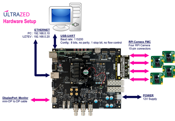 : AlbertaBeef)
I arranged the four (4) Raspberry Pi V2 camera modules as shown in the following images:
: AlbertaBeef)I quickly gathered random objects to create the following scene:
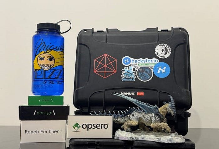 : AlbertaBeef)
Executing the Design
After booting the SD image, running the demos is as simple as running either of the following two scripts:
- displaycams.sh : quad-camera video passthrough
- hailodemo.sh : quad-camera yolov5 demonstration with Hailo-8
The passthrough demo can be launched as follows:
displaycams.sh
The displaycams.sh script performs the following:
- set the resolution of the monitor to 1920x1080 with the “modetest” utility
- initialize the capture pipeline to output 960x540 YUYV with the “v4l2-ctl” & “media-ctl” utilities
- launch the four passthrough pipelines with “gstreamer”
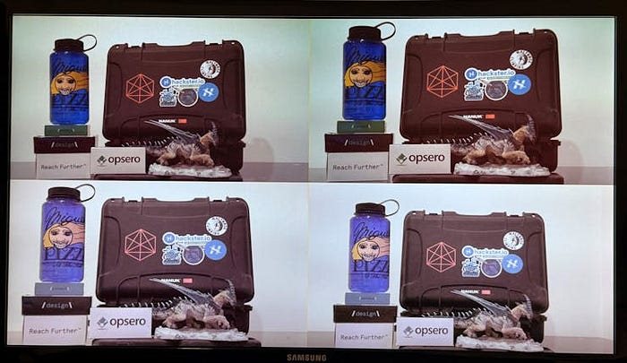 : AlbertaBeef)
CHALLENGE 1 : Can you guess why the bottom two captured video streams and different than the top two captured video streams ?
The Hailo-8 demo can be launched as follows:
hailodemo.sh
The hailodemo.sh script performs the following:
- set the monitor to its maximum supported resolution with the “modetest” utility
- initialize the capture pipeline to output 1280x720 YUYV with the “v4l2-ctl” & “media-ctl” utilities
- launch the four detection pipelines with “gstreamer”
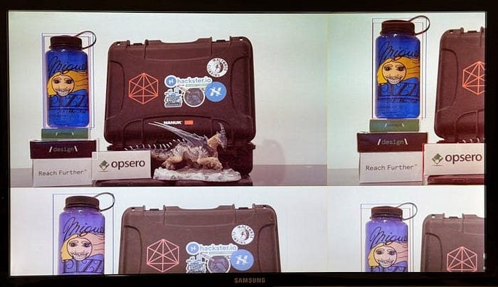 : AlbertaBeef)
CHALLENGE 2 : Can you guess why I was not able to see the entire content ?
A lot is going on behind the scenes when these scripts are launched. The following sections will give a brief overview of the capture and display pipelines, and how these are accessed in Linux.
Linux Capture Pipelines 101
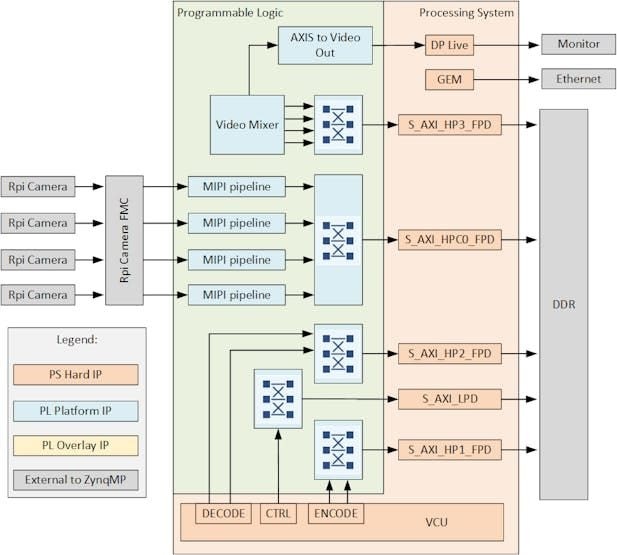
This design has four capture pipelines, each with the following architecture implemented in the programmable logic (PL):
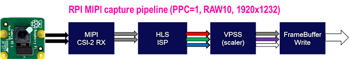 : AlbertaBeef)
Each MIPI capture pipeline has the following implementation details:
- MIPI CSI-2 RX input : 2 lanes, 456Mbps line rate, RAW10 format
- Pixel Per Clock (PPC) : 1
- Max Resolution : 1920x1232
In Linux, these capture pipelines are made accessible via the Video for Linux v2 (V4L2) framework.
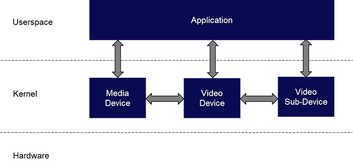 : AlbertaBeef)
Drivers are implemented in the kernel space for the following devices:
- media : /dev/media*
- video : /dev/video*
- sub-dev : /dev/v4l2-subdev*
In order to understand how these kernel driver map to our capture pipeline, we can use the V4L2 based utilities.
We will start by installing a few missing packages:
dnf install v4l-utils
dnf install media-ctl
dnf install yavta
dnf install graphviz
We can start by querying the V4L2 devices on our system:
root@uzev-hailo-2024-1:~# v4l2-ctl --list-devices

Xilinx Video Composite Device (platform:vcap_mipi_0_v_proc):
        /dev/media0

vcap_mipi_0_v_proc output 0 (platform:vcap_mipi_0_v_proc:0):
        /dev/video0

Xilinx Video Composite Device (platform:vcap_mipi_1_v_proc):
        /dev/media1

vcap_mipi_1_v_proc output 0 (platform:vcap_mipi_1_v_proc:0):
        /dev/video1

Xilinx Video Composite Device (platform:vcap_mipi_2_v_proc):
        /dev/media2

vcap_mipi_2_v_proc output 0 (platform:vcap_mipi_2_v_proc:0):
        /dev/video2

Xilinx Video Composite Device (platform:vcap_mipi_3_v_proc):
        /dev/media3

vcap_mipi_3_v_proc output 0 (platform:vcap_mipi_3_v_proc:0):
        /dev/video3
We can see that each of the four capture pipelines has a Media device (/dev/media*) and Video device (/dev/video*) associated with it.
We can further query the capture pipelines as follows:
media-ctl --print-dot -d /dev/media0 > dev_media_0_graph.dot
media-ctl --print-dot -d /dev/media1 > dev_media_1_graph.dot
media-ctl --print-dot -d /dev/media2 > dev_media_2_graph.dot
media-ctl --print-dot -d /dev/media3 > dev_media_3_graph.dot

dot -Tpng dev_media_0_graph.dot > dev_media_0_graph.png
dot -Tpng dev_media_1_graph.dot > dev_media_1_graph.png
dot -Tpng dev_media_2_graph.dot > dev_media_2_graph.png
dot -Tpng dev_media_3_graph.dot > dev_media_3_graph.png
This will create a visual representation of the capture pipelines:
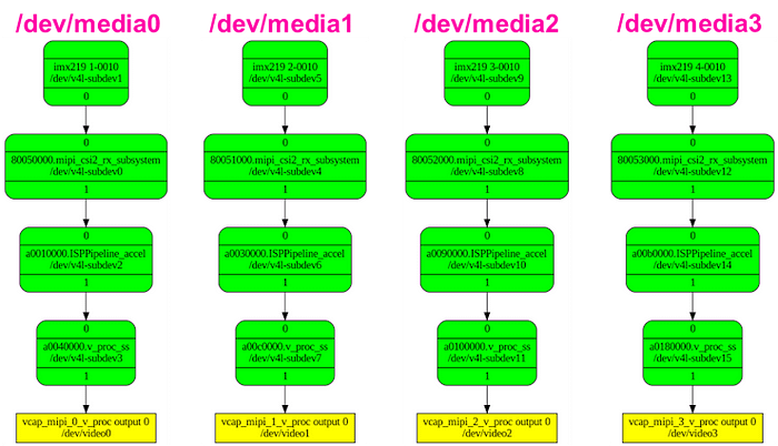 : AlbertaBeef)
We can see that each of the four capture pipelines has a Media device (/dev/media*), a Video device (/dev/video*), as well as four V4L Sub-Devices (/dev/v4l-subdev*) associated with it.
These map to the actual hardware as follows:
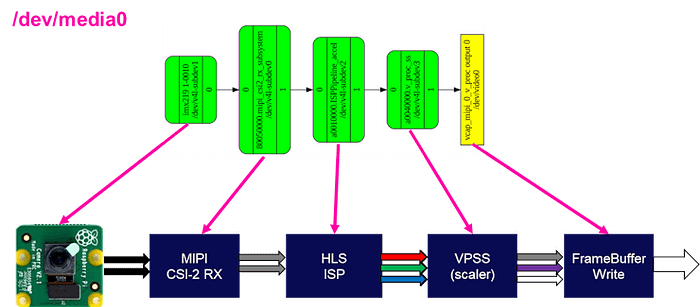 : AlbertaBeef)
We can use another utility, “yavta” to interact with these capture pipelines.
We start by calling “init_cams.sh”, which will configure the V4L2 capture pipelines (to the 1920x1080 resolution, and YUYV format).
root@uzev-hailo-2024-1:~# init_cams.sh
-------------------------------------------------
Capture pipeline init: RPi cam -> Scaler -> DDR
-------------------------------------------------
Configuring all video capture pipelines to:
- RPi Camera output    : 1920 x 1080
- Scaler (VPSS) output : 1920 x 1080 YUY2
Video Mixer found here:
- a0000000.v_mix
Detected and configured the following cameras on RPi Camera FMC:
- CAM0: /dev/media0 = /dev/video0
- CAM1: /dev/media1 = /dev/video1
- CAM2: /dev/media2 = /dev/video2
- CAM3: /dev/media3 = /dev/video3

root@uzev-hailo-2024-1:~#
Here are the details for the first capture pipeline:
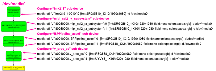 : AlbertaBeef)
Next, let’s capture one (raw) image from each capture pipeline (outputs to frame-000000.bin), then convert it to a viewable format with “ffmpeg”.
yavta-F /dev/video0 -n 1 -c1 -s 1920x1080 -f YUYV
ffmpeg-f rawvideo-s 1920x1080 -pix_fmtyuyv422 -iframe-000000.bin cam0.png
This will capture the following four images:
 : AlbertaBeef)
 : AlbertaBeef)
 : AlbertaBeef)
 : AlbertaBeef)
CHALLENGE 3 : Can the Capture Pipelines be configured for RGB output (versus YUYV output) ? If yes, how ?
Linux Display Pipelines 101
This design implements a sophisticated display pipeline.
By default, the Zynq-UltraScale+ provides a DisplayPort controller, with two layers:
- graphics : RGB layer with alpha (BGRA)
- video : real-time video layer supporting many formats (BGR, YUV, etc…)
Since the reference design has multiple video sources, we want more video layers, which is why Jeff included the Video Mixer. This core adds the following layers:
- graphics : RGB layer with alpha (BGRA)
- video : four (4) layers with YUYV format
In Linux, this display pipeline is made accessible via DRM (Direct Rendering Manager) and KMS (Kernel Mode Setting).
We can query the DRM implementation for our design with the “modetest” command:
root@uzev-hailo-2024-1:~# modetest -M xlnx
...
This generates a very long (at first, incomprehensible) description of our display pipeline.
We can summarize it as follows:
- Encoders : 59 (type TMDS)
- Connectors : 60 (name DP-1, status connected)
- CRTCs : 46 & 58
- Planes : 34, 36, 38, 40 (format YUYV), 42 (format AR24), 44 (format NV16), 54, 56
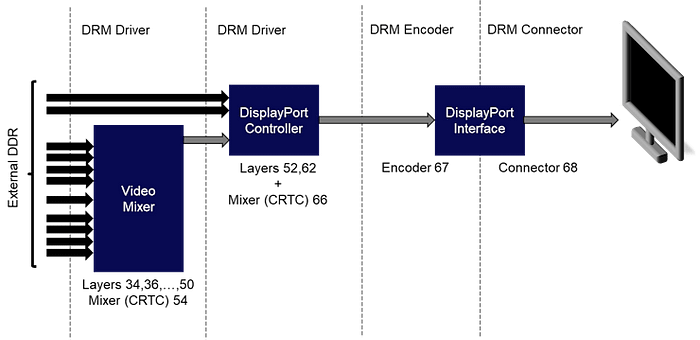
We can visualize this with the following representation:
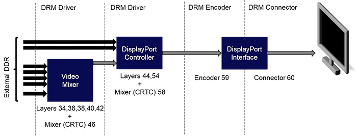 : AlbertaBeef)
The DRM framework has abstracted the hardware using the following representation:
- DRM driver : video layers & mixers, called CRTC in DRM framework
- DRM encoder : represents the interface to the monitor (ie. TMDS)
- DRM connector : represents for monitor
Another view of the DRM framework for our design, with an emphasis on the video layers, can be represented as shown below:
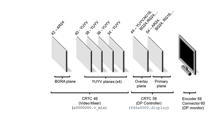 : AlbertaBeef)
We can imagine each layer being a transparent glass. When inactive, it will let the content from the previous (left) layers pass to the next layers. If it is active (or a portion of it is active, via alpha blending or render rectangles), it will pass its own content to the next (right) layers. The following examples will illustrate this.
We can use the “modetest” utility to interact with the display pipeline:
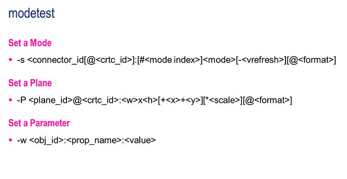 : AlbertaBeef)
Theoretically, we can use modetest with the DP Controller (CRTC 58). However, I have not been able to achieve this as shown below:
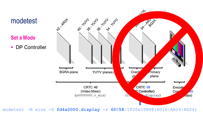 : AlbertaBeef)
This does work with a DP only design, so there is something that is missing in my comprehension of this complex display pipeline.
I will concentrate on the Video Mixer (CRTC 46) for the rest of this section.
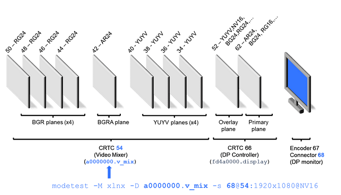
We can start by configuring the monitor to a specific resolution, as shown below:
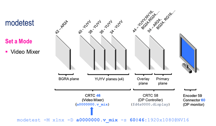 : AlbertaBeef)
The monitor will become blue, which is the default background color for the Video Mixer.
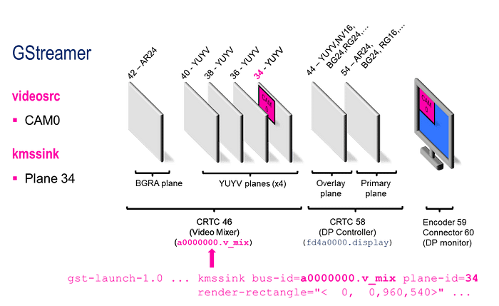
We can also start generating video content, as shown below, for the first YUYV layer (layer 34) of the video mixer (CRTC 46):
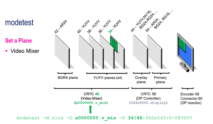 : AlbertaBeef)
This will display a diagonal bar pattern on the top left quadrant of the monitor.
We can do the equivalent for fourth YUYV layer (layer 40) of the video mixer (CRTC 46):
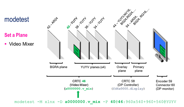 : AlbertaBeef)
We can also generate content to the display pipeline using GStreamer, as the demo scipts have done previously.
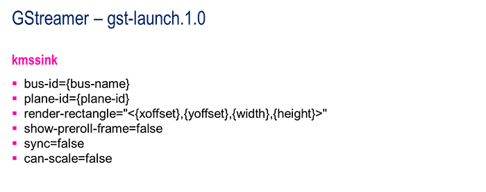 : AlbertaBeef)
The following diagrams illustrate how video was displayed by Gstreamer using the DRM framework:
 : AlbertaBeef)
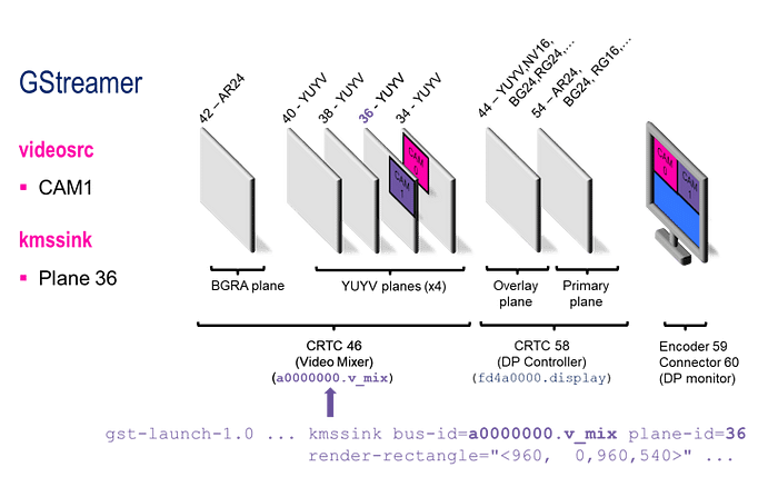 : AlbertaBeef)
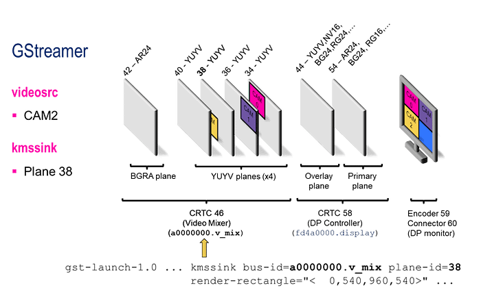 : AlbertaBeef)
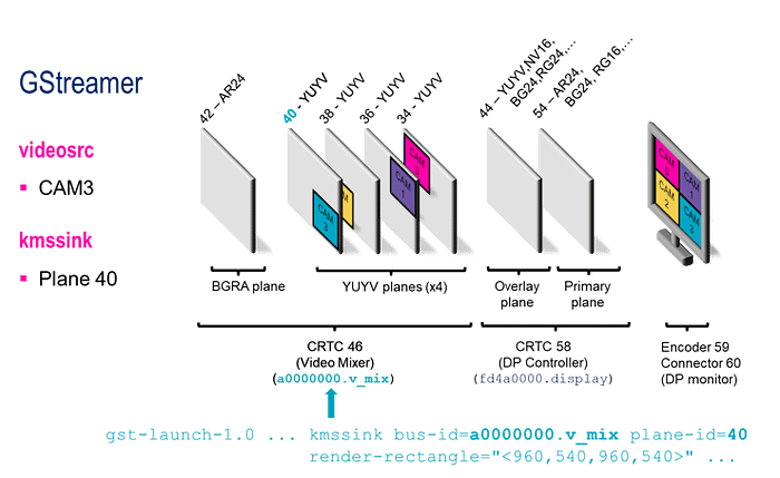 : AlbertaBeef)
CHALLENGE 4 : Is it possible to display RGB content in our Display Pipeline ? If yes, how ?
Modifying the Design
Jeff has even taken the time to document how to modify the reference design:
I will take the bait, and attempt to modify his design. I have chosen the following use case as an example of what users may want to modify:
- add support for BGR color format
The MIPI capture pipelines already support this color format, so there is nothing to do there. Recall that the display pipeline’s video mixer has one (1) BGRA layer for graphics, and four (4) YUYV overlays for real-time video.
Start by opening the Vivado project, located in the following directory:
zynqmp-hailo-ai/Vivado/uzev/uzev.xpr
vivado uzev.xpr &
NOTE : You may want to make a copy of the original design first, and/or work with a renamed copy of the original design.
Double click on the “rpi_i (rpi.bd)” IP Integrator block design, and navigate to the display_pipeline sub-system.
First, modify the Video Mixer to add four (4) additional layers for BGR format:
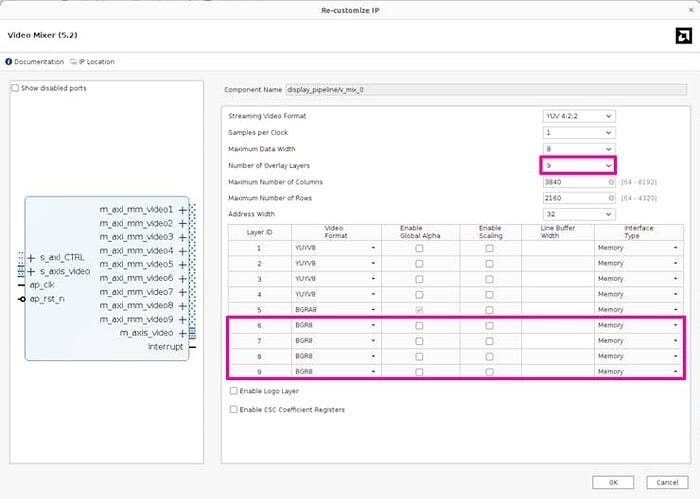 : AlbertaBeef)
Next, add four (4) additional slave interfaces to the AXI interconnect:
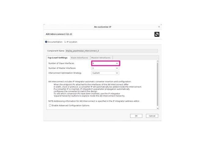 : AlbertaBeef)
Finally, make the connections to the new ports, as shown below:
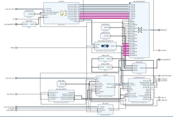 : AlbertaBeef)
Click on “Generate the Bitstream”, and wait for the build to complete.
These modifications have minimal impact on the resource utilization for the design, as shown in the following figures:
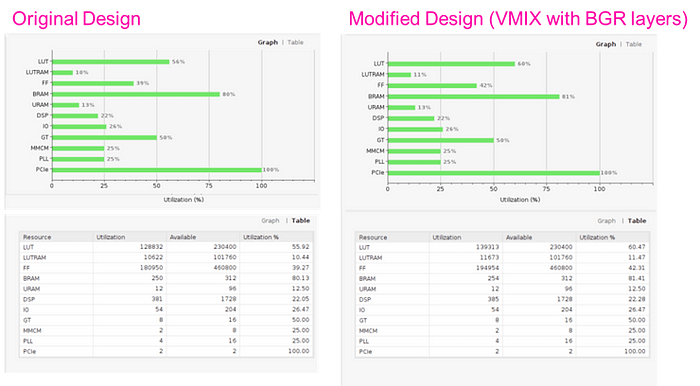 : AlbertaBeef)
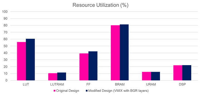 : AlbertaBeef)
Next, re-generate the XSA archive in the Tcl Console with the following command:
write_hw_platform -fixed -include_bit uzev.xsa
Next, we want to import these hardware changes to our petalinux project, located in the following directory:
zynqmp-hailo-ai/Petalinux/uzev
petalinux-config --silentconfig --get-hw-description=../../Vivado/uzev/uzev.xsa
Normally, we would need to update our device tree content, but in this case, the automatically generated content for the Video Mixer is correct, so no further modifications are needed.
Re-build the petalinux project, re-generate the SD image, and boot the new design on the UltraZed-EV board.
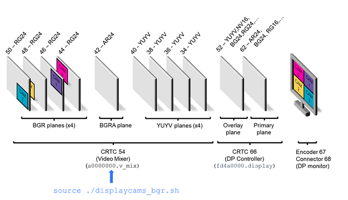
It is important to understand that we have now changed our display pipeline to the following:
 : AlbertaBeef)
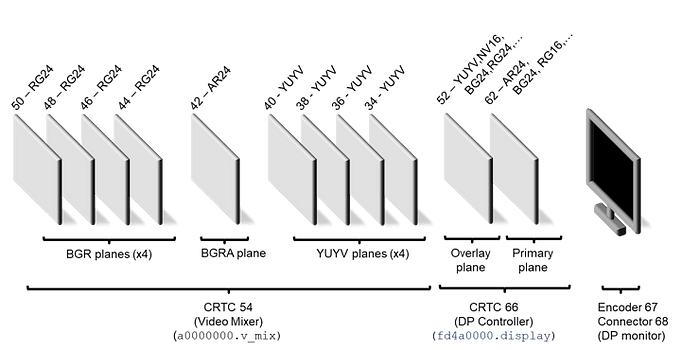 : AlbertaBeef)
Notice that the IDs for the components have changed:
- Video Mixer : CRTC 54
- DisplayPort Controller : CRTC 66, Layers 52, 62
- Encoder : 67
- Connector : 68
This needs to be reflected in the following scripts:
- init_cams.sh
- displaycams.sh
- hailodemo.sh
Specifically for the “displaycams.sh” script:
/usr/bin/displaycams.sh
We need to change the connector and CRTC IDs for the modetest command:
...
#-------------------------------------------------------------------------------
# Setup the display pipeline
#-------------------------------------------------------------------------------
# Initialize the display pipeline
#echo | modetest -M xlnx -D ${VMIX} -s 60@46:${DISP_RES}@NV16
echo | modetest -M xlnx -D ${VMIX} -s 68@54:${DISP_RES}@NV16
...
 : AlbertaBeef)
Let’s make a copy of this script, and rename it with the “_yuyv” suffix.
root@uzev-hailo-2024-1:~# cp /usr/bin/displaycams.sh ./displaycams_yuyv.sh
root@uzev-hailo-2024-1:~#
Let’s make a separate copy, and this time rename it with the “_bgr” suffix.
root@uzev-hailo-2024-1:~# cp /usr/bin/displaycams.sh ./displaycams_bgr.sh
root@uzev-hailo-2024-1:~#
In the “_bgr” version of the script, lets define the BGR format in the “format_dict” dictionnary, and change the planes (overlays) we are using for the kmssink output options:
...
# This dictionary associates GStreamer pixel formats with those used with media-ctl
declare -A format_dict
format_dict["NV12"]="VYYUYY8_1X24"
format_dict["YUY2"]="UYVY8_1X16"
format_dict["BGR"]="RBG888_1X24"
...
# Output format of the RPi camera pipelines (use a GStreamer pixel format from the dict above)
#OUT_FORMAT=YUY2
OUT_FORMAT=BGR
...
# Screen quadrants: TOP-LEFT, TOP-RIGHT, BOTTOM-LEFT, BOTTOM-RIGHT
quadrants_yuyv=(
        "plane-id=34 render-rectangle=\"<0,0,${OUT_RES_W},${OUT_RES_H}>\""
        "plane-id=36 render-rectangle=\"<${OUT_RES_W},0,${OUT_RES_W},${OUT_RES_H}>\""
        "plane-id=38 render-rectangle=\"<0,${OUT_RES_H},${OUT_RES_W},${OUT_RES_H}>\""
        "plane-id=40 render-rectangle=\"<${OUT_RES_W},${OUT_RES_H},${OUT_RES_W},${OUT_RES_H}>\""
)
quadrants_bgr=(
        "plane-id=44 render-rectangle=\"<0,0,${OUT_RES_W},${OUT_RES_H}>\""
        "plane-id=46 render-rectangle=\"<${OUT_RES_W},0,${OUT_RES_W},${OUT_RES_H}>\""
        "plane-id=48 render-rectangle=\"<0,${OUT_RES_H},${OUT_RES_W},${OUT_RES_H}>\""
        "plane-id=50 render-rectangle=\"<${OUT_RES_W},${OUT_RES_H},${OUT_RES_W},${OUT_RES_H}>\""
)
...
# For each connected camera, add pipeline to gstreamer command
for media in "${!media_to_video_mapping[@]}"; do
        # Append the specific command for the current iteration to the full command
        full_command+=" v4l2src device=${media_to_video_mapping[$media]} io-mode=mmap"
        #full_command+=" ! video/x-raw, width=${OUT_RES_W}, height=${OUT_RES_H}, format=YUY2, framerate=${FRM_RATE}/1"
        full_command+=" ! video/x-raw, width=${OUT_RES_W}, height=${OUT_RES_H}, format=BGR, framerate=${FRM_RATE}/1"
        full_command+=" ! kmssink bus-id=${VMIX} ${quadrants_bgr[$index]} show-preroll-frame=false sync=false can-scale=false"
        ((index++))
done
...
 : AlbertaBeef)
Summary
If your are looking to use Raspberry Pi cameras with a Zynq-UltraScale+ based design, I hope that you found this project helpful.
Are you currently using the Raspberry Pi cameras in your embedded projects ? If yes, which platform are you using ?
If you were able to answer the 4 challenge questions, please share your responses in the comments below …
Known Issues
The following issues are currently unresolved:
- Not able to control DP Controller Planes & CRTC (not critical)
Acknowledgements
I want to thank Jeff Johnson (Opsero) for his excellent reference design, as well as his fabulous portfolio of FMC hardware:
- [Opsero] RPI Camera FMC
- [Opsero] M.2 M-key Stack FMC
I also want to thank Gianluca Filippini (EBV) for his pioneering work with the Hailo-8 AI Accelerator module, and bringing this marvel to my attention. His feedback, guidance, and insight have been invaluable.
- [Hailo] Hailo-8 AI Acceleration module
Version History
- 2024/12/23 — Initial Version
References
- [Raspberry Pi] RPI Camera Portfolio
- [AMD] Kria AI Vision Kit — NLP-SmartVision app
- [Opsero] RPI Camera FMC Reference Design
- [Ospero] RPI Camera FMC Reference Design — Building
- [Ospero] RPI Camera FMC Reference Design — Modifying
- [AMD/Xilinx] DRM KMS Driver
- [AMD/Xilinx] Video Mixer — Linux Driver
- [AMD/Xilinx] ZynqMP DisplayPort Controller — Linux Driver