In this project, I will modify the Opsero RPI Camera FMC design to support other cameras in the Raspberry Pi portfolio:
- Raspberry Pi Camera Module V2
- Raspberry Pi Camera Module V3
- Raspberry Pi HQ Camera
- Raspberry Pi AI Camera

In order to accomplish this, I will start by looking at the working reference implementations from Raspberry Pi, specifically on the RPI 5 kit.
With this understanding, I will then proceed to update the design as follows:
- Adapting the ISPPipeline core to each camera
- Modifying the Vivado project for each capture pipeline
- Modifying the Petalinux project to add support for each sensor’s driver
- Boot the modified design to validate the detection of new sensors
- Write applications to test each of our newly supported cameras
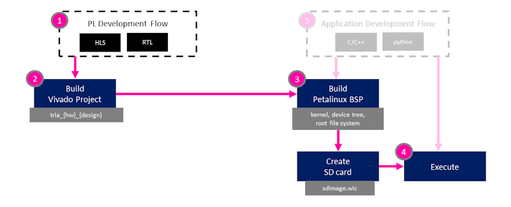
I have created a visual representation of the roadmap for this project.
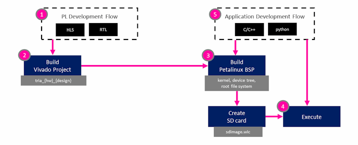
Raspberry Pi Camera working References
In order to understand the impact that the modifications will have on the current design, we need to understand the specifications of the cameras we intend to support:
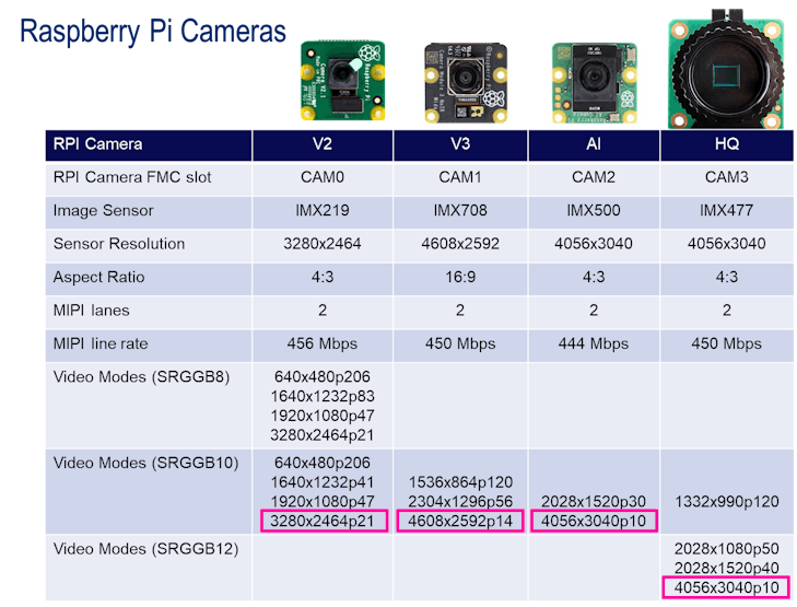
The mapping of each of the four (4) cameras to the RPI Camera FMC slot is a personal choice. The order of the first three is chronological, where-as the HQ camera is mapped to the last slot to facilitate mounting of the larger form-factor.
If we want to support the largest resolutions, we will need to modify our hardware design as follows:
- Increase current size of maximum resolution from to 1920x1232 to each camera’s maximum resolution
- Change current RAW10 format for CAM3 to RAW12 to support higher resolutions
- Change current MIPI line rate of 420 Mbps (not certain where this value comes from) to the required 456|450|444|450 Mbps for each MIPI interface
We will need to have separate instances of the ISPPipeline, tailored to each camera, in order to support different formats (RAW10 versus RAW12) and different resolutions.
We will also want to add the device drivers for each of the Raspberry Pi cameras.
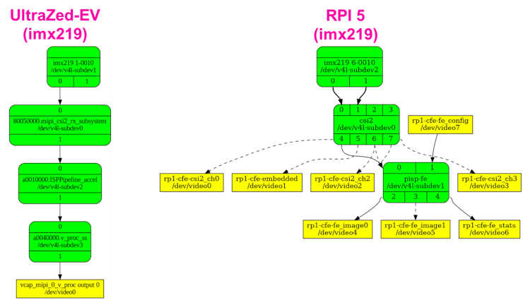
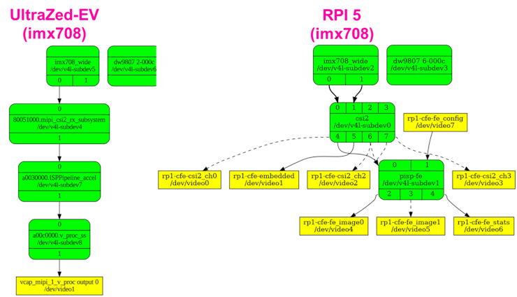
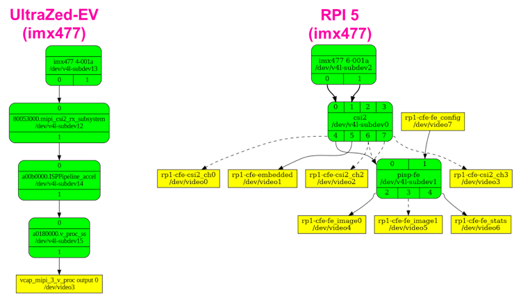
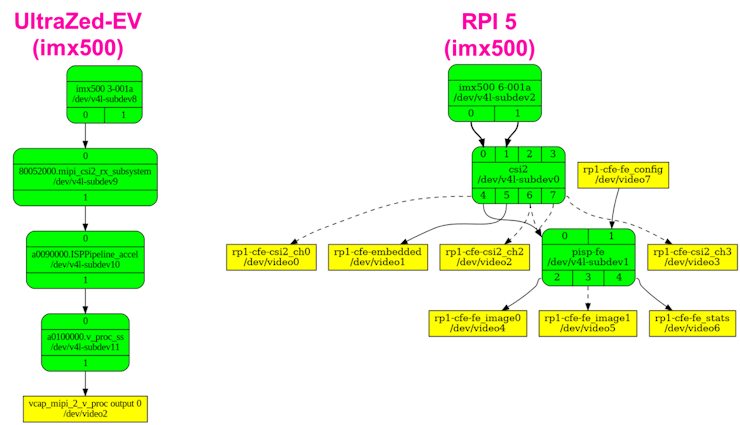
If we compare the media nodes for each camera, we can observe the following:
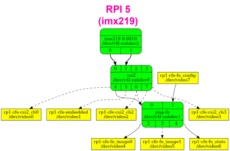
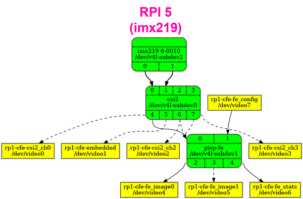
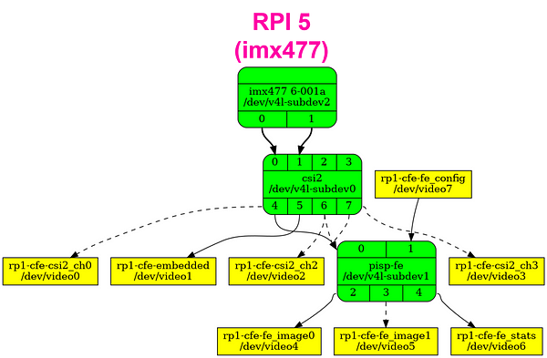
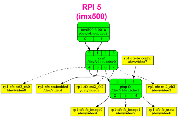
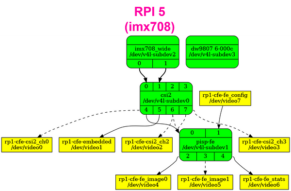
If we compare with the media node from our existing project, one thing should stand out:

The IMX* drivers have two output nodes, instead of one. Diving into the code, this second output node is declared and used for meta-data. Although I cannot be certain what this is used for in the case of the IMX219, IMX708, and IMX477 sensors, it definitely makes sense for the IMX500 sensor, which has built-in AI functionality. This meta-data output is probably used for the classification results and/or bounding boxes generated by the AI engine.
We will need to figure out how to access this output node, which is most probably implemented as a virtual channel on the MIPI interface.
- Add AXI-Stream switch to split video & meta-data from MIPI stream
Adapting the ISPPipeline to each camera
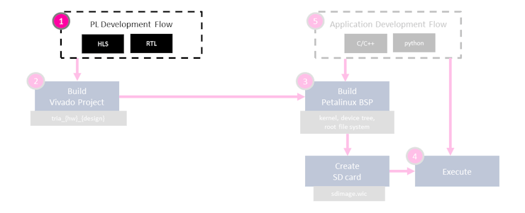
Adapting the ISPPipeline for each image sensor would require having separate instances of the core. From a hardware perspective, this would involve copying and renaming the top level source file and defining cores with different names.
However, I an uncertain how the ISPPipeline driver would support these “multiple” variations of the IP core. For this reason, I decided to choose a common configuration for all image sensors.
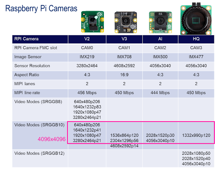
The first configuration I tried is 10 bit mode (RAW10) with a maximum resolution of 4096x4096:
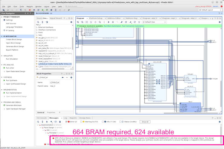
This ultimately resulted in a lack of PL resources, as shown below:
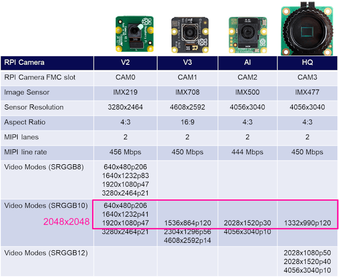
My first reaction was to scale down my requirements to a maximum resolution of 2048x2048:
Then I realized that the design was dominated by BRAM usage, and that there was a URAM option that was not being used in the ISPPipeline.
The following figures illustrates the resource utilization with and without the ISPPipeline’s URAM option, and with different maximum resolutions (2048x2048 versus 4096x4096):
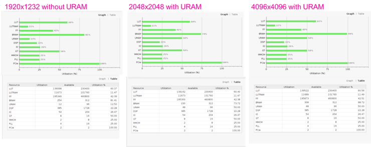
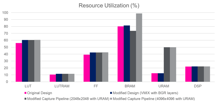
Note that using URAM option reduces the BRAM utlization but increases the URAM utilization. The good news is that the URAM utilization does not change between 2048x2048 and 4096x4096 implementations. Most importantly, using the URAM option allows enough resources for the 4096x4096 implementation.
For this project, I decided to stay with the 2048x2048 version of the capture pipelines, with the URAM option enabled.
I started by copying the Vivado/ip directory to a new Vivado/ip_4k:
cd Vivado
cp -r ip ip_2048x2048
I then navigated to the ip_2048x2048 directory, and edited the config file:
cd ip_2048x2048
gedit isppipeline/include/xf_config_params.h
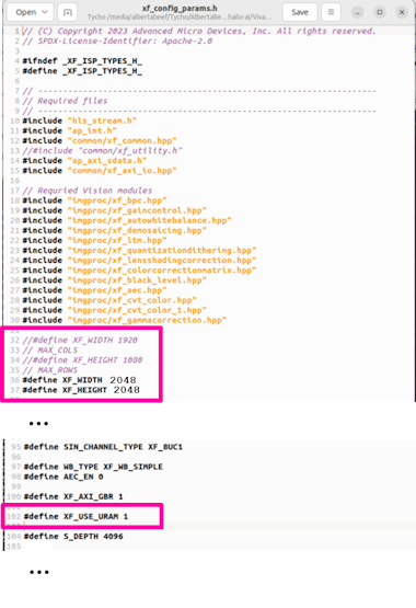
Then I re-built the ISPPipeline core in the “ip_2048x2048” directory:
make clean TARGET=uzev
make ip TARGET=uzev
Modifying the Vivado project
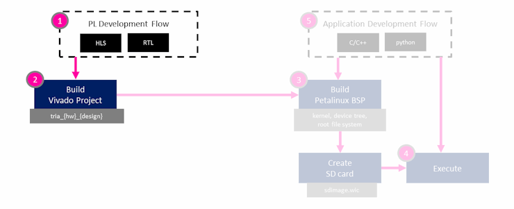
With the new version of the ISPPipeline core in the “ip_2048x2048” directory, we can update the Vivado project.
We start by updating the IP repository path from “../Vivado/ip/build/ultrazed_7ev_cc” to “../Vivado/ip_2048x2048/build/ultrazed_7ev_cc”, as shown below:
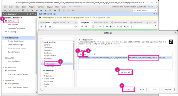
The Vivado project will detect the IP core change, and request to update the cores in the design:
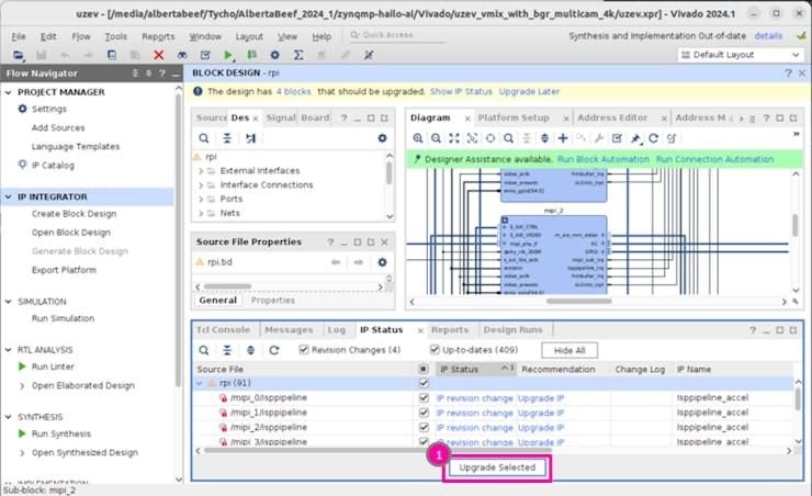
Next, we want the configure the MIPI capture pipelines for the new maximum resolution of 2048x2048.
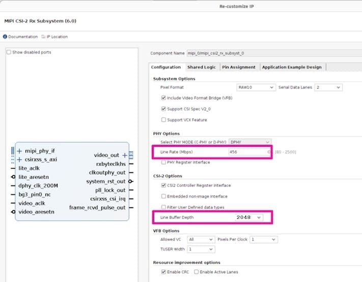
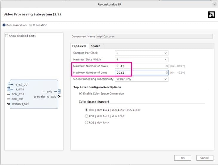
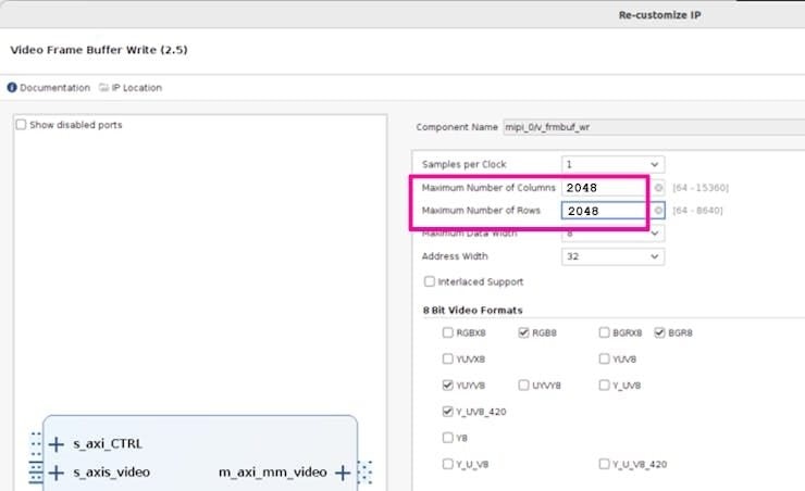
Click on “Generate the Bitstream”, and wait for the build to complete.
Next, re-generate the XSA archive in the Tcl Console with the following command:
write_hw_platform -fixed -include_bit uzev_multicam.xsa
Modifying the Petalinux project
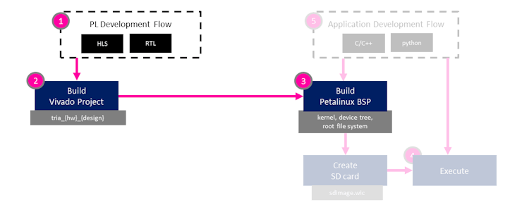
The first step to update our petalinux project is to import the modified hardware design. Assuming a copy of the original Vivado and Petalinux project were copied/renamed with the “_multi” suffix, this can be done as follows:
cd ../../Petalinux/uzev_multicam
petalinux-config --silentconfig --get-hw-description=../../Vivado/uzev_multicam/ezev_multicam.xsa
Modifying the petalinux project to support the new Raspberry Pi cameras will be done in several major steps:
- Patching the Kernel
- Updating the Device Tree
The following sections will dive into these steps in more detail.
Modifying the Petalinux project — Patching the Kernel
The first major step we need to accomplish is to incorporate the linux device drivers for each of our targeted cameras.
Since Petalinux 2024.1 uses Linux kernel 6.6.10, I will reference version 6.6.y of the Raspberry Pi Linux kernel repository:
We can clone a local copy for reference:
git clone https://github.com/raspberrypi/linux/tree/rpi-6.6.y
In the petalinux project, I need to modify the linux kernel. This will be done in the form of patches, which we will include in the yocto recipes.
I will use the “devtool” to create a local sandbox to modify the linux kernel source, and generate the kernel patches. The following is a quick overview of the commands that we will use to accomplish this:
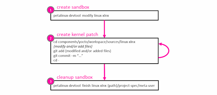
The kernel patches will be generated during the “petalinux-devtool finish linux-xlnx …” command. The descriptions provided during “git commit …” will become the name of the patches, prefixed with an 4 digit id.
For more detailed information on using devtool with petalinux, refer to UG1144:
- https://docs.amd.com/r/2024.1-English/ug1144-petalinux-tools-reference-guide/petalinux-devtool
- https://docs.amd.com/r/2024.1-English/ug1144-petalinux-tools-reference-guide/petalinux-devtool-Examples
We start by creating a local sandbox for the linux kernel source:
petalinux-devtool modify linux-xlnx
Then we can observe the differences between version 6.6.y of the Raspberry Pi “linux” repository, and our 6.6.10 version of the AMD/Xilinx “linux-xlnx” linux kernel repository:
meld components/yocto/workspace/sources/linux-xlnx ../../rpi-6.6.y &
The first modification we will make relates to the format definition for the meta-data (ie. second output port of the imx* drivers).
We want to add the MEDIA_BUS_FMT_SENSOR_DATA definition to the following source file:
include/uapi/linux/media-bus-format.h
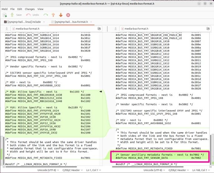
NOTE : It is important to preserve the AMD/Xilinx specific definitions
Every time a modification is made, and verified with a petalinux-build, we want to perform a git add/commit, which will create the patch file we will be reusing in our final design. For the example of “media-bus-format.h”, this would be done as follows:
cd components/yocto/workspace/sources/linux-xlnx
git add include/uapi/linux/media-bus-format.h
git commit -m "Add MEDIA_BUS_FMT_SENSOR_DATA format based on rpi-6.6.y source."
cd -
We will now progressively modify and/or add files in the linux kernel source to support the Raspberry Pi cameras.
For the RPI Cam V2, this involves:
- updating drivers/media/i2c/imx219.c
(which adds a new binning implementation, and adds the second output port for meta-data)
For the RPI Cam V3, this involves:
- adding drivers/media/i2c/imx708.c
- modifying drivers/media/i2c/the dw9807_vcm.c
(to add support for the dw9817 device)
For the RPI HQ Camera, this involves:
- adding drivers/media/i2c/imx477.c
For the RPI AI Camera, this involves:
- adding drivers/media/i2c/imx500.c
- adding drivers/spi/spi-rp2040-gpio-bridge.c
- modifying drivers/media/v4l2-core/v4l2-cci.c and include/v4l2-core/v4l2-cci.h
Once done with the modifications, we can finish our sandbox with the following command, which will generate our kernel patches:
petalinux-devtool finish linux-xlnx {full path to}/project-spec/meta-user
At the end of this process, I ended up with the following eight (8) kernel patches:
0001-Add-MEDIA_BUS_FMT_SENSOR_DATA-format-based-on-rpi-6.6.y.patch
0002-media-i2c-Update-imx219-driver-based-on-rpi-6.6.y.patch
0003-media-i2c-Add-imx708-driver-based-on-rpi-6.6.y.patch
0004-media-i2c-Update-dw9807-vcm-driver-based-on-rpi-6.6.y.patch
0005-media-i2c-Add-imx477-driver-based-on-rpi-6.6.y.patch
0006-media-i2c-Add-imx500-driver-based-on-rpi-6.6.y.patch
0007-spi-Add-spi-rp2040-gpio-bridge-driver-based-on-rpi-6.6.y.patch
0008-media-v4l2-core-Update-v4l2-cci-driver-based-on-rpi-6.6.y.patch
The kernel config file needs to be updated to include the modified/new drivers in the kernel:
project-spec/meta-user/recipes-kernel/linux/linux-xlnx/bsp.cfg
# RPI AI Camera
CONFIG_VIDEO_IMX500=y
CONFIG_SPI_RP2040_GPIO_BRIDGE=y
CONFIG_V4L2_CCI=y
CONFIG_V4L2_CCI_I2C=y

# RPI HQ Camera
CONFIG_VIDEO_IMX477=y
# RPI Camera V3
CONFIG_VIDEO_IMX708=y
CONFIG_VIDEO_DW9807_VCM=y
# RPI Camera V2
CONFIG_VIDEO_IMX219=y
...
Modifying the Petalinux project — Updating the Device Tree
The second major step we need to accomplish is to update the device tree content for each of our targeted cameras.
Once again, I will reference version 6.6.y of the Raspberry Pi Linux kernel repository:
RPI camera V2 : device tree content
For the imx219 sensor, I reference the following device tree content:
- https://github.com/raspberrypi/linux/blob/rpi-6.6.y/arch/arm/boot/dts/overlays/imx219-overlay.dts
- https://github.com/raspberrypi/linux/blob/rpi-6.6.y/arch/arm/boot/dts/overlays/imx219.dtsi
Here is the working device tree content for the V2 camera (imx219 sensor):
project-spec/meta-user/recipes-bsp/device-tree/files/system-user.dtsi
...
        imx219_clk: imx219_clk {
                #clock-cells = <0x0>;
                clock-frequency = <24000000>;
                compatible = "fixed-clock";
        };
	imx219_vana: fixedregulator@3 {
		compatible = "regulator-fixed";
		regulator-name = "imx219_vana";
		regulator-min-microvolt = <2800000>;
		regulator-max-microvolt = <2800000>;
		enable-active-high;
	};
	imx219_vdig: fixedregulator@4 {
		compatible = "regulator-fixed";
		regulator-name = "imx219_vdig";
		regulator-min-microvolt = <1800000>;
		regulator-max-microvolt = <1800000>;
	};
	imx219_vddl: fixedregulator@5 {
		compatible = "regulator-fixed";
		regulator-name = "imx219_vddl";
		regulator-min-microvolt = <1200000>;
		regulator-max-microvolt = <1200000>;
	};
...
&mipi_0_axi_iic_0 {
	imx219_cam0: sensor@10 {
		compatible = "sony,imx219";
		reg = <0x10>;

		clocks = <&imx219_clk>;
		clock-names = "xclk";

		VANA-supply = <&imx219_vana>;   /* 2.8v */
		VDIG-supply = <&imx219_vdig>;   /* 1.8v */
		VDDL-supply = <&imx219_vddl>;   /* 1.2v */
		rotation = <180>;
		orientation = <2>;

		port {
		     imx219_cam0_0: endpoint {
		        clock-lanes = <0>;
			data-lanes = <1 2>;
			clock-noncontinuous;
			link-frequencies = /bits/ 64 <456000000>;

			remote-endpoint = <&mipi_csi_inmipi_0_mipi_csi2_rx_subsyst_0>;
			};
		};
	};
};
...
&mipi_0_isppipeline {
	reset-gpios = <&gpio 86 1>;
	xlnx,max-height = /bits/ 16 <2048>;
	xlnx,max-width = /bits/ 16 <2048>;
	xlnx,rgain = /bits/ 16 <128>;
	xlnx,bgain = /bits/ 16 <210>;
	xlnx,pawb = /bits/ 16 <350>;
	xlnx,mode-reg = <1>;
};
...
And the resulting media node, compared to the reference RPI5 implementation:
RPI camera V3 : device tree content
For the imx708 sensor, I reference the following device tree content:
- https://github.com/raspberrypi/linux/blob/rpi-6.6.y/arch/arm/boot/dts/overlays/imx708-overlay.dts
- https://github.com/raspberrypi/linux/blob/rpi-6.6.y/arch/arm/boot/dts/overlays/imx708.dtsi
Here is the working device tree content for the V3 camera (imx708 sensor):
project-spec/meta-user/recipes-bsp/device-tree/files/system-user.dtsi
...
       imx708_clk: imx708_clk {
                #clock-cells = <0x0>;
                clock-frequency = <24000000>;
                compatible = "fixed-clock";
        };
	imx708_vana1: fixedregulator@3 {
		compatible = "regulator-fixed";
		regulator-name = "imx708_vana1";
		regulator-min-microvolt = <2800000>;
		regulator-max-microvolt = <2800000>;
		enable-active-high;
	};
	imx708_vana2: fixedregulator@3 {
		compatible = "regulator-fixed";
		regulator-name = "imx708_vana2";
		regulator-min-microvolt = <1800000>;
		regulator-max-microvolt = <1800000>;
		enable-active-high;
	};
	imx708_vdig: fixedregulator@4 {
		compatible = "regulator-fixed";
		regulator-name = "imx708_vdig";
		regulator-min-microvolt = <1100000>;
		regulator-max-microvolt = <1100000>;
	};
	imx708_vddl: fixedregulator@5 {
		compatible = "regulator-fixed";
		regulator-name = "imx708_vddl";
		regulator-min-microvolt = <1800000>;
		regulator-max-microvolt = <1800000>;
	};
...
&mipi_1_axi_iic_0 {
	imx708_cam1: sensor@10 {
		compatible = "sony,imx708";
		reg = <0x1a>;
		status = "okay";

		clocks = <&imx708_clk>;
		clock-names = "inclk";

		vana1-supply = <&imx708_vana1>;   /* 2.8v */
		vana2-supply = <&imx708_vana2>;   /* 1.8v */
		vdig-supply = <&imx708_vdig>;   /* 1.1v */
		vddl-supply = <&imx708_vddl>;   /* 1.8v */
		rotation = <180>;
		orientation = <2>;
		lens-focus = <&vcm_node>;

		port {
		     imx708_cam1_0: endpoint {
		        clock-lanes = <0>;
			data-lanes = <1 2>;
			clock-noncontinuous;
			link-frequencies = /bits/ 64 <450000000>;

			remote-endpoint = <&mipi_csi_inmipi_1_mipi_csi2_rx_subsyst_0>;
			};
		};
	};
	vcm_node: dw9817@c {
		compatible = "dongwoon,dw9817-vcm";
		reg = <0x0c>;
		status = "okay";

		VDD-supply = <&imx708_vana1>; /* 2.8v */
	};
};
...
&mipi_1_isppipeline {
	reset-gpios = <&gpio 94 1>;
	xlnx,max-height = /bits/ 16 <2048>;
	xlnx,max-width = /bits/ 16 <2048>;
	xlnx,rgain = /bits/ 16 <128>;
	xlnx,bgain = /bits/ 16 <210>;
	xlnx,pawb = /bits/ 16 <350>;
	xlnx,mode-reg = <1>;
};
...
And the resulting media node, compared to the reference RPI5 implementation:
RPI HQ camera : device tree content
For the imx477 sensor, I reference the following device tree content:
- https://github.com/raspberrypi/linux/blob/rpi-6.6.y/arch/arm/boot/dts/overlays/imx477_378-overlay.dtsi
- https://github.com/raspberrypi/linux/blob/rpi-6.6.y/arch/arm/boot/dts/overlays/imx477_378.dtsi
Here is the working device tree content for the HQ camera (imx477 sensor):
project-spec/meta-user/recipes-bsp/device-tree/files/system-user.dtsi
...
       imx477_clk: imx477_clk {
               #clock-cells = <0x0>;
               clock-frequency = <24000000>;
               compatible = "fixed-clock";
        };
	imx477_vana: fixedregulator@3 {
		compatible = "regulator-fixed";
		regulator-name = "imx477_vana";
		regulator-min-microvolt = <2800000>;
		regulator-max-microvolt = <2800000>;
		enable-active-high;
	};
	imx477_vdig: fixedregulator@4 {
		compatible = "regulator-fixed";
		regulator-name = "imx477_vdig";
		regulator-min-microvolt = <1050000>;
		regulator-max-microvolt = <1050000>;
	};
	imx477_vddl: fixedregulator@5 {
		compatible = "regulator-fixed";
		regulator-name = "imx477_vddl";
		regulator-min-microvolt = <1800000>;
		regulator-max-microvolt = <1800000>;
	};
...
&mipi_3_axi_iic_0 {
	imx477_cam3: sensor@1a {
		compatible = "sony,imx477";
		reg = <0x1a>;
		status = "okay";

		clocks = <&imx477_clk>;
		clock-names = "xclk";

		VANA-supply = <&imx477_vana>;   /* 2.8v */
		VDIG-supply = <&imx477_vdig>;   /* 1.05v */
		VDDL-supply = <&imx477_vddl>;   /* 1.8v */

		rotation = <180>;
		orientation = <2>;
		port {
		     imx477_cam3_0: endpoint {
		        clock-lanes = <0>;
			data-lanes = <1 2>;
			clock-noncontinuous;
			link-frequencies = /bits/ 64 <450000000>;

			remote-endpoint = <&mipi_csi_inmipi_3_mipi_csi2_rx_subsyst_0>;
			};
		};
	};
};
...
&mipi_3_isppipeline {
	reset-gpios = <&gpio 110 1>;
	xlnx,max-height = /bits/ 16 <2048>;
	xlnx,max-width = /bits/ 16 <2048>;
	xlnx,rgain = /bits/ 16 <128>;
	xlnx,bgain = /bits/ 16 <210>;
	xlnx,pawb = /bits/ 16 <350>;
	xlnx,mode-reg = <1>;
};
...
And the resulting media node, compared to the reference RPI5 implementation:
RPI AI camera : device tree content
For the imx500 sensor, I reference the following device tree content:
- https://github.com/raspberrypi/linux/blob/rpi-6.6.y/arch/arm/boot/dts/overlays/imx500-overlay.dts
- https://github.com/raspberrypi/linux/blob/rpi-6.6.y/arch/arm/boot/dts/overlays/imx500-rpi5-overlay.dts
- https://github.com/raspberrypi/linux/blob/rpi-6.6.y/arch/arm/boot/dts/overlays/imx500.dtsi
- https://github.com/raspberrypi/linux/blob/rpi-6.6.y/arch/arm/boot/dts/overlays/rpi-rp2040-gpio-bridge.dtsi
Here is the device tree content for the AI camera (imx500 sensor):
project-spec/meta-user/recipes-bsp/device-tree/files/system-user.dtsi
...
        imx500_clk: imx500_clk {
                #clock-cells = <0x0>;
                clock-frequency = <24000000>;
                compatible = "fixed-clock";
        };
	imx500_vana: fixedregulator@3 {
		compatible = "regulator-fixed";
		regulator-name = "imx500_vana";
		regulator-min-microvolt = <2700000>;
		regulator-max-microvolt = <2700000>;
		enable-active-high;
	};
	imx500_vdig: fixedregulator@4 {
		compatible = "regulator-fixed";
		regulator-name = "imx500_vdig";
		regulator-min-microvolt = <840000>;
		regulator-max-microvolt = <840000>;
	};
	imx500_vif: fixedregulator@5 {
		compatible = "regulator-fixed";
		regulator-name = "imx500_vif";
		regulator-min-microvolt = <1800000>;
		regulator-max-microvolt = <1800000>;
	};

	clk_aicam: clk-aicam1 {
		compatible = "fixed-clock";
		#clock-cells = <0>;
		clock-frequency = <24000000>;
	};
	clk_aicam_gated: clk-aicam-gated1 {
		compatible = "gpio-gate-clock";
		clocks = <&clk_aicam>;
		#clock-cells = <0>;
		enable-gpios = <&spi_bridge 21 GPIO_ACTIVE_HIGH>;
	};
...
&mipi_2_axi_iic_0 {
	imx500_cam2: sensor@1a {
		compatible = "sony,imx500";
		reg = <0x1a>;
		status = "okay";

		//clocks = <&imx500_clk>;
		//clock-names = "inclk";
		clocks = <&clk_aicam_gated>;

		vana-supply = <&imx500_vana>;   /* 2.7v */
		vdig-supply = <&imx500_vdig>;   /* 0.84v */
		vif-supply = <&imx500_vif>;   /* 1.8v */

		rotation = <0>;
		orientation = <2>;
		led-gpios = <&spi_bridge 19 GPIO_ACTIVE_HIGH>;
		reset-gpios = <&spi_bridge 20 GPIO_ACTIVE_HIGH>;
		spi = <&spi_bridgedev0>;

		port {
		     imx500_cam2_0: endpoint {
		        clock-lanes = <0>;
			data-lanes = <1 2>;
			clock-noncontinuous;
			link-frequencies = /bits/ 64 <444000000>;
			remote-endpoint = <&mipi_csi_inmipi_2_mipi_csi2_rx_subsyst_0>;
			};
		};
	};
	spi_bridge: spi@40 {
		reg = <0x40>;
		compatible = "raspberrypi,rp2040-gpio-bridge";
		status = "okay";

		#address-cells = <1>;
		#size-cells = <0>;
power-supply = <&imx500_vana>; /* 2.7v */
		#gpio-cells = <2>;
		gpio-controller;

		fast_xfer_requires_i2c_lock = <1>;
		fast_xfer_recv_gpio_base = <11>;
		/*
		// TODO : connection to AXI_SPI ?
		fast_xfer-gpios = <&rp1_gpio 40 0>, // CD1_SDA (used as data)
				  <&rp1_gpio 48 0>; // CD1_IO1_MICDAT1 (clock)
		*/

		bypass-cache?;

		spi_bridgedev0: spidev@0{
			compatible = "sony,imx500";
			reg = <0>;	/* CE0 */
			#address-cells = <1>;
			#size-cells = <0>;
			spi-max-frequency = <35000000>;
		};
	};
};
...
&mipi_2_isppipeline {
	reset-gpios = <&gpio 102 1>;
	xlnx,max-height = /bits/ 16 <2048>;
	xlnx,max-width = /bits/ 16 <2048>;
	xlnx,rgain = /bits/ 16 <128>;
	xlnx,bgain = /bits/ 16 <210>;
	xlnx,pawb = /bits/ 16 <350>;
	xlnx,mode-reg = <1>;
};
...
And the resulting media node, compared to the reference RPI5 implementation:
The imx500 device tree content is much more complex that first appears … several few trial-and-error iterations were required to get I2C transactions working with the imx500.
For example, the imx500 is held in reset by the rp2040 device, so the definition for this gpio-bridge was essential to getting the imx500 up and running.
I suspect that much more is required to get this camera working, such as:
- Implementing the “fast_xfer-gpios” in the PL, and defining these in the device tree
- Providing the firmware for the rp2040 micro-controller (do we need to provide this ?)
The following reference provides some information:
Setting up the Hardware
The following two images illustrate the hardware setup with the required RPI Camera FMC and Raspberry Pi camera modules. The first (optional) setup also includes the additional M.2 Stack FMC + Hailo-8 option.
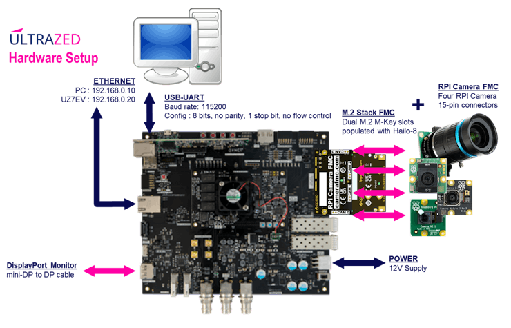
I arranged the Raspberry Pi cameras as shown in the following image:
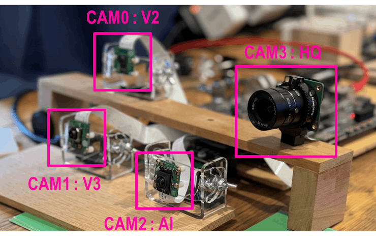
Note that CAM2 (AI camera) is mounted upside down when compared to CAM0 (V2) and CAM1 (V3).
Booting the Modified Design
The drivers for the imx219, imx708, imx500, and imx477 can be queried using the dmesg utility:
root@uzev-hailo-2024-1:~# dmesg | grep imx
[    2.027443] imx477 4-001a: Device found is imx477
[    2.041730] imx708 2-001a: camera module ID 0x0302
[    4.436469] imx500 3-001a: Device found is imx500

root@uzev-hailo-2024-1:~# dmesg | grep rp2040
[    1.983796] rp2040-gpio-bridge 3-0040: rp2040_gbdg_probe() found dev ID: 2d2a4d47682464eb, fw ver. 15
[    1.993789] rp2040-gpio-bridge 3-0040: Could not parse fast_xfer-gpios phandles
The imx219, imx708, imx500, and imx477 are recognized by V4L2 framework. Details can be obtained with the v4l2-ctl and media-ctl utilities:
root@uzev-hailo-2024-1:~# v4l2-ctl --list-devices
Xilinx Video Composite Device (platform:vcap_mipi_0_v_proc):
        /dev/media0
vcap_mipi_0_v_proc output 0 (platform:vcap_mipi_0_v_proc:0):
        /dev/video0
Xilinx Video Composite Device (platform:vcap_mipi_1_v_proc):
        /dev/media1
vcap_mipi_1_v_proc output 0 (platform:vcap_mipi_1_v_proc:0):
        /dev/video1
Xilinx Video Composite Device (platform:vcap_mipi_2_v_proc):
        /dev/media2
vcap_mipi_2_v_proc output 0 (platform:vcap_mipi_2_v_proc:0):
        /dev/video2
Xilinx Video Composite Device (platform:vcap_mipi_3_v_proc):
        /dev/media3
vcap_mipi_3_v_proc output 0 (platform:vcap_mipi_3_v_proc:0):
        /dev/video3
root@uzev-hailo-2024-1:~# media-ctl -p -d /dev/media0
Media controller API version 6.6.10
Media device information
------------------------
driver          xilinx-video
model           Xilinx Video Composite Device
serial
bus info        platform:vcap_mipi_0_v_proc
hw revision     0x0
driver version  6.6.10
Device topology
- entity 1: vcap_mipi_0_v_proc output 0 (1 pad, 1 link)
            type Node subtype V4L flags 0
            device node name /dev/video0
        pad0: Sink
                <- "a0040000.v_proc_ss":1 [ENABLED]
- entity 5: 80050000.mipi_csi2_rx_subsystem (2 pads, 2 links)
            type V4L2 subdev subtype Unknown flags 0
            device node name /dev/v4l-subdev0
        pad0: Sink
                [fmt:SRGGB10_1X10/1920x1080 field:none colorspace:srgb]
                <- "imx219 1-0010":0 [ENABLED]
        pad1: Source
                [fmt:SRGGB10_1X10/1920x1080 field:none colorspace:srgb]
                -> "a0010000.ISPPipeline_accel":0 [ENABLED]
- entity 8: imx219 1-0010 (2 pads, 1 link)
            type V4L2 subdev subtype Sensor flags 0
            device node name /dev/v4l-subdev1
        pad0: Source
                [fmt:SRGGB10_1X10/3280x2464 field:none colorspace:raw xfer:none quantization:full-range
                 crop.bounds:(8,8)/3280x2464
                 crop:(8,8)/3280x2464]
                -> "80050000.mipi_csi2_rx_subsystem":0 [ENABLED]
        pad1: Source
                [fmt:unknown/16384x1 field:none
                 crop.bounds:(8,8)/3280x2464
                 crop:(8,8)/3280x2464]
- entity 11: a0010000.ISPPipeline_accel (2 pads, 2 links)
             type V4L2 subdev subtype Unknown flags 0
             device node name /dev/v4l-subdev2
        pad0: Sink
                [fmt:SRGGB10_1X10/64x64 field:none colorspace:srgb]
                <- "80050000.mipi_csi2_rx_subsystem":1 [ENABLED]
        pad1: Source
                [fmt:RBG888_1X24/64x64 field:none colorspace:srgb]
                -> "a0040000.v_proc_ss":0 [ENABLED]
- entity 14: a0040000.v_proc_ss (2 pads, 2 links)
             type V4L2 subdev subtype Unknown flags 0
             device node name /dev/v4l-subdev3
        pad0: Sink
                [fmt:VYYUYY8_1X24/1280x720 field:none colorspace:srgb]
                <- "a0010000.ISPPipeline_accel":1 [ENABLED]
        pad1: Source
                [fmt:VYYUYY8_1X24/1920x1080 field:none colorspace:srgb]
                -> "vcap_mipi_0_v_proc output 0":0 [ENABLED]
root@uzev-hailo-2024-1:~# media-ctl -p -d /dev/media1
Media controller API version 6.6.10
Media device information
------------------------
driver          xilinx-video
model           Xilinx Video Composite Device
serial
bus info        platform:vcap_mipi_1_v_proc
hw revision     0x0
driver version  6.6.10
Device topology
- entity 1: vcap_mipi_1_v_proc output 0 (1 pad, 1 link)
            type Node subtype V4L flags 0
            device node name /dev/video1
        pad0: Sink
                <- "a00c0000.v_proc_ss":1 [ENABLED]
- entity 5: 80051000.mipi_csi2_rx_subsystem (2 pads, 2 links)
            type V4L2 subdev subtype Unknown flags 0
            device node name /dev/v4l-subdev4
        pad0: Sink
                [fmt:SRGGB10_1X10/1920x1080 field:none colorspace:srgb]
                <- "imx708_wide":0 [ENABLED]
        pad1: Source
                [fmt:SRGGB10_1X10/1920x1080 field:none colorspace:srgb]
                -> "a0030000.ISPPipeline_accel":0 [ENABLED]
- entity 8: imx708_wide (2 pads, 1 link)
            type V4L2 subdev subtype Sensor flags 0
            device node name /dev/v4l-subdev5
        pad0: Source
                [fmt:SRGGB10_1X10/4608x2592 field:none colorspace:raw xfer:none ycbcr:601 quantization:full-range
                 crop.bounds:(16,24)/4608x2592
                 crop:(16,24)/4608x2592]
                -> "80051000.mipi_csi2_rx_subsystem":0 [ENABLED]
        pad1: Source
                [fmt:unknown/28800x1 field:none
                 crop.bounds:(16,24)/4608x2592
                 crop:(16,24)/4608x2592]
- entity 11: a0030000.ISPPipeline_accel (2 pads, 2 links)
             type V4L2 subdev subtype Unknown flags 0
             device node name /dev/v4l-subdev6
        pad0: Sink
                [fmt:SRGGB10_1X10/64x64 field:none colorspace:srgb]
                <- "80051000.mipi_csi2_rx_subsystem":1 [ENABLED]
        pad1: Source
                [fmt:RBG888_1X24/64x64 field:none colorspace:srgb]
                -> "a00c0000.v_proc_ss":0 [ENABLED]
- entity 14: a00c0000.v_proc_ss (2 pads, 2 links)
             type V4L2 subdev subtype Unknown flags 0
             device node name /dev/v4l-subdev7
        pad0: Sink
                [fmt:VYYUYY8_1X24/1280x720 field:none colorspace:srgb]
                <- "a0030000.ISPPipeline_accel":1 [ENABLED]
        pad1: Source
                [fmt:VYYUYY8_1X24/1920x1080 field:none colorspace:srgb]
                -> "vcap_mipi_1_v_proc output 0":0 [ENABLED]
root@uzev-hailo-2024-1:~# media-ctl -p -d /dev/media2
Media controller API version 6.6.10
Media device information
------------------------
driver          xilinx-video
model           Xilinx Video Composite Device
serial
bus info        platform:vcap_mipi_2_v_proc
hw revision     0x0
driver version  6.6.10
Device topology
- entity 1: vcap_mipi_2_v_proc output 0 (1 pad, 1 link)
            type Node subtype V4L flags 0
            device node name /dev/video2
        pad0: Sink
                <- "a0100000.v_proc_ss":1 [ENABLED]
- entity 5: imx500 3-001a (2 pads, 1 link)
            type V4L2 subdev subtype Sensor flags 0
            device node name /dev/v4l-subdev8
        pad0: Source
                [fmt:SRGGB10_1X10/2028x1520 field:none colorspace:raw xfer:none ycbcr:601 quantization:full-range
                 crop.bounds:(8,16)/4056x3040
                 crop:(8,16)/4056x3040]
                -> "80052000.mipi_csi2_rx_subsystem":0 [ENABLED]
        pad1: Source
                [fmt:unknown/10144x1 field:none
                 crop.bounds:(8,16)/4056x3040
                 crop:(8,16)/4056x3040]
- entity 8: 80052000.mipi_csi2_rx_subsystem (2 pads, 2 links)
            type V4L2 subdev subtype Unknown flags 0
            device node name /dev/v4l-subdev9
        pad0: Sink
                [fmt:SRGGB10_1X10/2028x1520 field:none colorspace:srgb]
                <- "imx500 3-001a":0 [ENABLED]
        pad1: Source
                [fmt:SRGGB10_1X10/2028x1520 field:none colorspace:srgb]
                -> "a0090000.ISPPipeline_accel":0 [ENABLED]
- entity 11: a0090000.ISPPipeline_accel (2 pads, 2 links)
             type V4L2 subdev subtype Unknown flags 0
             device node name /dev/v4l-subdev10
        pad0: Sink
                [fmt:SRGGB10_1X10/1920x1232 field:none colorspace:srgb]
                <- "80052000.mipi_csi2_rx_subsystem":1 [ENABLED]
        pad1: Source
                [fmt:RBG888_1X24/1920x1232 field:none colorspace:srgb]
                -> "a0100000.v_proc_ss":0 [ENABLED]
- entity 14: a0100000.v_proc_ss (2 pads, 2 links)
             type V4L2 subdev subtype Unknown flags 0
             device node name /dev/v4l-subdev11
        pad0: Sink
                [fmt:RBG888_1X24/1920x1232 field:none colorspace:srgb]
                <- "a0090000.ISPPipeline_accel":1 [ENABLED]
        pad1: Source
                [fmt:RBG888_1X24/640x480 field:none colorspace:srgb]
                -> "vcap_mipi_2_v_proc output 0":0 [ENABLED]
root@uzev-hailo-2024-1:~# media-ctl -p -d /dev/media3
Media controller API version 6.6.10
Media device information
------------------------
driver          xilinx-video
model           Xilinx Video Composite Device
serial
bus info        platform:vcap_mipi_3_v_proc
hw revision     0x0
driver version  6.6.10
Device topology
- entity 1: vcap_mipi_3_v_proc output 0 (1 pad, 1 link)
            type Node subtype V4L flags 0
            device node name /dev/video3
        pad0: Sink
                <- "a0180000.v_proc_ss":1 [ENABLED]
- entity 5: 80053000.mipi_csi2_rx_subsystem (2 pads, 2 links)
            type V4L2 subdev subtype Unknown flags 0
            device node name /dev/v4l-subdev12
        pad0: Sink
                [fmt:SRGGB10_1X10/1920x1080 field:none colorspace:srgb]
                <- "imx477 4-001a":0 [ENABLED]
        pad1: Source
                [fmt:SRGGB10_1X10/1920x1080 field:none colorspace:srgb]
                -> "a00b0000.ISPPipeline_accel":0 [ENABLED]
- entity 8: imx477 4-001a (2 pads, 1 link)
            type V4L2 subdev subtype Sensor flags 0
            device node name /dev/v4l-subdev13
        pad0: Source
                [fmt:SRGGB12_1X12/4056x3040 field:none colorspace:raw xfer:none ycbcr:601 quantization:full-range
                 crop.bounds:(8,16)/4056x3040
                 crop:(8,16)/4056x3040]
                -> "80053000.mipi_csi2_rx_subsystem":0 [ENABLED]
        pad1: Source
                [fmt:unknown/16384x1 field:none
                 crop.bounds:(8,16)/4056x3040
                 crop:(8,16)/4056x3040]
- entity 11: a00b0000.ISPPipeline_accel (2 pads, 2 links)
             type V4L2 subdev subtype Unknown flags 0
             device node name /dev/v4l-subdev14
        pad0: Sink
                [fmt:SRGGB10_1X10/64x64 field:none colorspace:srgb]
                <- "80053000.mipi_csi2_rx_subsystem":1 [ENABLED]
        pad1: Source
                [fmt:RBG888_1X24/64x64 field:none colorspace:srgb]
                -> "a0180000.v_proc_ss":0 [ENABLED]
- entity 14: a0180000.v_proc_ss (2 pads, 2 links)
             type V4L2 subdev subtype Unknown flags 0
             device node name /dev/v4l-subdev15
        pad0: Sink
                [fmt:VYYUYY8_1X24/1280x720 field:none colorspace:srgb]
                <- "a00b0000.ISPPipeline_accel":1 [ENABLED]
        pad1: Source
                [fmt:VYYUYY8_1X24/1920x1080 field:none colorspace:srgb]
                -> "vcap_mipi_3_v_proc output 0":0 [ENABLED]
root@uzev-hailo-2024-1:~#root@uzev-hailo-2024-1:~#
Writing Applications for the Modified Design
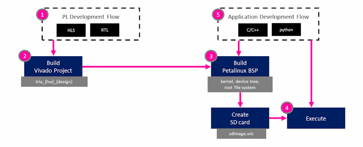
Roadmap : Writing Applications for the Modified Design (: AlbertaBeef)
As an application example, we will modify our “displaycams_yuyv.sh” and “displaycams_bgr.sh” scripts that we created in the previous project.
We first need to update the resolution of the image sensor for each camera:
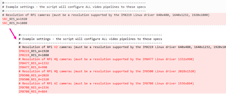

Then we will add new dictionaries for sensor and resolution for each camera:

Then we will fill these new dictionaries with the information for each camera:
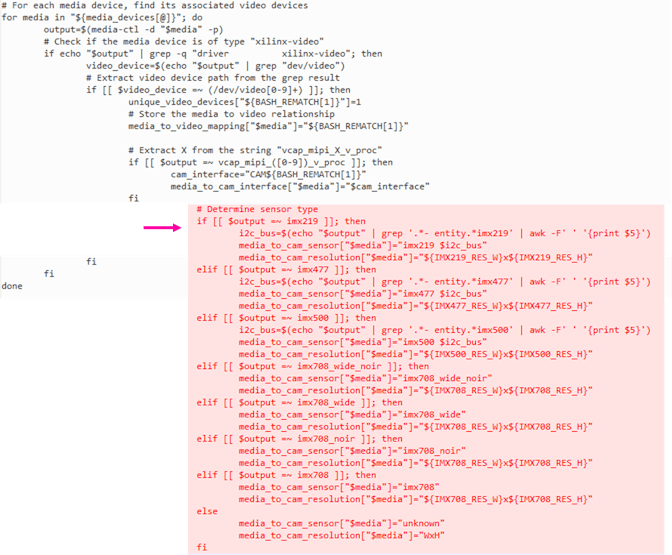
Finally, we need to update the camera configurations:
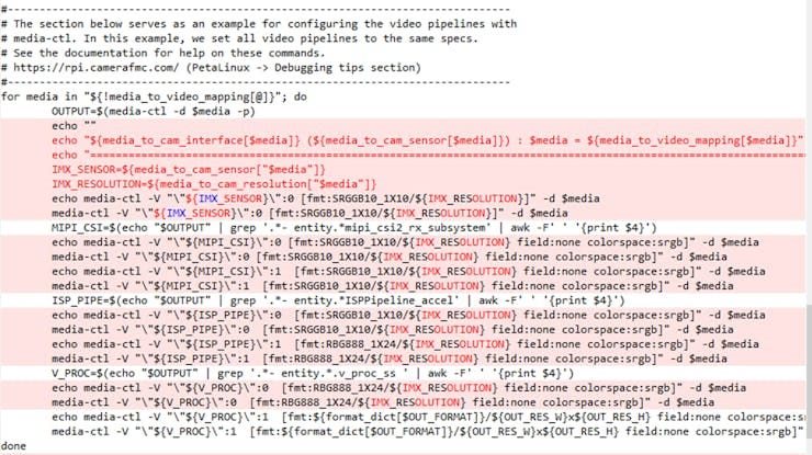
If we launch the “displaycams_bgr.sh” script:
root@uzev-hailo-2024-1:~# ./displaycams_bgr.sh
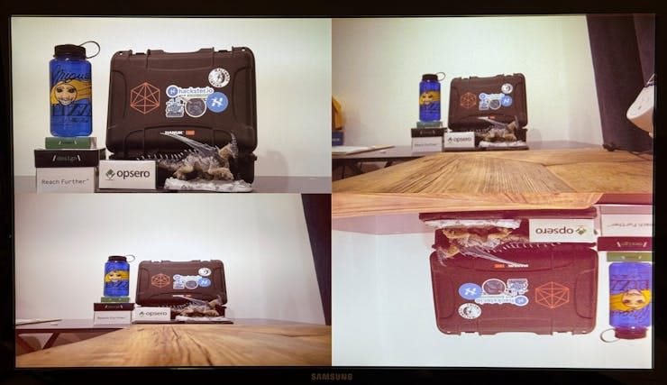
Notice that the HQ camera’s image is upside down, simply because I was not able to mount the camera in the appropriate orientation.
The AI camera’s image was also upside down, so I mounted it upside down on the camera holder.
The RPI Camera V3’s auto-focus functionality does not seem to be available in our design. The focus can be change manually, however, as shown below:
root@uzev-hailo-2024-1:~# v4l2-ctl --list-ctrls -d /dev/video1
User Controls
            exposure 0x00980911 (int)    : min=1 max=874 step=1 default=874 value=874
     horizontal_flip 0x00980914 (bool)   : default=0 value=0 flags=grabbed, modify-layout
       vertical_flip 0x00980915 (bool)   : default=0 value=0 flags=grabbed, modify-layout
low_latency_controls 0x0098ca21 (int)    : min=2 max=8 step=1 default=4 value=4
            red_gain 0x0098ca61 (int)    : min=0 max=65535 step=1 default=100 value=100 flags=slider
           blue_gain 0x0098ca62 (int)    : min=0 max=65535 step=1 default=350 value=351 flags=slider
              awb_en 0x0098ca63 (bool)   : default=1 value=1 flags=slider
           threshold 0x0098ca64 (int)    : min=0 max=65535 step=1 default=512 value=512 flags=slider
           red_gamma 0x0098ca65 (int)    : min=1 max=40 step=1 default=20 value=20 flags=slider
         green_gamma 0x0098ca66 (int)    : min=1 max=40 step=1 default=15 value=15 flags=slider
          blue_gamma 0x0098ca67 (int)    : min=1 max=40 step=1 default=20 value=20 flags=slider

Camera Controls
        focus_absolute 0x009a090a (int)    : min=0 max=1023 step=1 default=480 value=480
    wide_dynamic_range 0x009a0915 (bool)   : default=0 value=0 flags=grabbed, modify-layout
    camera_orientation 0x009a0922 (menu)   : min=0 max=2 default=2 value=2 (External) flags=read-only
camera_sensor_rotation 0x009a0923 (int)    : min=180 max=180 step=1 default=180 value=180 flags=read-only

Image Source Controls
     vertical_blanking 0x009e0901 (int)    : min=40 max=8387616 step=1 default=2755 value=58
   horizontal_blanking 0x009e0902 (int)    : min=3680 max=3680 step=1 default=3680 value=3680 flags=read-only
         analogue_gain 0x009e0903 (int)    : min=112 max=960 step=1 default=112 value=112
       red_pixel_value 0x009e0904 (int)    : min=0 max=4095 step=1 default=4095 value=4095
 green_red_pixel_value 0x009e0905 (int)    : min=0 max=4095 step=1 default=4095 value=4095
      blue_pixel_value 0x009e0906 (int)    : min=0 max=4095 step=1 default=4095 value=4095
green_blue_pixel_value 0x009e0907 (int)    : min=0 max=4095 step=1 default=4095 value=4095
          notify_gains 0x009e0909 (int)    : min=1 max=65535 step=1 default=256 dims=[4] flags=has-payload

Image Processing Controls
        link_frequency 0x009f0901 (intmenu): min=0 max=0 default=0 value=0 (450000000 0x1ad27480) flags=read-only
            pixel_rate 0x009f0902 (int64)  : min=566400000 max=566400000 step=1 default=566400000 value=566400000 flags=read-only
          test_pattern 0x009f0903 (menu)   : min=0 max=4 default=0 value=0 (Disabled)
          digital_gain 0x009f0905 (int)    : min=256 max=65535 step=1 default=256 value=256

root@uzev-hailo-2024-1:~# v4l2-ctl -d /dev/video1 --set-ctrl focus_absolute=1000
root@uzev-hailo-2024-1:~# v4l2-ctl -d /dev/video1 --set-ctrl focus_absolute=100
root@uzev-hailo-2024-1:~# v4l2-ctl -d /dev/video1 --set-ctrl focus_absolute=256
root@uzev-hailo-2024-1:~# v4l2-ctl -d /dev/video1 --set-ctrl focus_absolute=128
root@uzev-hailo-2024-1:~# v4l2-ctl -d /dev/video1 --set-ctrl focus_absolute=300
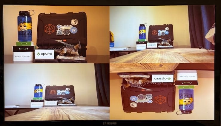
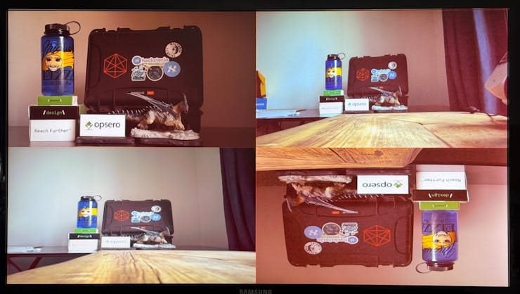
If we change the lighting, we can see that the images will change significantly. We will take a deeper look at the white balance occurring with the ISPPipeline core and driver in the next project.
Known Issues
The following issues are currently unresolved:
- vertical/horizontal flip controls not working for all cameras
- auto-focus functionality for Camera V3 (IMX708 + DW9817) not available
- AI functionality for AI Camera (IMX500 + RP2040) not available
Acknowledgements
I want to thank Jeff Johnson (Opsero) for his excellent reference design, as well as his fabulous portfolio of FMC hardware:
- [Opsero] RPI Camera FMC
- [Opsero] M.2 M-key Stack FMC
I also want to thank Gianluca Filippini (EBV) for his pioneering work with the Hailo-8 AI Accelerator module, and bringing this marvel to my attention. His feedback, guidance, and insight have been invaluable.
- [Hailo] Hailo-8 AI Acceleration module
Version History
- 2024/12/30 — Initial Version
References
- [Raspberry Pi] RPI Camera Portfolio
- [AMD] Kria AI Vision Kit — NLP-SmartVision app
- [Opsero] RPI Camera FMC Reference Design
- [Ospero] RPI Camera FMC Reference Design — Building
- [Ospero] RPI Camera FMC Reference Design — Modifying
- [AMD/Xilinx] DRM KMS Driver
- [AMD/Xilinx] Video Mixer — Linux Driver
- [AMD/Xilinx] ZynqMP DisplayPort Controller — Linux Driver
- [AMD/Xilinx] MIPI CSI-2 RX — Linux Driver
- [AMD/Xilinx] ISPPipeline — Linux Driver

