


Introduction
This project is part 3 of a N part series of projects, where we will explore how to integrate Raspberry Pi cameras on Zynq-UltraScale+ boards.
- Part 1 : RPI Camera Fun with Zynq-UltraScale+ : RPI Cam V2
- Part 2 : RPI Camera Fun with Zynq-UltraScale+ : RPI Cam V3, HQ, AI
- Part 3 : RPI Camera Fun with Zynq-UltraScale+ : White Balance
- Part 4 : RPI Camera Fun with Zynq-UltraScale+ : LIBCAMERA
During this series, I will be targeting the following hardware setup:
- Tria UltraZed-7EV Starter Kit (SOM + Carrier Card)
- Opsero RPI Camera FMC
- Raspberry Pi cameras
The featured design will also support Hailo-8 AI acceleration with the following optional hardware:
- Opsero M.2 Stack FMC
- Hailo-8 AI Acceleration module
The motivation of this series of projects is to enable users to leverage Raspberry Pi’s wonderful portfolio of cameras and supporting software, on Zynq-UltraScale+ hardware.
Introduction — Part III
This project focuses on exploring the image quality of our design.
I will start with an overview of the HLS-based ISP implementation in our design.
Then, I will perform a quick visual comparison of image quality for the V2 and V3 camera modules for the following platforms:
- UltraZed-EV : AMD HLS-based ISPPipeline
- Raspbery Pi 5 : PiSP (Front End + Back End) + LIBCAMERA
Then I will provide a brief overview of how we can numerically measure the White Balance and Color Correctness of the images generated by our design, and once again compare this to the RPI5.
Finally, I will conclude with an existential discussion on ISP quality, in the context of various applications.
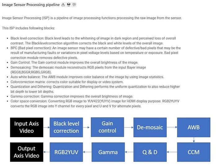
Overview of the HLS-based ISP
The ISP implemented in our design is an open-source HLS-based implementation.
 : AMD/Xilinx)
As can be seen, the ISP is composed of several processing blocks, which each can be configured and/or rfrom the pipeline.
Recall from the previous projects that our ISP’s configuration is defined by the following file:
isppipeline/include/xf_config_params.h
// (C) Copyright 2023 Advanced Micro Devices, Inc. All rights reserved.
// SPDX-License-Identifier: Apache-2.0

#ifndef _XF_ISP_TYPES_H_
#define _XF_ISP_TYPES_H_
// --------------------------------------------------------------------
// Required files
// --------------------------------------------------------------------
#include "hls_stream.h"
#include "ap_int.h"
#include "common/xf_common.hpp"
//#include "common/xf_utility.h"
#include "ap_axi_sdata.h"
#include "common/xf_axi_io.hpp"
// Requried Vision modules
#include "imgproc/xf_bpc.hpp"
#include "imgproc/xf_gaincontrol.hpp"
#include "imgproc/xf_autowhitebalance.hpp"
#include "imgproc/xf_demosaicing.hpp"
#include "imgproc/xf_ltm.hpp"
#include "imgproc/xf_quantizationdithering.hpp"
#include "imgproc/xf_lensshadingcorrection.hpp"
#include "imgproc/xf_colorcorrectionmatrix.hpp"
#include "imgproc/xf_black_level.hpp"
#include "imgproc/xf_aec.hpp"
#include "imgproc/xf_cvt_color.hpp"
#include "imgproc/xf_cvt_color_1.hpp"
#include "imgproc/xf_gammacorrection.hpp"
//#define XF_WIDTH 1920
// MAX_COLS
//#define XF_HEIGHT 1080
// MAX_ROWS
#define XF_WIDTH 4096
#define XF_HEIGHT 4096

#define XF_CV_DEPTH_IN_1 2
#define XF_CV_DEPTH_IN_2 2
#define XF_CV_DEPTH_BPC_OUT 2
#define XF_CV_DEPTH_GAIN_OUT 2
#define XF_CV_DEPTH_DEMOSAIC_OUT 2
#define XF_CV_DEPTH_IMPOP 2
#define XF_CV_DEPTH_LTM_IN 2
#define XF_CV_DEPTH_LSC_OUT 2
#define XF_CV_DEPTH_DST 2
#define XF_CV_DEPTH_AEC_IN 2
#define XF_CV_DEPTH_OUT 2
//#define NPPCX XF_NPPC2
#define NPPCX XF_NPPC1
//#define XF_BAYER_PATTERN XF_BAYER_GR
#define XF_BAYER_PATTERN XF_BAYER_RG
// bayer pattern
#define T_8U 0
#define T_10U 1
#define T_12U 0
#define T_16U 0
#define XF_CCM_TYPE XF_CCM_bt2020_bt709
#define XF_LTM_T XF_8UC3
// XF_8UC3
#define IN_TYPE XF_10UC1
// XF_8UC1
#define OUT_TYPE XF_10UC3
// XF_8UC3
...
#define SIN_CHANNEL_TYPE XF_8UC1
#define WB_TYPE XF_WB_SIMPLE
#define AEC_EN 0
#define XF_AXI_GBR 1
//#define XF_USE_URAM 0
// uram enable not implemented correctly needs correction
#define XF_USE_URAM 1
#define S_DEPTH 4096
// --------------------------------------------------------------------
// Macros definitions
// --------------------------------------------------------------------
...
// --------------------------------------------------------------------
// Internal types
// --------------------------------------------------------------------
// Input/Output AXI video buses
typedef ap_axiu<AXI_WIDTH_IN, 1, 1, 1> InVideoStrmBus_t;
typedef ap_axiu<AXI_WIDTH_OUT, 1, 1, 1> OutVideoStrmBus_t;
// Input/Output AXI video stream
typedef hls::stream<InVideoStrmBus_t> InVideoStrm_t;
typedef hls::stream<OutVideoStrmBus_t> OutVideoStrm_t;
#if T_8U
#define HIST_SIZE 256
#endif
#if T_10U
#define HIST_SIZE 1024
#endif
#if T_12U
#define HIST_SIZE 4096
#endif
#if T_16U
#define HIST_SIZE 4096
#endif
#define BLACK_LEVEL 32
...
// --------------------------------------------------------------------
// Prototype
// --------------------------------------------------------------------
// top level function for HW synthesis
void ISPPipeline_accel(uint16_t width,
                       uint16_t height,
                       InVideoStrm_t& s_axis_video,
                       OutVideoStrm_t& m_axis_video,
                       uint16_t rgain,
                       uint16_t bgain,
                       unsigned char r_lut[256 * 3],
                       unsigned char mode_reg,
                       uint16_t pawb);
#endif
Also, our ISP is controlled by the following linux driver:
- [AMD/Xilinx] ISPPipeline — Linux Driver
We can observe that there is no AWB code in the linux driver, nor is there a control to read the image statistics, generated by this module. This means that the AWB algorithm in completely implemented in hardware, which creates a very “tight” control loop.
The module that implements this algorithm is documented here:
Although the documentation does not go in depth of the AWB algorithm, it does refer to two algorithms:
- Grayworld whitebalancing algorithm
- Simple whitebalancing algorithm
Although the code is open-source, there is no documentation available:
A Quick Comparison of our ISP with the RPI5 Reference
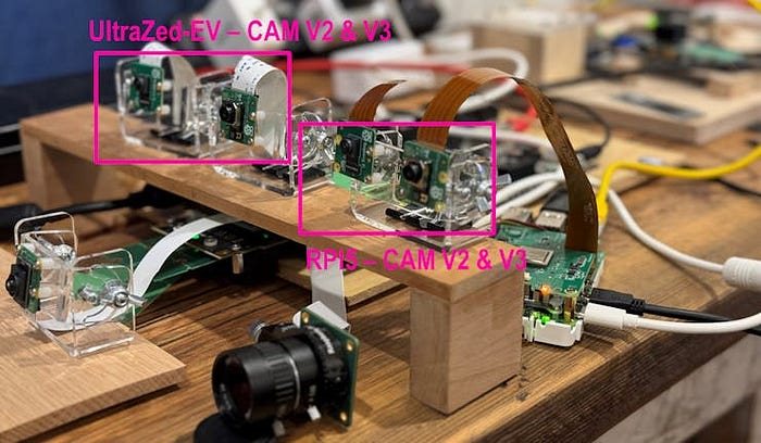
In order to perform a quick visual comparison of how our ISP with the Raspberry Pi’s PiSP, I have chosen the following two camera modules:
- RPI Cam V2
- RPI Cam V3 (in my case, wide variant)
I placed the Raspberry Pi 5 kit with the two camera modules mounted along side the ones in our UltraZed-EV design, as shown below:
 : AlbertaBeef)
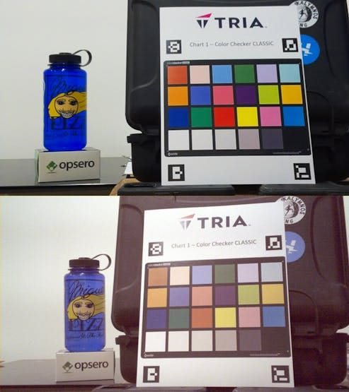
For the V2 camera module, when compared to the RPI5 implementation, has good color, but seems washed out (flat) and grainy (noisy):
 : AlbertaBeef)
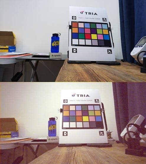
Similarly, for the V3 camera module, when compared to the RPI5 implementation, has good color, but seems washed out (flat) and grainy (noisy):
 : AlbertaBeef)
What is the cause of this difference ?
Although there may be image sensor settings that are different, the main difference is the ISP.
White Balance and Color Correction
In 2012, I had the privilege of working on a custom ISP for the Zynq-7000 target.
We implemented a custom Image Processing Pipeline (ISP) for the Zynq-7000 embedded platform. I was in charge of coding the implementation on the Zynq Video and Imaging Kit (ZVIK).
I had the honor of presenting our results at the Embedded Vision Summit in 2012 :
 : Embedded Vision Summit)
The work ultimately ended up being documented as Xilinx App Note XAPP794 : 1080P60 Camera Image Processing Reference Design
As well as being featured in an Excel article:
Good times !
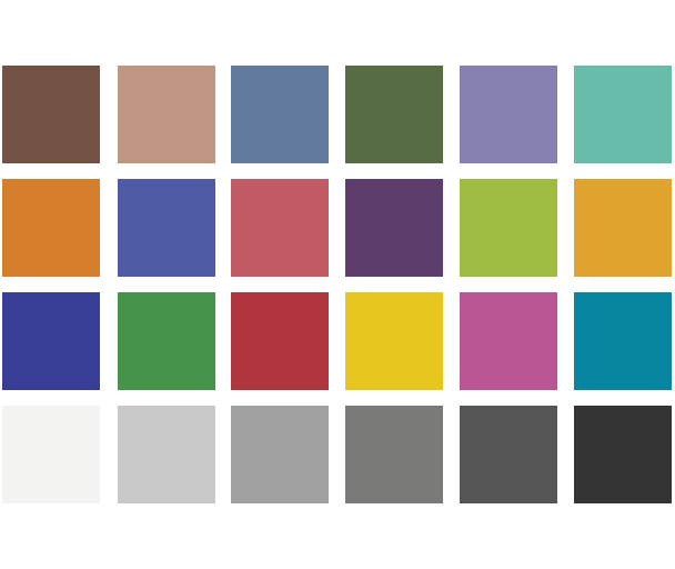
My main take-away from this experience was learning about colorchecker charts, such as this one:
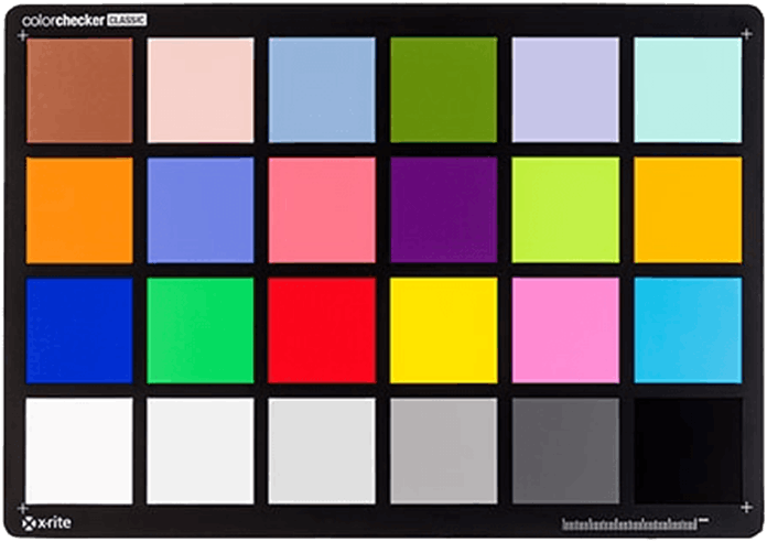 : x-rite)
This allows a system to measure the color correctness in an image, based on a chart of known colors. The colors each have a unique name and BGR composition:
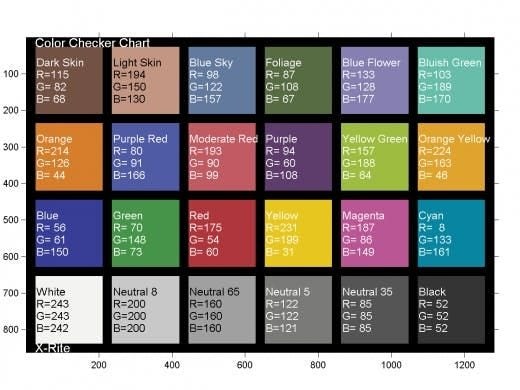 : https://mrsdprojects.ri.cmu.edu/2016teamg/color-calibration )
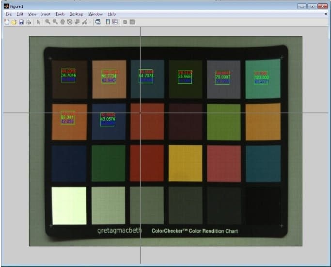
Back in 2012, we used a tedious method of detecting the color chart by manually selecting points on the chart in the image:
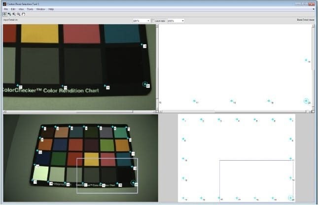 : XAPP794)
This allowed the chart to be un-warped, as shown below:
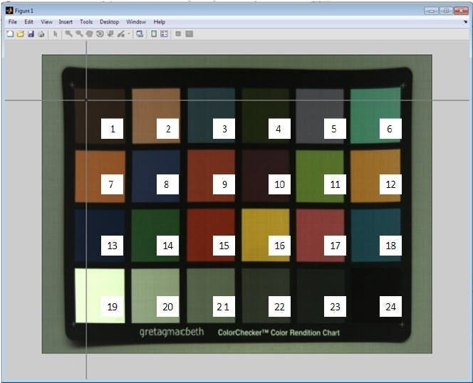 : XAPP794)
Then we also had to select the patch for each color square, to determine its average BGR values.
 : XAPP794)
We will automate this tedious process, as discussed in the next section.
With ROIs identified for each color patch, we can compare the captured colors with the known ground truth.
Automatic Chart Detection
I will be reusing an old project I did back in 2021 to detect charts using ArUco markers:
 : AlbertaBeef)
At that time, I defined the following three charts:
- Chart 1 : Checkerboard (9x7)
- Chart 2: White Reference
- Chart 3: Histogram
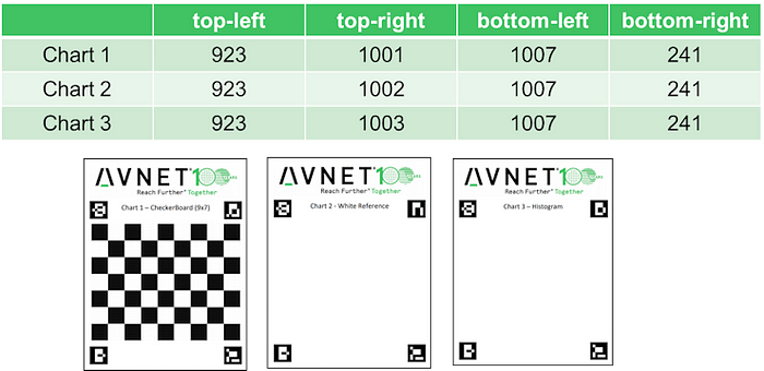 : AlbertaBeef)
The Checkboard chart never got used for anything, so I re-defined it for the ColorChecker chart.
- Chart 1 : Color Checker CLASSIC
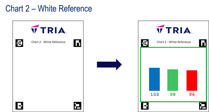
- Chart 2: White Reference
- Chart 3: Histogram
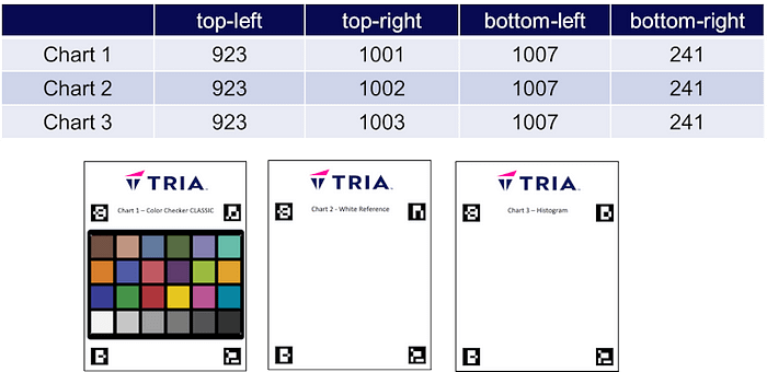 : AlbertaBeef)
The “White Reference” and “Histogram” charts will be used the same way, presenting the system with a “white region” inside the four ArUco markers.
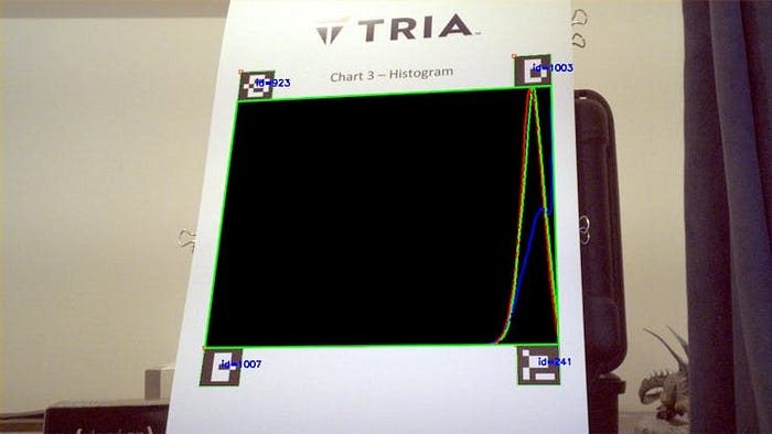
The “Histogram” chart is used to create the histogram of BGR components, in the white region of the chart:
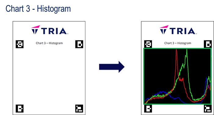 : AlbertaBeef)
The “White Reference” chart is used to compute the average value of the BGR components in the white region of the chart.
 : AlbertaBeef)
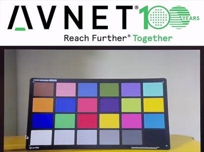
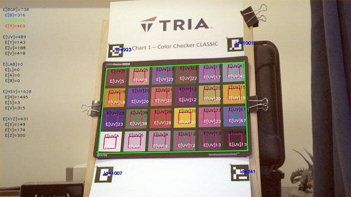
The “Color Checker CLASSIC” chart will be used in collaboration with a true “x-rite colorchecker CLASSIC”:
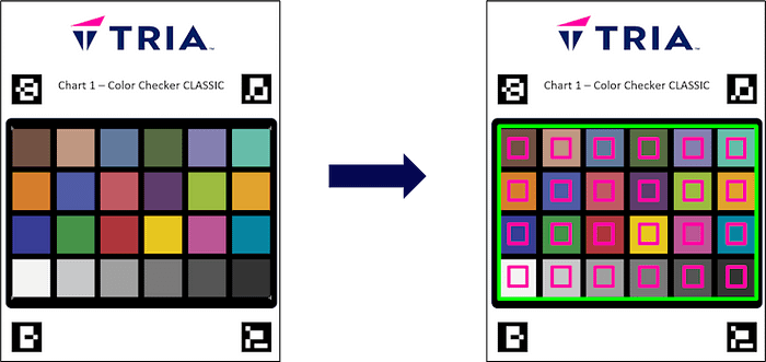 : AlbertaBeef)
The chart automates the tedious process of identifying ROIs for each color square on the chart, for further analysis for color correctness.
The GStreamer plug-in implementing the detection of the charts, and associated processing, can optionally call scripts for certain charts:
- chart 1 : Color Checker => cc-script
- chart 2 : White Balance => wb-script
The following image summarizes the arguments that enable the cc-script for the “Color Checker” chart:
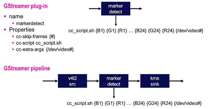 : AlbertaBeef)
The following image summarizes the arguments that enable the wb-script for the “White Balance” chart:
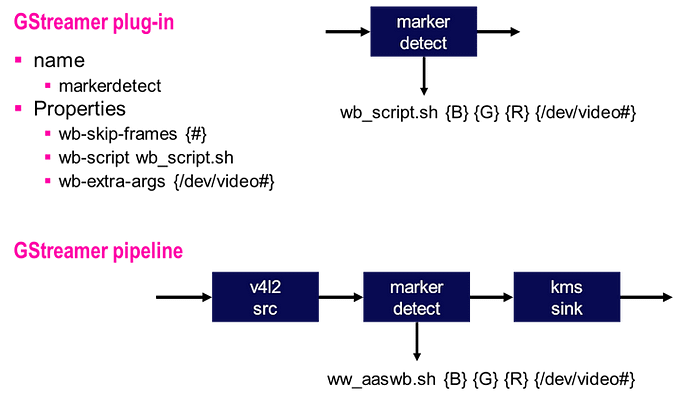 : AlbertaBeef)
Validating the Chart Detection
In order to validate the detection of the charts, I implemented the following four GStreamer pipelines:
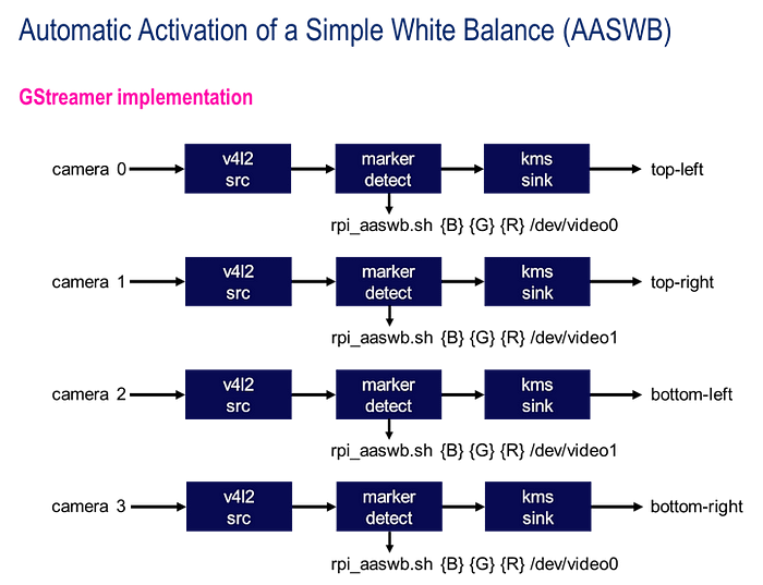 : AlbertaBeef)
Using the design from our previous project, I first installed the “markerdetect” GStreamer plug-in as shown below:
git clone https://github.com/AlbertaBeef/gstmarkerdetect
cd gstmarkerdetect
make
cp libgstmarkerdetect.so /usr/lib/gstreamer-1.0/.
We can query the “markerdetect” GStreamer plug-in using the “gst-inspect-1.0” utility:
root@uzev-hailo-2024-1:~# gst-inspect-1.0 markerdetect
Factory Details:
  Rank                     none (0)
  Long-name                Marker detection using the OpenCV Library
  Klass                    Video Filter
  Description              Marker Detection
  Author                   FIXME <fixme@example.com>

Plugin Details:
  Name                     markerdetect
  Description              Marker detection using the OpenCV Library
  Filename                 /usr/lib/gstreamer-1.0/libgstmarkerdetect.so
  Version                  0.0.0
  License                  LGPL
  Source module            markerdetect
  Binary package           OpenCV Library
  Origin URL               http://avnet.com
GObject
 +----GInitiallyUnowned
       +----GstObject
             +----GstElement
                   +----GstBaseTransform
                         +----GstVideoFilter
                               +----GstMarkerDetect
Pad Templates:
  SINK template: 'sink'
    Availability: Always
    Capabilities:
      video/x-raw
                 format: { (string)BGR }
                  width: [ 1, 1920 ]
                 height: [ 1, 1080 ]
              framerate: [ 0/1, 2147483647/1 ]
  SRC template: 'src'
    Availability: Always
    Capabilities:
      video/x-raw
                 format: { (string)BGR }
                  width: [ 1, 1920 ]
                 height: [ 1, 1080 ]
              framerate: [ 0/1, 2147483647/1 ]
Element has no clocking capabilities.
Element has no URI handling capabilities.
Pads:
  SINK: 'sink'
    Pad Template: 'sink'
  SRC: 'src'
    Pad Template: 'src'
Element Properties:
  name                : The name of the object
                        flags: readable, writable, 0x2000
                        String. Default: "markerdetect0"
  parent              : The parent of the object
                        flags: readable, writable, 0x2000
                        Object of type "GstObject"
  qos                 : Handle Quality-of-Service events
                        flags: readable, writable
                        Boolean. Default: true
  wb-extra-args       : Extra arguments for White Balance script.
                        flags: readable, writable
                        String. Default: null
  wb-script           : White Balance script.
                        flags: readable, writable
                        String. Default: null
  wb-skip-frames      : White Balance skip frames.
                        flags: readable, writable
                        Integer. Range: 0 - 2147483647 Default: 0
Then I downloaded the “displaycams_aaswb.sh” and “rpicam_aaswb.sh” scripts to the embedded platform.
The displaycams_aaswb.sh script makes use of the BGR planes in the Video Mixer.
The rpi_aaswb.sh script adjusts the “blue” and “red” gains so that they match the “green” average values.
The script can be launched as follows:
source ./displaycams_aaswb.sh
A first sanity check of the chart detection seems successful, even when the image is upside down.
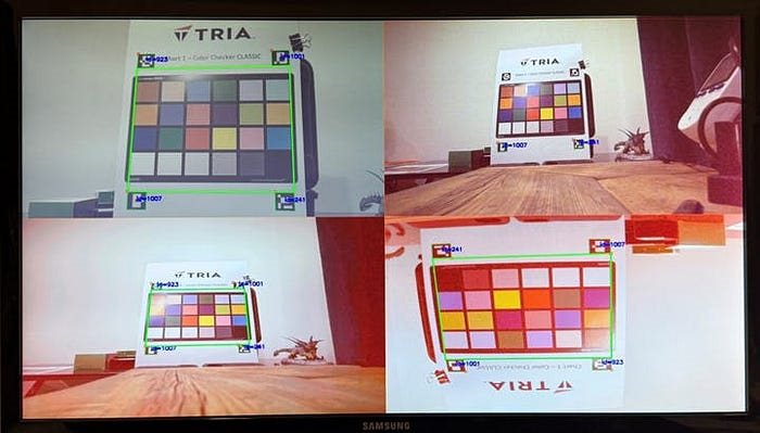 : AlbertaBeef)
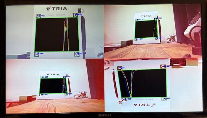 : AlbertaBeef)
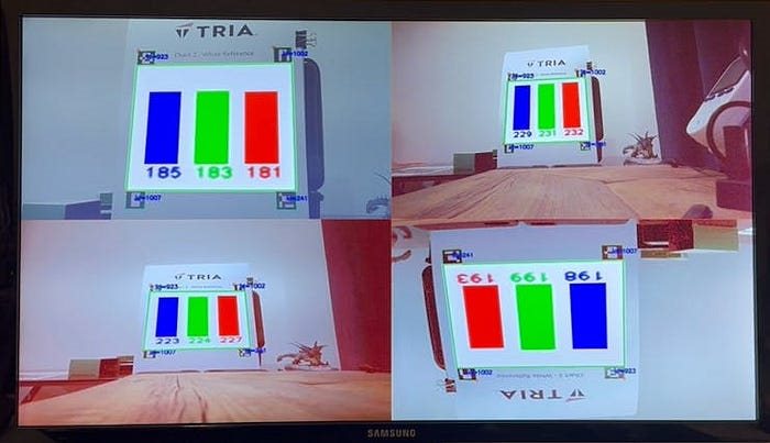 : AlbertaBeef)
The default values from Jeff’s original design seem to work fairly well, with the “White Reference” and “Histogram” charts indicating that the BGR components are similar for our white reference.
In order to validate the AASWB algorithm, I started by boosting the “blue” gain for CAM0, to see if the script could adjust it back to a proper value.
: AlbertaBeef)We can see that for CAM0, the script managed to adjust the “blue” gain to match the average “green” values.
One important detail to consider is that when the chart is not detected (for CAM1 and CAM2, with wider field of view), the AASWB algorithm is not running anymore. This is a limitation of this strategy, which can be caused by occlusion, low light, etc …
Another important detail to notice is that something bizarre is happening with CAM3. Since our processing loop (which is essentially a control loop), is not running fast enough, we are running into a ringing effect, which may be caused by the delay between when the gains are applied, and when we perceive the changes in our script. Regardless of the reason, we will ignore it for now … and concentrate on the first camera (V2).
Measuring the White Balance and Color Correctness
When comparing the image quality between our design (HLS-based ISP) and the Raspberry Pi 5 (with PiSP, and supporting LIBCAMERA stack), we can see that our image is not as good, but this is only a subjective observation.
This section attempts to take measurements that confirms this numerically.
NOTE : For this section, I did not rely on the print quality for my color checker chart. Instead I printed my chart 1.37x larger and placed the actual x-rite Color Checker CLASSIC on top with binder clips, for use as a more reliable color source.
These measurements were done using the gstmarkerdetect plug-in we discussed previously, as well as the libcamerasrc gstreamer plug-in (! spoiler alert !) for both UltraZed-EV and Raspberry Pi 5 platforms.
In order to identify which V4L2 compatible cameras are present, I used libcamera’s “cam -l” application, then call the libcamera_markerdetect.py script using the reported camera name.
On our UltraZed-EV, we run the script with camera “/base/pl-bus/i2c@80040000/sensor@10”:
root@uzev-hailo-2024-1:~/libcamera.xisp_take01/build# cam -l
...
Available cameras:
1: 'imx219' (/base/pl-bus/i2c@80040000/sensor@10)
2: 'imx708_wide' (/base/pl-bus/i2c@80070000/sensor@10)
3: 'imx500' (/base/pl-bus/i2c@80090000/sensor@1a)
4: 'imx477' (/base/pl-bus/i2c@800b0000/sensor@1a)

root@uzev-hailo-2024-1:~/libcamera.xisp_take01/build# cd ../../gstmarkerdetect/test/
root@uzev-hailo-2024-1:~/gstmarkerdetect/test# python3 libcamera_markerdetect.py --input /base/pl-bus/i2c@80040000/sensor@10 --width 1280 --height 720
[INFO] input resolution =  1280 X 720
[INFO] fps overlay =   False
[INFO] ccscript =  None
[INFO] wbscript =  None
[INFO] dev_video =  /dev/video0
[INFO] ccscript =  None
[INFO] wbscript =  None
[INFO] gst_pipeline =  libcamerasrc camera-name=/base/pl-bus/i2c@80040000/sensor@10 ! video/x-raw,width=1280,height=720,format=BGR ! videoconvert ! markerdetect  ! videoconvert ! queue ! appsink
...
[118:59:13.475585062] [9374]  INFO Camera camera.cpp:1202 configuring streams: (0) 1280x720-RBG888
...
On the RPI5, we run the script with camera “/base/axi/pcie@120000/rp1/i2c@88000/imx219@10”:
rpiaikit26@raspberrypi:~ $ cam -l
...
Available cameras:
1: 'imx219' (/base/axi/pcie@120000/rp1/i2c@88000/imx219@10)
2: 'imx708_wide' (/base/axi/pcie@120000/rp1/i2c@80000/imx708@1a)

rpiaikit26@raspberrypi:~ $ cd gstmarkerdetect/test
rpiaikit26@raspberrypi:~/gstmarkerdetect/test $ python3 libcamera_markerdetect.py --input /base/axi/pcie@120000/rp1/i2c@88000/imx219@10 --width 1280 --height 720
[INFO] input resolution =  1280 X 720
[INFO] fps overlay =   False
[INFO] ccscript =  None
[INFO] wbscript =  None
[INFO] dev_video =  /dev/video0
[INFO] ccscript =  None
[INFO] wbscript =  None
[INFO] gst_pipeline =  libcamerasrc camera-name=/base/axi/pcie@120000/rp1/i2c@88000/imx219@10 ! video/x-raw,width=1280,height=720,format=BGR ! videoconvert ! markerdetect  ! videoconvert ! queue ! appsink
...
[833:40:12.284541245] [76284]  INFO Camera camera.cpp:1197 configuring streams: (0) 1280x720-RGB888
...
White Balance Measurement
For the balance of the B, G, and R components, we look at the histogram, and average values.
 : AlbertaBeef)
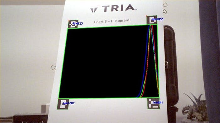 : AlbertaBeef)
We can see that for our design, the three colors (B, G, R) are aligned, except of the blue. This was taken in daylight. The histograms matched very well with office lighting (LEDs).
Color Correctness Measurements
For the correctness of various colors, using the color checker chart, I experimented with different color spaces:
- BGR : unreliable, since subject to intensity
- YUV : much better, since color (chroma, UV) is separated from intensity (Y)
- LAB : better, but not as good as YUV
- HSV : better, but not as good as YUV
- XYZ : tri-stimulus version of BGR, meant to mimic our biological eyes, still unreliable, since subject to intensity
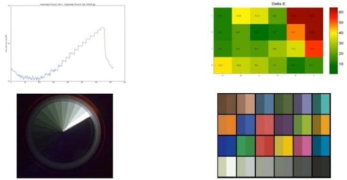
We are comparing with the following ground truth, which was generated with the following script:
 : AlbertaBeef)
For each color space, an error is calculated such that the difference with the ground truth is squared for each component, then summed up.
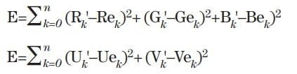 : AlbertaBeef)
Note that for the YUV color space, only the UV components are used in the error calculation.
I use the root squared of these sums for my final results.
 : AlbertaBeef)
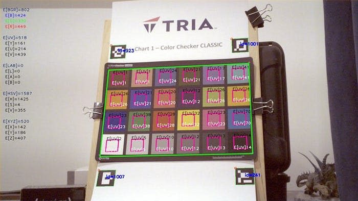 : AlbertaBeef)
Using the BGR and XYZ color spaces, the numerical error is smaller for our design (which does not reflect our observation).
There is something wrong with my LAB error calculation on the UZ7EV platform, which we will ignore for now …
The key take away is that the best representation of color correctness error is with the YUV color space, specifically using the UV components.
Can I do Better ?
I had an idea that if the Red and Blue gains were properly adjusted, the HLS-based AWB algorithm may give a better result.
I did this by adjusting the Red and Blue gains with the AASWB algorithm (described above), while the HLS-based AWB was disabled, then re-enabled it to measure the difference in color correctness.
The following video illustrates my thought process, and the exploration.
: AlbertaBeef)Final result ? The color correctness diminished (UV errors got larger), so no, I was not able to do better.
What Next ?
Although it would be possible to use the cc-script to implement some kind of color correction matrix, the overall implementation would be rather slow, and the control loop would probably not be fast enough to be stable (as we saw for the AASWB loop for CAM3).
We will keep this strategy as a way of quickly measuring the image quality of our system, and compare with improvements we make in the future.
In the next project, I will take on the ambitious goal of adding support for LIBCAMERA to our system. I expect to get the following benefits:
- leverage the infrastructure (libcamera API, python API, gstreamer plug-in, etc…)
- opportunity to implement a real-time control loop for auto white balance (AWB)
How Good is our ISP ?
Image Processing Pipelines (ISPs) have become very complex, and have been designed mainly to reproduce image quality that our biological eyes offer us.
In an AI-enabled system, where we are mostly interested in perceiving our surroundings, is this complexity still necessary for our application ? How to assess when an ISP is good enough ?
Turns out, this is an excellent question. Different applications have different ISP requirements, and thus different ISP implementations.
Leo Petropoulus (Vision System Architect, Xilinx) offers a very interesting overview of ISPs for different applications, with several real world use-cases:
- Break the Bounds of Standard ISPs: A Xilinx Introduction to Custom ISPs (Jan 9, 2020)
https://www.xilinx.com/video/events/introduction-to-custom-isps.html
The author presents an interesting visual representation of color correctness, which I may consider in a future implementation:
 : Xilinx)
In his presentation, Leo Petropoulus compares three different ISP implementations, their numerical color correctness, and their original application target.
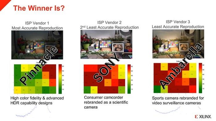 : Xilinx)
The conclusion of this presentation, is that numerical correctness does not necessarily translate to human perception of image quality.
Sony have made many tweaks to their ISP, in order to favor the human perception of their cameras and camcorders.
Ambarella have made different choices, in order to address the sports camera market.
Acknowledgements
Thank you Pantone for your innovative and inspiring color matching app:
- Pantone, Color Matching Card, https://www.pantone.com/pantone-color-match-card
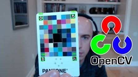 : PyImageSearch)
Thank you Adrian Rosebrock for your excellent tutorials:
- Adrian Rosebrock, Generating ArUco markers with OpenCV and Python, PyImageSearch,https://www.pyimagesearch.com/2020/12/14/generating-aruco-markers-with-opencv-and-python/ (accessed on 07 May, 2021)
- Adrian Rosebrock, Detecting ArUco markers with OpenCV and Python, PyImageSearch, https://www.pyimagesearch.com/2020/12/21/detecting-aruco-markers-with-opencv-and-python/ (accessed on 07 May, 2021)
Thank you Leo Petropoulus (Xilinx) for your very insightful presentation:
- Break the Bounds of Standard ISPs: A Xilinx Introduction to Custom ISPs (Jan 9, 2020)
https://www.xilinx.com/video/events/introduction-to-custom-isps.html
References
- [Pantone] Color Matching Card
- [PyImageSearch] Adrian Rosebrock, Generating ArUco markers with OpenCV and Python
- [PyImageSearch] Adrian Rosebrock, Detecting ArUco markers with OpenCV and Python
- [Embedded Vision Summit] 1080P60 Camera Demo (September, 2012)
- [Xilinx] XAPP794 : 1080P60 Camera Image Processing Reference Design
- [Xilinx] Xcell Journal 2012 : Image Sensor Color Calibration using Zynq-7000 All Programmable SoC
- [AMD/Xilinx] Image Sensor Processing pipeline • Vitis Libraries • Reader • AMD Technical Information Portal
- [AMD/Xilinx] ISPPipeline — Linux Driver
- [AMD/Xilinx] Auto White Balance • Vitis Libraries • Reader • AMD Technical Information Portal
- [AMD/Xilinx] Vitis_Libraries/vision/L1/include/imgproc/xf_autowhitebalance.hpp at main · Xilinx/Vitis_Libraries · GitHub
- [Xilinx] Leo Petropoulus, Break the Bounds of Standard ISPs: A Xilinx Introduction to Custom ISPs (Jan 9, 2020)
Revision History
2025/01/27 — Initial Version
Top Comments
-

DAB
-
Cancel
-
Vote Up
+1
Vote Down
-
-
Sign in to reply
-
More
-
Cancel
Comment-

DAB
-
Cancel
-
Vote Up
+1
Vote Down
-
-
Sign in to reply
-
More
-
Cancel
Children