The Single Rate Half-Band FIR Interpolator
In the previous post we looked at the single rate half-band FIR, a particular type of odd-symmetric FIR, where almost half of the filter coefficients are zero. Not computing multiplications with these zero coefficients and also taking advantage of the symmetry reduces the number of multiplications per output sample by a factor of 4x. From a mathematical point of view, that filter looked like this, for the particular case where the filter order is N=11:
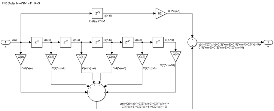
The single rate half-band FIR is rarely used as such, its primary uses are as a two-to-one interpolator or decimator, which are our first examples of a multi-rate FIR. We will consider today the case of the half-band interpolator. The half-band interpolator increases the sample rate of the input data by a factor of 2x. The design is still a single clock rate one, but for every input sample the filter produces two output samples. Conceptually, this is achieved by doubling the input data rate by inserting zero valued samples between the existing ones. This has the effect of creating two identical spectral images of the input signal in the frequency domain. The second undesired image is attenuated by passing this double rate signal through a single rate half-band FIR, the type we have seen in the last post, running at the double sample rate we have created. The output of this filter will be our double sample rate interpolated signal. We will start by removing the zero coefficient multipliers from the design, and also splitting the filter into two branches, reserving one for the center tap coefficient: 

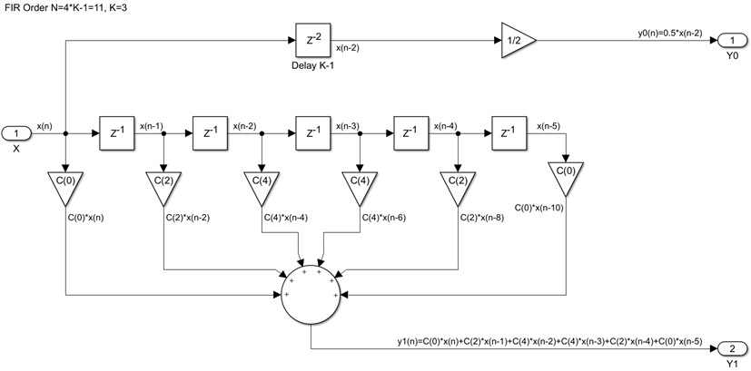
We can see that all the delays in the second branch are even, while the delay in the first branch is odd. Since all the odd input samples are zero, the final output adder is not required, since either one or the other of the two terms it is adding will always be zero. The first branch will actually produce all the even output samples and the second branch all the odd output samples and we can remove this output adder. There is also no need to insert zero samples in the input stream and this leads to replacing every two delays with a single one, running at the lower input rate:
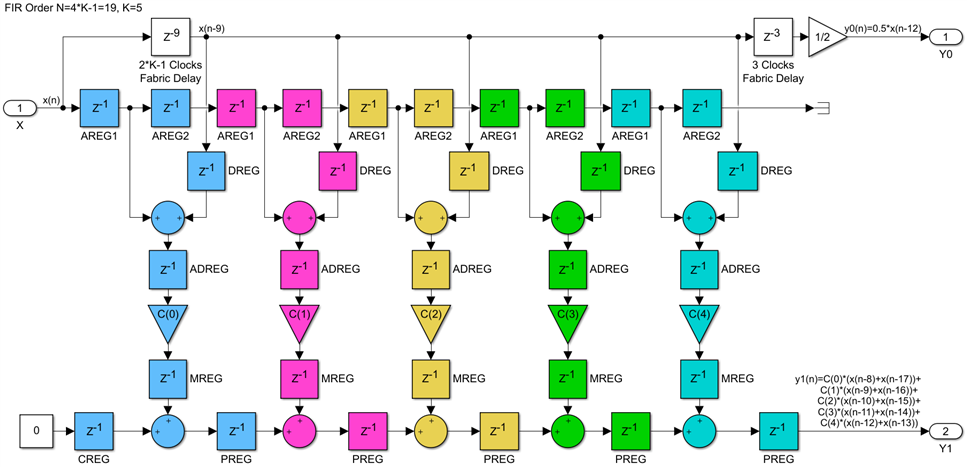
Compared with the previous filter, this one runs at the slower input rate, without the zero sample insertion. It accounts for the doubling of the output rate by producing two output samples for every input sample. The even output samples are simply delayed versions of the input samples and they account for the center tap of the prototype half-band FIR. The odd output samples are computed using an even-symmetric single rate FIR built with the remaining non-zero coefficients. Since we have already discussed in earlier posts how to implement efficiently even-symmetric single rate FIRs, we just reuse those results. Both direct and transpose implementations are possible. Here is how the direct implementation for a half-band interpolating FIR with a prototype filter of order N=19 would look like:
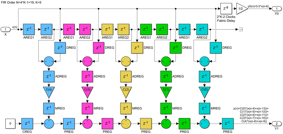
Registers, adders and multipliers that will map into the same DSP48s have similar color backgrounds, while everything with a white background is using fabric resources. A transpose implementation is very similar, note that the order of the coefficients is swapped:
As discussed previously, the transpose implementation has lower latency, which is constant and does not increase with the filter order but will not scale to any filter size. This limitation can be easily addressed with the use of extra pipeline registers, inserted every 20 taps or so.
The half-band interpolator is an important FIR building block. Cascades of such filters are routinely used to increase the sample rate of a signal by rates that are powers of 2. It is the most efficient way of achieving this operation. Compared with the original mathematical algorithm we used at the start of this post, these final FPGA hardware implementations are 8x times more efficient in terms of multiplications per output sample. A 2x factor is due to taking advantage of the prototype filter symmetry, another factor of 2x for not computing multiplications with coefficients that are zero, and another factor of 2x by not computing multiplications with input samples that are zero. Although the example prototype filter used above has an order N=19, only 5 DSP48s are used to compute every two output samples, or 2.5 multiplications per output sample.
In the next post we will look at the opposite operation, decimating or reducing the rate of an input signal by a factor of 2x, using a half-band FIR.
Back to the top: The Art of FPGA Design Season 2


Top Comments
-

DAB
-
Cancel
-
Vote Up
+1
Vote Down
-
-
Sign in to reply
-
More
-
Cancel
Comment-

DAB
-
Cancel
-
Vote Up
+1
Vote Down
-
-
Sign in to reply
-
More
-
Cancel
Children