


LWDF IIRs
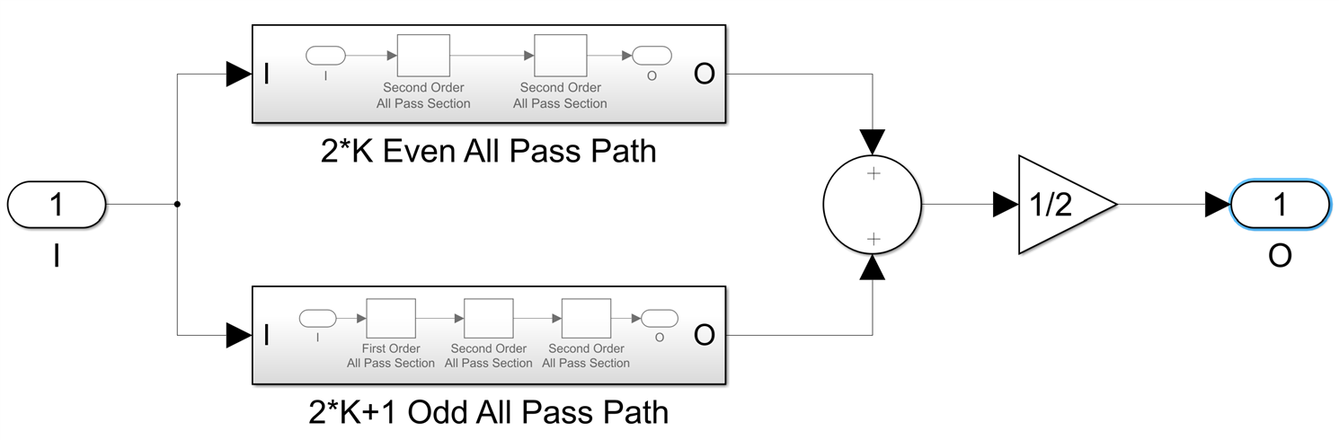
I am finally ready now to discuss the LWDF IIR filter architecture. In a few words, such a filter consists of two parallel all pass sections, which differ in order by 1, which means that one path is of odd order while the other one is even. The input data is applied to both paths and the output of the IIR filter is the sum of the outputs of the all pass sections divided by 2. If we denote the number of second order all pass sections in the even path by K, we have two cases, N=2*K+1:
and N=2*K-1:
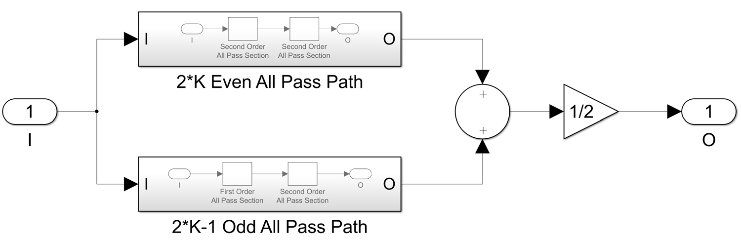
illustrated here for K=2, but K can be any value 1 or greater.
The order of the entire IIR filter N is the sum of the orders of the two paths, so N will always be odd, there are no even order LWDF filters. The magnitude of the filter transfer function is the cosine of half of the difference between the phases of the two paths. The phase and group delay of the IIR filter are the averages of the two paths phases respectively group delays and we have explicit formulas for all of these, which I derived in the previous blog post, so there are relatively simple formulas to calculate the magnitude, phase and group delay of any IIR filter with LWDF topology at any frequency f.
These two structures work as a low pass filter because the phase delay of an all pass cascade of order N always decreases from 0 at f=0 to -N*Pi at f/Fs=0.5, the Nyquist frequency. If designed properly, the two all pass branches will have similar phases in the pass band and add constructively (which is why dividing by 2 gives more or less the input signal), while in the stop band their phases have a difference of plus or minus Pi and will cancel each other. A bonus feature of the LWDF topology is that if you subtract the outputs of the two paths and divide by 2 you get the complementary high pass filter, essentially for free.
Since a first order all pass section requires one multiplier and a second order one needs two, the entire IIR of order N requires only N multiplications, compared to 2.5*N for a biquad cascade. In that sense, the LWDF IIR filter is more like an FIR of order N, which also needs N multiplications. As we will see later, the similarities do not stop there.
The big question now is how do you chose the all pass section coefficients to achieve a desired low pass transfer function for the entire filter - the filter synthesis problem. The bad news is that it is not a trivial task and a lot of math is involved. The good news is that this problem has been solved 40 years ago for four very common IIR filter types, Butterworth, Chebyshev I and II and Cauer( better known as Elliptic).
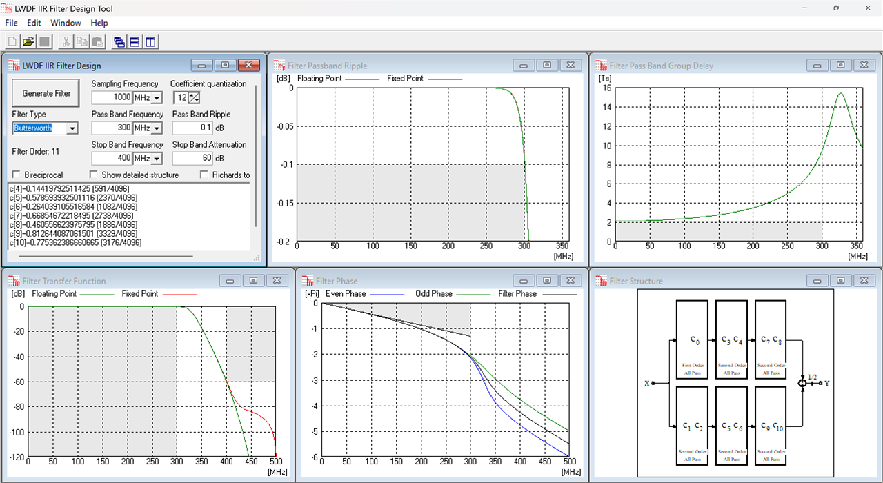
In general a low pass filter is specified by a number of parameters: the sampling frequency Fs, the pass band frequency f_p, the stop band frequency f_s, the pass band ripple a_p and the stop band attenuation a_s. I will illustrate the four types of IIR filters and their LWDF topology design using as an example Fs=1000MHz, f_p=300MHz, f_s=400MHz, a_p=0.1dB and a_s=60dB.
The Butterworth filter is maximally flat, both in the pass band and in the stop band and a filter of order N=11 is required to meet the specs:
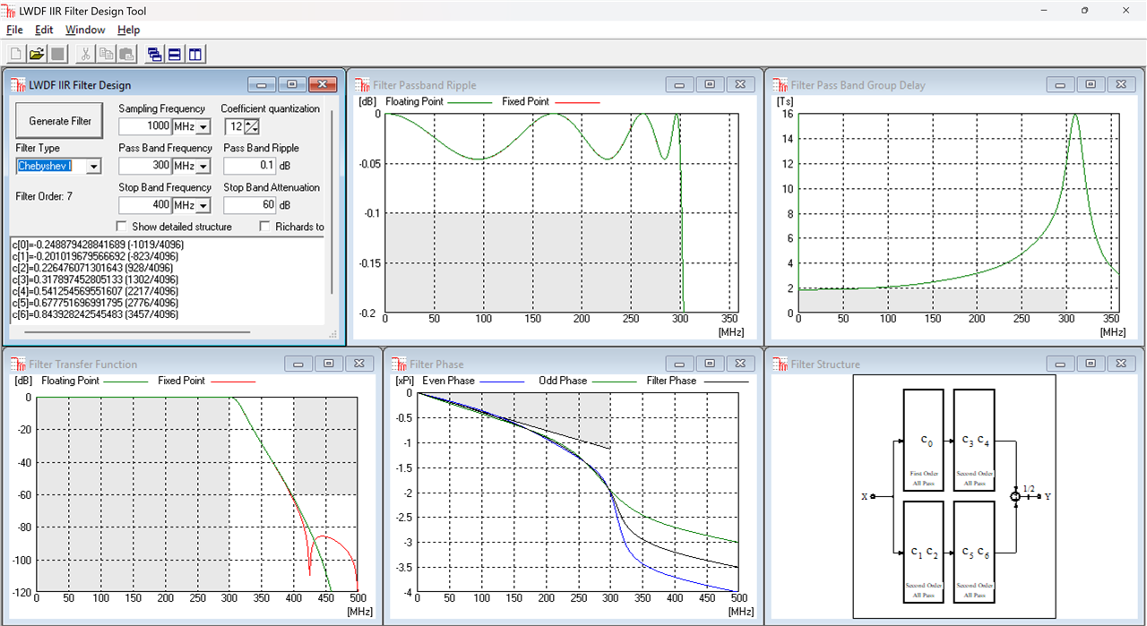
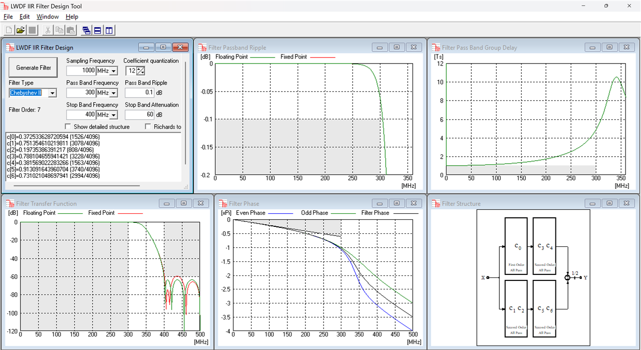
The Chebyshev I filter is equiripple in the pass band and maximally flat in the stop band, relaxing the pass band from maximally flat to equiripple means a filter of order N=7 is needed:
The Chebyshed II filter is the opposite, maximally flat pass band and equiripple stop band, same filter order N=7:
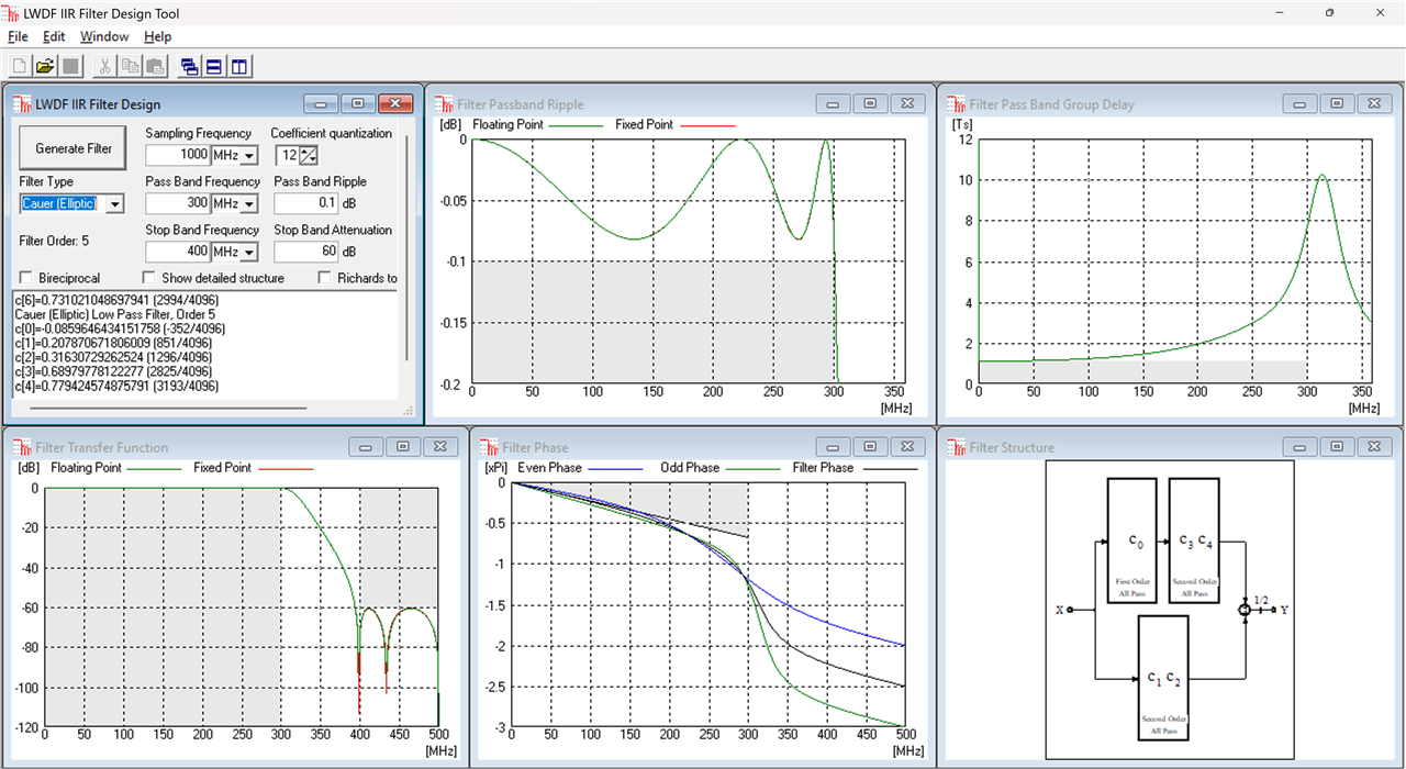
Finally, the Cauer or Elliptic design allows for equiripple in both the pass and stop bands and has the smallest order, N=5:
A further thing to notice is the very low coefficient sensitivity, all four filters basically meet the all the requirements with only 12 bits of coefficient precision. For comparison, here is an equivalent equiripple FIR designed with the Matlab fdatool with the same specs:
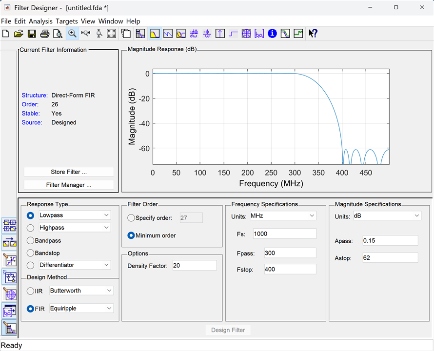
I had to tweak the specs a bit to achieve similar results but basically you need a filter of order N=27. The Elliptic IIR requires 5.4x less multiplications (to be fair 2.7x less if we take advantage of the FIR symmetry), the price being of course the lack of linear phase. These are very small filters, the larger the equivalent FIR order is, the larger the savings when using an IIR are. Savings factors of 10x or more for larger FIR filter orders are typical.
Another potential source of savings when using FIRs is the halfband architecture, if a particular type of transfer function, symmetric around the Fs/4 frequency point is acceptable, an FIR topology called half-band exists, see the previous Post 9. In this case half of the FIR coefficients are zero, except for the center tap coefficient which is always 0.5. While this will reduce the number of multipliers in such an FIR by a factor of 2x, a similar architecture called bireciprocal exists for the LWDF IIRs, where one coefficient of every second order all pass section, as well as the single order section coefficient are all zero. A bireciprocal LWDF filter of order N requires N/2 multiplications so the same savings as those provided by half-band FIRs do exist. This bireciprocal form exists for Butterworth and Elliptic filters, but not for the two Chebyshev forms.
Like I already mentioned, the problem of designing these four types of IIR transfer functions using the LWDF topology made out of first and second order all pass sections has been solved 40 years ago by Lajos Gazsi in an IEEE paper called Explicit Formulas for Lattice Wave Digital Filters. So the good news is designing these types of filters from specs is possible using a known algorithm. The bad news is that even after 40 years the paper is still behind a paywall. The four screenshots I used in this post are taken from a Windows program I wrote a long time ago which implements Gazsi's formulas.
In the next blog post I will discuss efficient ways of implementing these first and second order all pass sections, and as a consequence LWDF IIR filters in FPGAs, especially how to pipeline them for achieving best performance.
Back to the top: The Art of FPGA Design Season 2
