


Linear Phase IIR Filters? Part 1
I hope everybody can agree by now that IIR filters, especially in their LWDF form, are at least interesting and worth a look. I mean, an order of magnitude on average less resources compared with an equivalent FIR has to raise some eyebrows, right?
But the elephant in the room is linear phase, what good is a very efficient filter implementation if it doesn't have linear phase? And from a pure mathematical point of view, by definition no IIR filter can ever have linear phase. Because of poles or something like that.
But we are all engineers here and math is not the goal, just a mean to an end. The fact is we do not really need absolute linear phase, especially not in the stop band of a filter for example, who cares about the phase of nothing? If we can get close enough, especially as close as we possibly want, that's good enough.
There will always be other sources of imprecision in the system, like finite precision arithmetic, noise from rounding or quantization or even noise as part of the input signal and there is no point in asking for absolute linear phase if any errors produced by close enough linear phase are smaller than these other things. As long as we can get as close to linear phase as we want, "almost" linear phase IIR filters are as good as any true linear phase FIRs from this point of view.
So now the question becomes this: how can we achieve "almost" linear phase IIR filters and what will be the cost for that, because nothing in life is free. I alluded earlier that there are at least three different ways of achieving this goal that I know of, so here is the first one.
Forward-Backward Filters
There is a bit of complex math at play here but with some handwaving the main idea is this: if you have a non-linear phase filter and pass the input signal through it twice, first normally forward in time and then backwards or time reversed, the resultant transfer function has a magnitude that is the square of the magnitude of the initial filter and its phase is linear. The passband ripple and stop band attenuation will be double when expressed in dB, while the passband and stop band frequencies do not change. But we can design for that, the building block filter is the square root of the final desired filter, and this is actually an easier filter, usually about half the order of the equivalent filter.
This is a good thing, there is almost no penalty in terms of filter order, we do need two filters instead of one but their order is half. There is however a small problem, both the input signal and the filter's impulse response are infinite in time, that's what the first I in IIR stands for after all. And we need to compute a convolution between the signal and the filter impulse response and at least one of them needs to be time flipped and they are both infinite.
The key fact here is the realization that the IIR filter response is infinite only in theory, in practice sooner rather than later the response will decay beyond our ability to represent very small numbers with finite precision arithmetic. What mathematicians call real numbers exist only in their abstract world, you cannot represent them in a computer or FPGA. So we can always truncate the impulse response and now that it is finite, we have something we can work with.
Now I can go again into the weeds with the math, or I can use a pretty picture to convey the idea, based on comments on previous posts I think I know which way to go, so here it is, how to make any non-linearphase IIR linear using the forward-backward filtering technique, the overlap and add version:
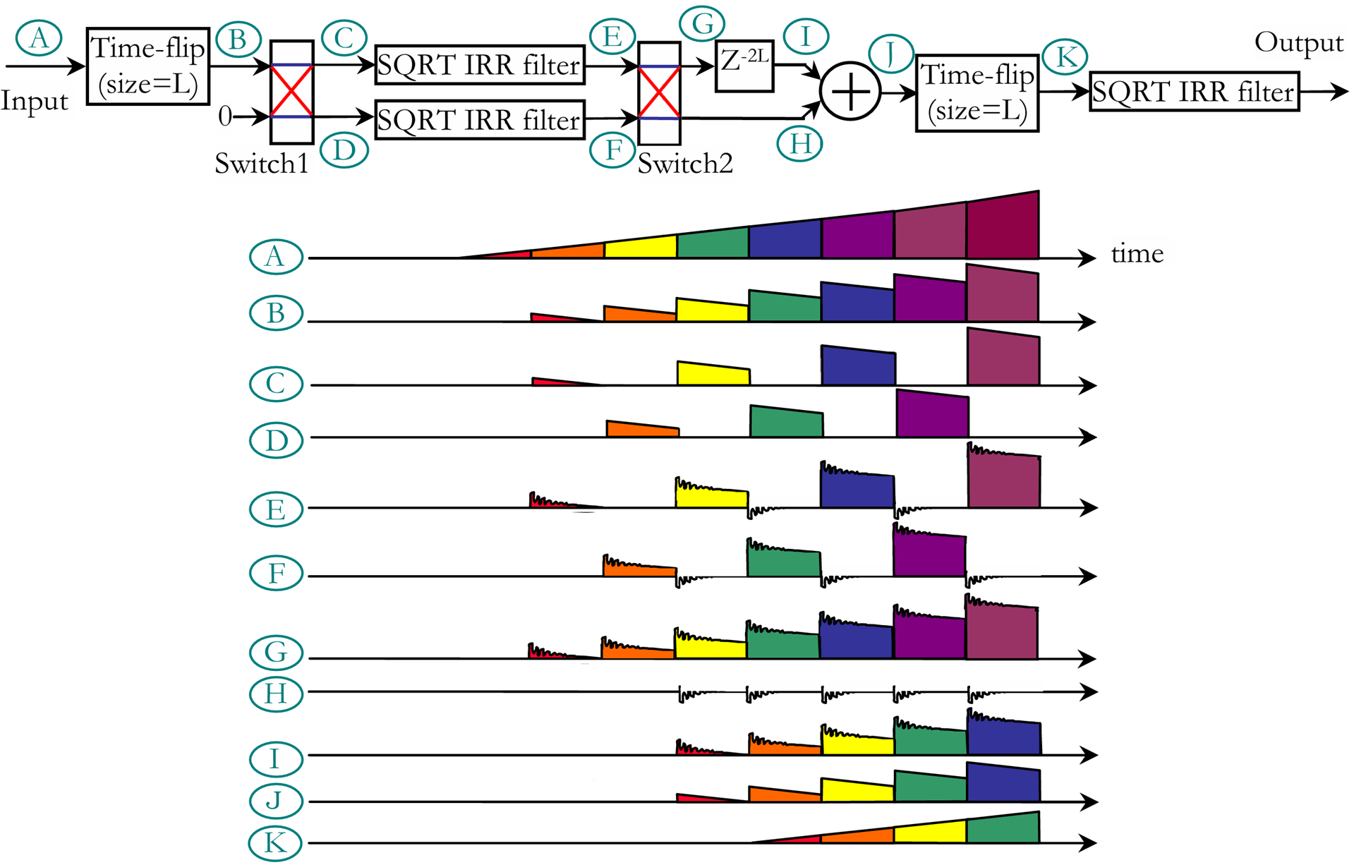
OK, the design first. It turns out we need three instances of our square root IIR filter, not just two, but since each one is about half the size of the final desired filter, this should still be OK. The input data is chopped into blocks of size L, where L is a parameter of our choice. A good starting point is the order of the FIR equivalent implementation of our desired filter but we can play with that value if needed. There are two identical time flip blocks, they take the input samples, buffer L of them then output them in time flipped order. At first glance it looks like you have to use a ping-pong buffer technique, so 2*L memory locations to achieve that, but there is a simple design idea that does the time flip using a single port RAM of size L. There is also a delay of 2*L size so in total the memory requirement is 4*L. The last block, also used twice is a 2-way switch, it has two inputs and two outputs and data is passed either directly or swapped. This is done on a per block basis, the switch toggles every L samples, so even blocks pass unchanged, while odd blocks get swapped.
To explain how this works I use a ramp input signal, which has mainly low frequency components and it should pass through our low pass filter more or less unchanged. The input data A is chopped into blocks of size L which are colour coded so we can trace them as they propagate through the system. B is how the data looks after passing through the first time flip block. The first switch splits this into even and odd streams C and D. The second switch input is zero to fill the gaps for the missing blocks in the two parallel streams. At the two square root IIR filter outputs, E and F, we can see the ringing produced by the sharp step discontinuities in the input data, these are the things we need to get rid off. The length of the missing block gaps, L, must be large enough so that this ringing dies down below some acceptable level.
The second switch reassembles the blocks into a stream G where we have all the input blocks, time swapped and with ringing, and a second stream H containing only the ringing from the block gaps. Here is where the magic happens. If you delay the stream G by 2*L clocks and then add it with H all the ringing cancels out and we get J. All that remains to be done now is to time flip that into K, which is the input A ran through the square root IIR filter backwards and if you pass this through the final square root IIR forward we get our final filter output and everything is linear phase! "If it walks like a duck, swims like a duck, and quacks like a duck, then it probably is a duck", a linear phase FIR I mean.
So let's say we have a large FIR of order N, hundreds, maybe thousand of taps. Since we are talking linear phase here, the filter must be symmetric so its hardware cost is N/2 multiplications. We could implement an equivalent IIR filter, in terms of the amplitude of the transfer function, say a Cauer (Elliptic) one and it will be between 10x and 20x smaller, but very non-linear phase. Let's say its complexity is N/20. Instead we design a square root version of this filter, with an N/40 complexity and since we need three of these filters, 3*N/40 multipliers. Compared to the original FIR implementation we are still 7x better but with linear phase now!
We also need 4*L locations of memory, where L is on the order of N and we can have a trade-off between the amount of memory and the precision of the phase approximation by adjusting L up or down. Finally, we need two switches but these are negligible, each one composed of two 2:1 muxes. All in all, in terms of hardware resources, this "linear phase" IIR solution will be much better than any FIR of order N>50 or so.
Of course, there is no free lunch. What we gain in efficiency we pay in latency, this entire scheme has a latency of 4*L. For designs using an FIR of large enough order, where the extra latency does not matter but linear phase is essential this could be a very good replacement.
There is also an overlap and save version of this design:
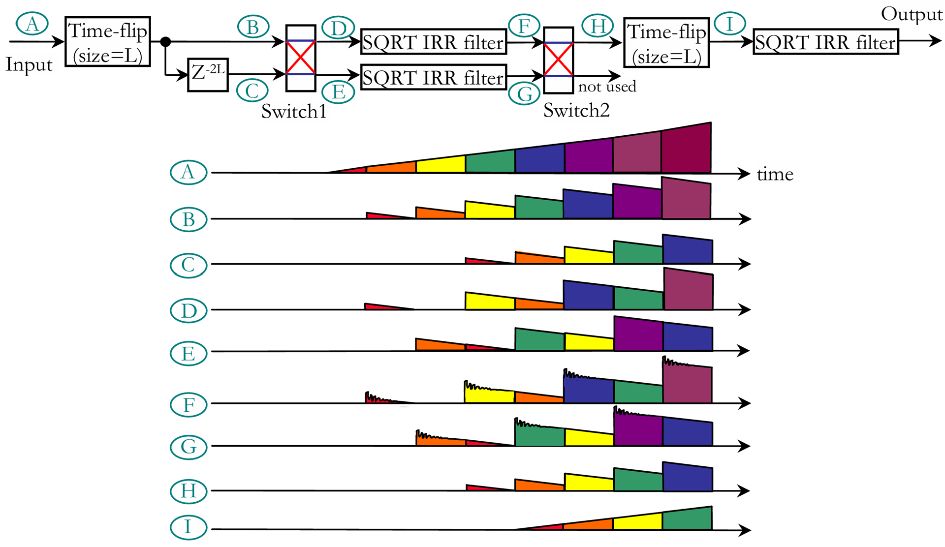
I will not go into the details but the basic idea is the same. This time pairs of consecutive L blocks pass through the first two filters and only the second block in each pair, the one with no ringing, is kept. This solution uses the same resources except that there is no adder and only three 2:1 muxes are needed, so it is slightly more efficient. The latency is also the same, 4*L.
I will end this long post with a design example using this technique. I will use the last filter specification from the previous post, F=1000MHz, f_p=245MHz, a_p=1mdB, f_s=250MHz, a_s=120dB. We already know that the equivalent FIR has order N=1229, using 615 multiplications, while a non-linear Elliptic IIR has order 23, with 23 multiplications so 26.7x smaller.
For this forward-backward design technique we will need an Elliptic square root IIR filter with these specifications: F=1000MHz, f_p=245MHz, a_p=0.5mdB, f_s=250MHz, a_s=60dB:
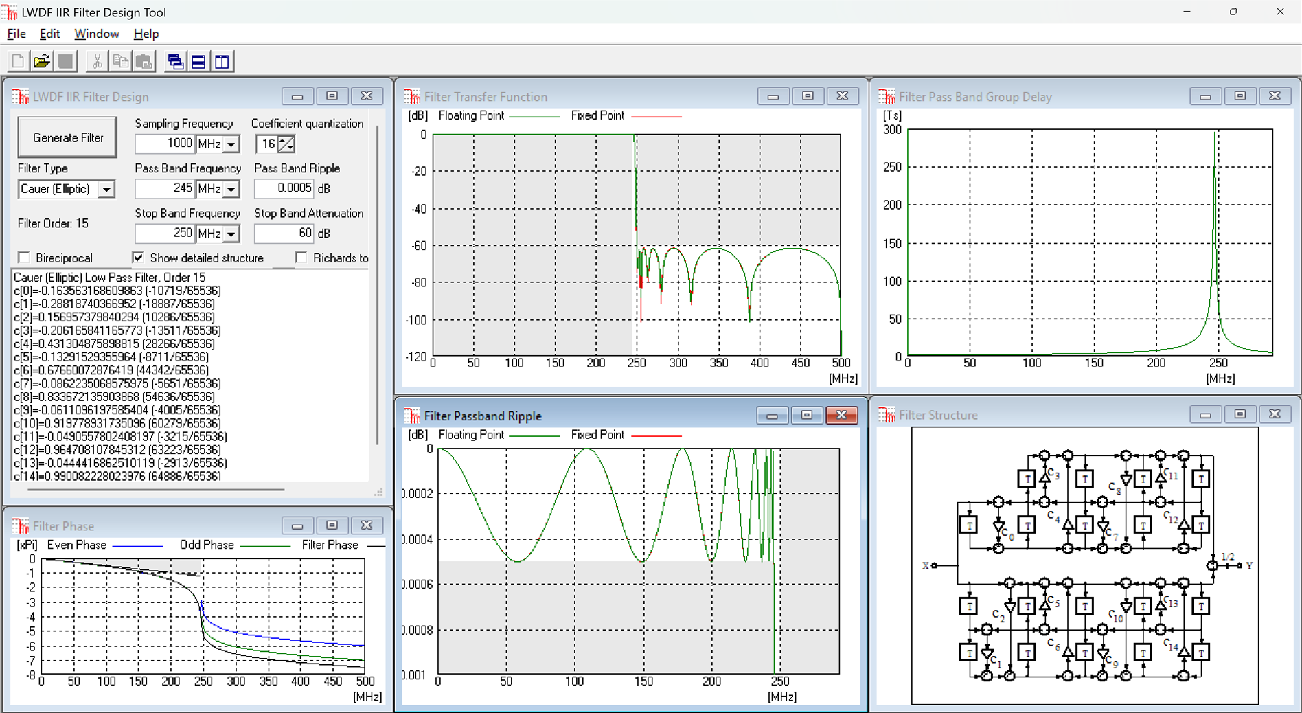
This IIR filter order is 15 and since we need three instances, that's 45 multipliers, which is still 13.7x better than the FIR!
Back to the top: The Art of FPGA Design Season 2
