


Introduction
This blog post provides details on how to build and execute the new 2020.2 design for the Ultra96-V2 development board with Dual-Camera Mezzanine.
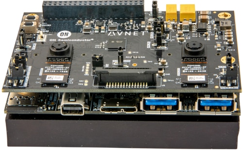
| {gallery} Ultra96-V2 Dual Camera Photos |
|---|
Ultra96-V2 with Dual Camera Mezzanine |
Ultra96-V2 with Dual Camera Mezzanine |
Dual Camera Mezzanine |


Design Overview
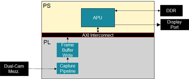
The following block diagram illustrates the 2020.2 version of the hardware design.
The following images capture the resource utilization of the design.


When compared to the previous version of the design 2020.1, the following changes have been made:
- removed the OSD core, including the entire live DisplayPort (DP) sub-system, which was determined to not be required
- modified the capture pipeline
- added a VPSS core for color space conversion
- added BGR format support to the frame buffer write core
- added of the AXI interrupt logic for use with Vitis
Supported Sensor Modules
The following sensor modules are supported by the linux-based 2020.2 design:
- AR0144 IAS Sensor Module
- part number : CAV10-000A
- datasheet : http://avnet.me/ias-ar0144-datasheet
- features :
- 1 Mpixel monochrome sensor
- global shutter
- AR1335 IAS Sensor Module
- part number : CAVBA-000A
- datasheet : http://avnet.me/ias-ar1335-datasheet
- features :
- 13 Mpixel (4K) color sensor
- rolling shutter
- auto-focus
Although the Dual Camera Mezzanine comes with two (2) AR0144 IAS sensor modules, it also supports a single AR1335 sensor module.
Capture Pipeline Overview
The linux-based 2020.2 design supports a dynamically configurable capture pipeline for the following three configurations:
- Dual AR0144 Sensors
- Single AR0144 Sensor
- Single AR1335 Sensor
The dual-camera mezzanine makes use of MIPI in order to connect the image cameras to the processing board.
The hardware design implemented in the programmable logic (PL) includes the following components:
- MIPI CSI-2 RX receiver IP core
- Image Pipeline : implemented with Color-Space-Conversion, and Scaler
- Frame Buffer Write : the DMA engine implementing writes to external DDR
Dual AR0144 Camera Pipeline
The following image illustrates the capture pipeline for the Dual AR0144 configuration.

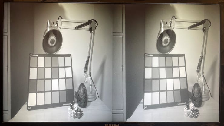
It is important to known that the AP1302 ISP receives the stereo images and generates a single side-by-side-image, as shown below:

Although the side-by-side image reflects the frontal view of the dual camera mezzanine, it is important to know that it contains:
- image from left (L) camera (SENSOR2) on right side
- image from right (R) camera (SENSOR1) on left side
This clarification is essential for any stereo processing that is attempted.
When in doubt, or to convince yourself, place your finger in front of one of the cameras and notice which side of the side-by-side image is blocked.
Single AR0144 Camera Pipeline
The following image illustrates the capture pipeline for the Single AR0144 configuration.

It is important to known that the single AR0144 configuration expects the sensor to be populated on the sensor1 header, as shown below:

Single AR1335 Camera Pipeline
The following image illustrates the capture pipeline for the Single AR1335 configuration.

It is important to known that the single AR1335 configuration expects the sensor to be populated on the sensor1 header, as shown below:
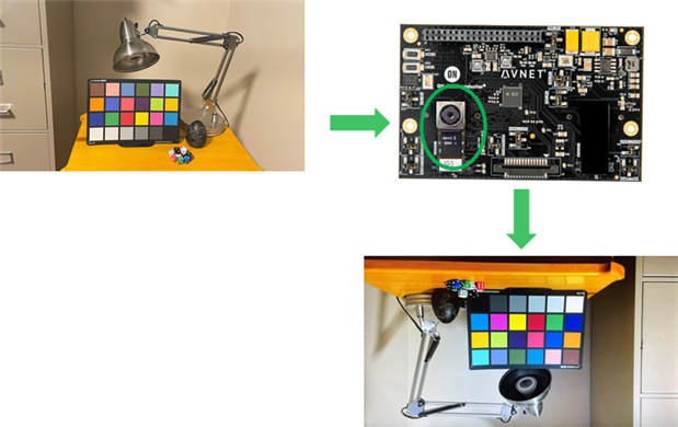
Also note that the upside-down image is not an error. For the AR1335 configuration, the image orientation is 180 degrees, with respect to the silkscreen logos.
According to the AR1335 IAS sensor module, this shouldn't be the case, so this may be a setting in the AR1335 or AP1302 firmware.
Rebuilding the Design
This section describes how to re-build the linux-based 2020.2 design.
This can be done on a linux machine, which has the Vitis 2020.2 and Petalinux 2020.2 tools correctly installed.
The following commands will clone the Avnet “bdf”, “hdl”, and “petalinux” repositories, all needed to re-build the linux-based design.
$ git clone https://github.com/Avnet/bdf
$ git clone –b 2020.2 https://github.com/Avnet/hdl
$ git clone –b 2020.2 https://github.com/Avnet/petalinux
To rebuild the linux-based design, use the following commands:
$ cd petalinux$ ./scripts/make_u96v2_sbc_dualcam.sh
This will launch the build for the hardware design and petalinux project. The build artifacts that are of interest are the following:
petalinux/projects/u96v2_sbc_dualcam_2020_2/images/linux/BOOT.BIN
petalinux/projects/u96v2_sbc_dualcam_2020_2/images/linux/boot.scr
petalinux/projects/u96v2_sbc_dualcam_2020_2/images/linux/image.ub
petalinux/projects/u96v2_sbc_dualcam_2020_2/images/linux/rootfs.tar.gz
These binaries can be programmed to a dual partition micro SD card, as follows:
- BOOT partition (FAT format)
- BOOT.BIN
- boot.scr
- image.ub
- ROOTFS partition (EXT4 format)
- contents of rootfs.tar.gz, extracted as root
Executing the Design with the Dual AR0144 configuration
After booting the board with the SD card, ensure that the /etc/init.d/load_default_camera_config script is specifying the following configuration
DAEMON=/usr/bin/load_camera_config
DAEMON_OPTS="ar0144_dual"
If this is not the case, edit the configuration, then reboot the design.
The X-windows desktop needs to be stopped in order to run the passthrough example, which is achieved with the following command:
$ /etc/init.d/xserver-nodm stopThe dual camera passthrough can be launched with the following command:
$ source run_1920_1080This script will perform the following steps:
- configure capture pipeline configuration using media-ctl utility
- configure monitor resolution using modetest utility
- launch gstreamer pipeline using gst-launch-1.0 utility
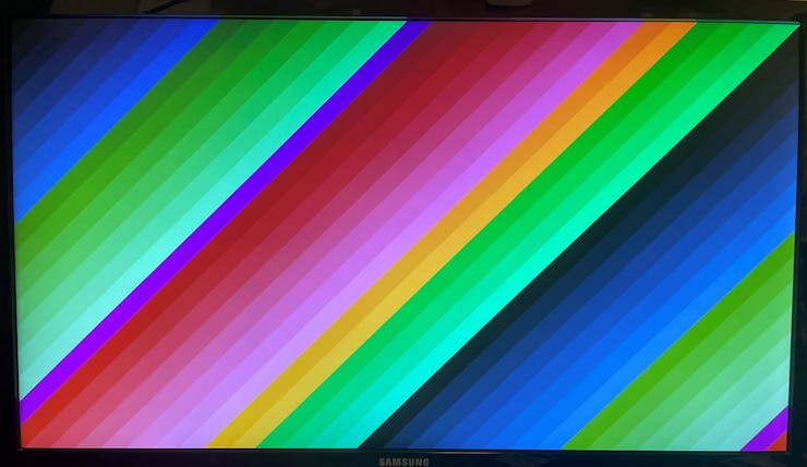
The following test pattern will be visible for ~1 sec (after execution of modetest).
Once the gstreamer pipeline is launched, the following side-by-side image will be visible on the monitor. Notice that the width is compressed by a factor of 2, which is only to make the dual images fit on the monitor.
The lens for each AR0144 can be manually rotated to adjust the focus, if required.
Side-by-Side configuration
As previously mentioned, the default side-by-side configuration defaults to the following:
- image from left (L) camera (SENSOR2) on right side
- image from right (R) camera (SENSOR1) on left side
$ i2cset -f -y 4 0x3c 0x10 0x0C 0x00 0x04 iThis will set value 0x0004 to register 0x100C (ORIENTATION) of I2C device 0x3C (AP1302) on I2C bus 4.
More specifically, this will set the following fields in the ORIENTATION register:
- [2] 3D_PATH = 1 : Secondary (SENSOR2 on left side)
- [1] FLIP_V = 0 : vertical flip off
- [0] FLIP_H = 0 : horizontal flip off
The ORIENTATION register can be read with the following commands:
$ i2cset -f -y 4 0x3c 0x10 0x0C
$ i2cget -f -y 4 0x3c
0x00
$ i2cget -f -y 4 0x3c
0x04
This will change the side-by-side configuration to the following:
- image from left (L) camera (SENSOR2) on left side
- image from right (R) camera (SENSOR1) on right side
Executing the Design with the Single AR1335 configuration
After booting the board with the SD card, ensure that the /etc/init.d/load_default_camera_config script is specifying the following configuration
DAEMON=/usr/bin/load_camera_config
DAEMON_OPTS="ar1335_single"
If this is not the case, edit the configuration, then reboot the design.
The X-windows desktop needs to be stopped in order to run the passthrough example, which is achieved with the following command:
$ /etc/init.d/xserver-nodm stop
In order to display the full resolution of the AR1335 sensor (3840x2160), the QoS configuration needs to be optimized for the DisplayPort (DP) monitor.
Otherwise, the DP controller will starve for bandwidth to external memory, and the image will contain glitches.
This is accomplished with the following command:
$ optimize_qos_for_dp
The 4K camera passthrough can be launched with the following command:
$ source run_3840_2160This script will perform the following steps:
- configure capture pipeline configuration using media-ctl utility
- configure monitor resolution using modetest utility
- launch gstreamer pipeline using gst-launch-1.0 utility
The following test pattern will be visible for ~1 sec (after execution of modetest).

Once the gstreamer pipeline is launched, the following image will be visible on the monitor (I have left the development kit upright to highlight the fact that the image is rotated 180 degrees).

Image Orientation
The image orientation is defined by the AP1302 ISP device, with the FLIP_V and FLIP_H settings of the ORIENTATION register, as described below:
- ...
- [1] FLIP_V = 0|1 : vertical flip
- [0] FLIP_H = 0|1 : horizontal flip
The default AP1302+1335 firmware has the FLIP_V and FLIP_H settings set to 1, which results in a 180 degree rotation of the image.
$ i2cset -f -y 4 0x3c 0x10 0x0C
$ i2cget -f -y 4 0x3c
0x00
$ i2cget -f -y 4 0x3c
0x03
The FLIP_V & FLIP_H fields (bits [1] and [0] of register ORIENTATION 0x100C) can be disabled with the i2cset utility:
$ i2cset -f -y 4 0x3c 0x10 0x0C 0x00 0x00 iThis will set value 0x0000 to register 0x100C (ORIENTATION) of I2C device 0x3C (AP1302) on I2C bus 4.
More specifically, this will set the following fields in the ORIENTATION register:
- ...
- [1] FLIP_V = 0 : vertical flip disabled
- [0] FLIP_H = 0 : horizontal flip disabled
The ORIENTATION register can be read with the following commands:
$ i2cset -f -y 4 0x3c 0x10 0x0C
$ i2cget -f -y 4 0x3c
0x00
$ i2cget -f -y 4 0x3c
0x00
Auto-Focus
There is no need to manually turn the lens for the AR1335 sensor module, since it implements Auto-Focus functionality.
The CAVBA-000A datasheet indicates the auto-focus is implemented with the following components:
- Lens Type : Largan 50013A7
- VCM Type : Jahwa QJ4C
- VCM Driver : DW9790A

In order to power the VCM device, the following jumper setting needs to be placed in the 1-2 position on the dual camera mezzanine.
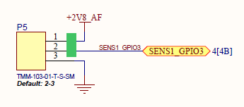
The Voice Coil Motor (VCM) is under control of the on-board AP1302 ISP device.
Although the AP1302 firmware has Auto-Focus "off" by default, it can be enabled by the user.
The Auto-Focus MODE (bits [3:0] of register AF_CTRL 0x5058) can be set to "Continuous Single Shot Mode" with the i2cset utility, as follows:
$ i2cset -f -y 4 0x3c 0x50 0x58 0x11 0x86 iThis will set value 0x1186 to register 0x5058 (AF_CTRL) of I2C device 0x3C (AP1302) on I2C bus 4.
More specifically, this will set the following fields in the AF_CTRL register:
- ...
- [13] MARKER_LEVEL = 0 : Auto-Focus Marker is displayed in basic mode (versus debug mode)
- [12] MARKER_EN = 1 : Auto-Focus Marker is displayed to indicate position (ROI) and status (red, green)
- ...
- [7] FF_ENABLE = 1 : Fast Focus algorithm enabled, stops scanning when sharpness falls sufficiently
- ...
- [3:0] MODE = 0x6 : Continuous Single Scan Mode, triggers auto-focus when significant scene change occurs
The AF_CTRL register can be read with the following commands:
$ i2cset -f -y 4 0x3c 0x50 0x58
$ i2cget -f -y 4 0x3c
0x11
$ i2cget -f -y 4 0x3c
0x86
Where to Buy the Hardware
The following links describe the hardware requirements needed to run this design.
Ultra96-V2
Buy Ultra96-V2Buy Ultra96-V2
or Ultra96-V2 I-grade
Buy Ultra96-V2 I-gradeBuy Ultra96-V2 I-grade
Ultra96-V2 4A Power Supply
Buy Ultra96-V2 4A Power SupplyBuy Ultra96-V2 4A Power Supply
Ultra96-V2 JTAG/UART Adapter
Buy Ultra96-V2 JTAG/UART AdapterBuy Ultra96-V2 JTAG/UART Adapter
96Boards onsemi Dual Camera Mezzanine
Buy 96Boards onsemi Dual Camera MezzanineBuy 96Boards onsemi Dual Camera Mezzanine
Going Further
A Vitis-AI 1.3 design has been built on top of this 2020.2 design, and is documented as a hackster.io project.

http://avnet.me/vitis-ai-1.3-dualcam
This hackster.io project includes the following additional content:
- instructions for building Vitis platform and Vitis-AI design
- pre-built SD card image for Vitis-AI enabled design
- python scripts for stereo processing (anaglyph, stereo face detection)
Conclusion
I hope this tutorial will help you get started quickly with the Ultra96-V2 and Dual-Camera Mezzanine, and inspire you to create innovative stereo applications.
If there is any other related content that you would like to see, please share your thoughts in the comments below.
Revision History
| Date | Description |
|---|---|
| 2021/09/01 | Initial Version. |
| 2021/09/03 | Add instructions on how to enable Auto-Focus for AR1335 sensor module. |
Top Comments