


Stereopsis is the inference of depth by comparing two images from slightly different perspectives. There are a number of local and global algorithms used to obtain a real time stereo depth map.
The computational requirements for stereo however are quite large. Before one delves into the implementation of stereo vision what is needed is a stereo camera setup!
This series will document how to build a stereo camera setup from scratch. The next step will then be to experiment with stereo algorithms.
In this project we will outline the design of a stereo camera platform for a ZYNQ FPGA SOC. The ZC702 development board will be used as the main SOC however the design can be easily ported to
any board with an FMC connector that uses the proper CMOS voltage levels for the camera. The first part of the project details the hardware design setup and Vivado FPGA design for a stereo platform setup.
Hardware
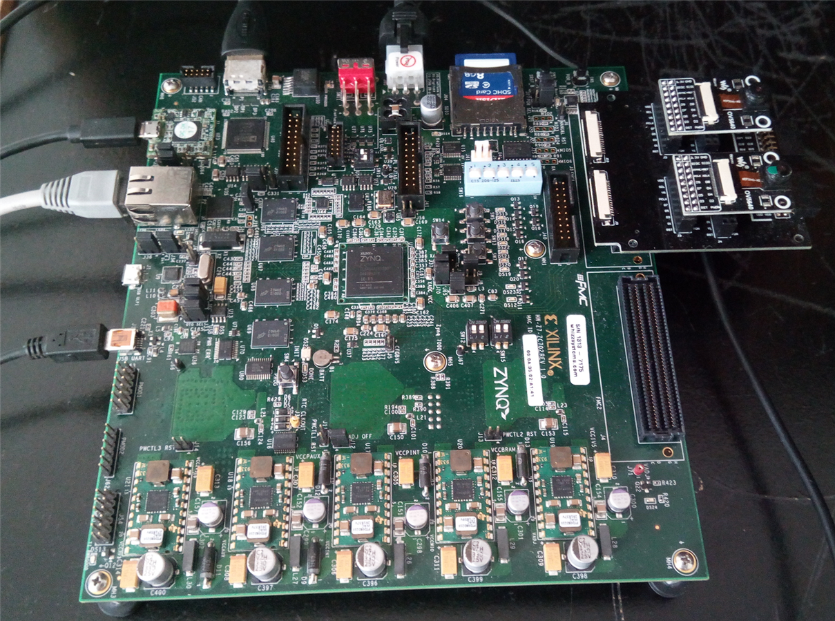
For this project DVP cameras were selected since they are easily obtainable. Another advantage is that one can find open configuration codes. On the other side the parallel interface requires 14 pins (16 if including the power pins) so
that amounts to 28 pins for a dual camera setup. This is where the FMC comes to play since it brings out a number of pins as differential pairs. Looking around for a FMC adapter card shows that there are very few that support a stereo setup.
In this case the design will be considerably simplified by keeping both images sources at the same baseline.
Each corresponding feature from the two cameras should be at the same level. This is called rectification. To simplify the rectification process the two cameras will be placed side by side.
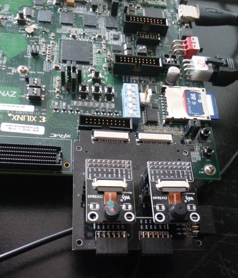
The Stereo FMC (schematics below) is a mezzanine card that allows one to use either DVP or MIPI-CSI cameras with any development board that is equipped with an FMC connector.
Camera configuration
The main advantages of this FMC are the fact that you can use different DVP cameras (OV7670, OV2640, OV5640) or even two Raspberry Pi V1 cameras with a MIPI-CSI interface.
As image sensors, the OV5640 DVP camera sensors were used. The main reason being the almost open source configuration codes found on the usual websites.
Since the cameras use the SCCB (a clone of I2C) for configuration , to configure both cameras, normally one would use a multiplexer. This FMC card however uses separate pins allocated for each camera.
Clock Synchronization
In a stereo setup, synchronization is another issue that shows up when dealing with the image sensors. Each sensor is fed with a master clock (XCLK). This clock decides the pixel output clock but normally for VGA resolution with these cameras it's around 24Mhz. To avoid additional synchronization issues on the FPGA the FMC schematics show that the XCLK clock is supplied to both cameras from a single pin.
Coincidentally, if this was not the case , that would add an extra step so one would have to use FIFOs and manually time the delay from one camera to the next.
Vivado Design
The main idea behind the Vivado design presented here is to test the camera setup.
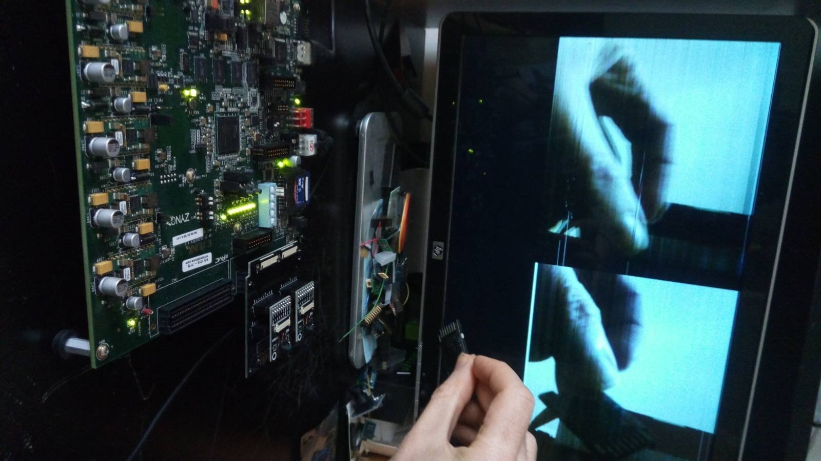
A couple of designs were implemented. The top level conceptual diagram is shown below. The camera data is sent to a VDMA and then piped to a video sink which can be a VGA , HDMI or even Displayport.

The Vivado IP integrator will be used to build a top level schematic with a video mixer. The output of the video mixer will be sent to the HDMI display.

A number of video blocks from the Vivado library are used as shown below. The version above uses the FMC dual PMOD to connect to a monitor. The version below uses the onboard HDMI codec.
A frame capture IP for each of the OV5640 cameras was used. This IP converts the parallel bus data to an AXI4-Stream protocol data stream. Both data streams from each camera go to a video mixer IP which takes two RGB streams and send them to a VDMA (Video DMA)
The VDMA copies the data to SDRAM and from there it's read back and sent as an AXI4-Stream to the HDMI video encoder or the FMC VGA PMOD connector.
The video output was configured with a 720p resolution in order to fit two VGA frames side by side.

Vitis SDK design
The design was tested using the bare-metal SDK, implemented in Vitis.
The main steps of the firmware are as follows:
1. First the GPIO peripherals are initialized. The cameras and mixer need an external reset.
2. Second , the I2C peripheral for each camera is initialized. In this design both PS I2C busses are used.
3. The external HDMI decoder onboard the ZC702 is then initialized.
4. There are 3 video sources in this setup. The TPG which is used as a canvas for the master layer and the two camera sources.
The TPG is configured first with a 1280p resolution. Next the two cameras are initialized and configured for RGB565 pixel format.
5. The VDMA is configured next. Since the pixels are resized to match with the AXIS stream format of the Video mixer, the VDMA must be configured to use 3 pixels per byte.
6. Since the color space of the mixer is in RGB format and the color space of the HDMI video mixer is in YUV422 format , a color space conversion followed by a chroma re sampling needs to be implemented.
The chroma-resampler IP requires a license however.
Some issues that were encountered due to SDK bugs with the mixer core. Specifically in streaming mode one has to edit the BSP library so that the full window resolution of each layer can be used.
In the second part the data from each camera will be piped to a stereo IP core in order to obtain a disparity (depth) map. The ZC702 does not have enough on-chip memory to implement a VGA resolution disparity map so the design can be ported to a Ultrascale+ board. Next will try to port this design to an Ultrazed board however the FMC on this board are routed to a port that is hardwired to operate at 1.8V. This would require some hacking of the camera sensors to operate at voltage levels with the same stereo FMC card. The solution would be to use a Ultrascale+ board with a programmable VADJ port and an IIC dongle such as ZC102 or ZC104.
Video Mixer IP issue
The video mixer used to place both camera images side by side has a bug since version 3.0 The IP currently used sits at version 5.
Edit xv_mixl2.c
  WinResInRange = ((Win->Width  > (XVMIX_MIN_STRM_WIDTH-1))  &&
                          (Win->Height > (XVMIX_MIN_STRM_HEIGHT-1)) &&
                          (Win->Width  <= MixPtr->Config.LayerMaxWidth[LayerId-1]) &&
                          (Win->Height <= MixPtr->Config.MaxHeight));
Each camera operates correctly when a switch is used but seem to loose sync when going through the mixer.
Next step in this series will be to port this design to PYNQ and use a stereo IP to implement a disparity map.
Code repo
For further details and code refer to the Hackster project:
https://www.hackster.io/dhq/fpga-stereo-camera-setup-part-i-a5f6fd
Top Comments