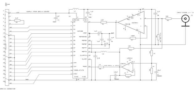
Have some of you an example "How to Connect an parallel ADC to the Lattice XP2 Brevia Dev Kit"?
It could be parallel ADC 10-16 bit, 20 MSPS or higher.
Thanks in advance!
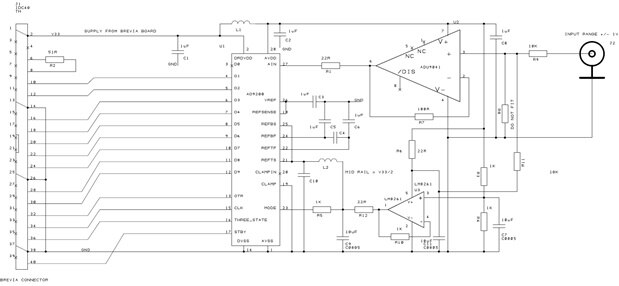
Have some of you an example "How to Connect an parallel ADC to the Lattice XP2 Brevia Dev Kit"?
It could be parallel ADC 10-16 bit, 20 MSPS or higher.
Thanks in advance!