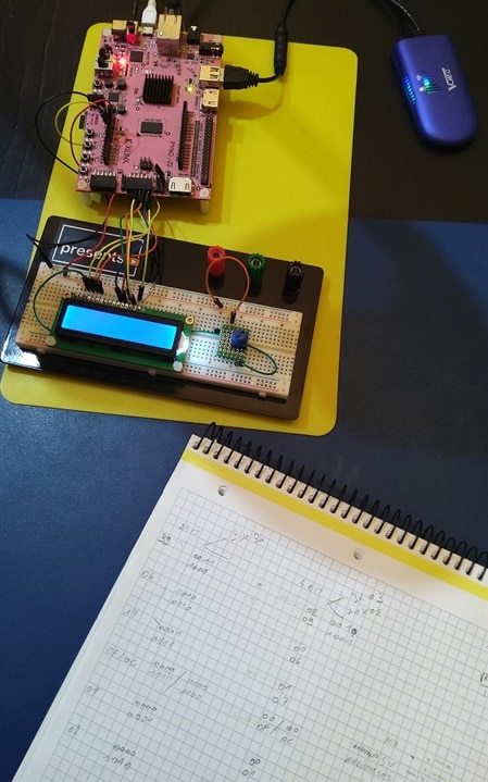
I'm going to try out a VHDL driver for the Hitachi HD44780 LCD driver.
I've ported it for several microcontrollers (TI Hercules, Maxim MAX32660) and a Linux device in the past.
I was going to write a VHDL driver, but found a few potential candidates online. I'm going to try Daniel Kampert's HD44780 LCD-Interface.
Current status:
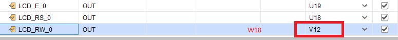
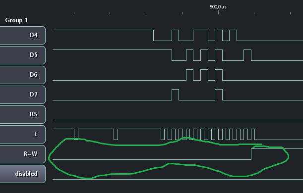
- VHDL code analysed
- Block diagram made: