element14 Community
element14 Community
    Register Log In
  • Site
  • Search
  • Log In Register
  • Community Hub
    Community Hub
    • What's New on element14
    • Feedback and Support
    • Benefits of Membership
    • Personal Blogs
    • Members Area
    • Achievement Levels
  • Learn
    Learn
    • Ask an Expert
    • eBooks
    • element14 presents
    • Learning Center
    • Tech Spotlight
    • STEM Academy
    • Webinars, Training and Events
    • Learning Groups
  • Technologies
    Technologies
    • 3D Printing
    • FPGA
    • Industrial Automation
    • Internet of Things
    • Power & Energy
    • Sensors
    • Technology Groups
  • Challenges & Projects
    Challenges & Projects
    • Design Challenges
    • element14 presents Projects
    • Project14
    • Arduino Projects
    • Raspberry Pi Projects
    • Project Groups
  • Products
    Products
    • Arduino
    • Avnet Boards Community
    • Dev Tools
    • Manufacturers
    • Multicomp Pro
    • Product Groups
    • Raspberry Pi
    • RoadTests & Reviews
  • Store
    Store
    • Visit Your Store
    • Choose another store...
      • Europe
      •  Austria (German)
      •  Belgium (Dutch, French)
      •  Bulgaria (Bulgarian)
      •  Czech Republic (Czech)
      •  Denmark (Danish)
      •  Estonia (Estonian)
      •  Finland (Finnish)
      •  France (French)
      •  Germany (German)
      •  Hungary (Hungarian)
      •  Ireland
      •  Israel
      •  Italy (Italian)
      •  Latvia (Latvian)
      •  
      •  Lithuania (Lithuanian)
      •  Netherlands (Dutch)
      •  Norway (Norwegian)
      •  Poland (Polish)
      •  Portugal (Portuguese)
      •  Romania (Romanian)
      •  Russia (Russian)
      •  Slovakia (Slovak)
      •  Slovenia (Slovenian)
      •  Spain (Spanish)
      •  Sweden (Swedish)
      •  Switzerland(German, French)
      •  Turkey (Turkish)
      •  United Kingdom
      • Asia Pacific
      •  Australia
      •  China
      •  Hong Kong
      •  India
      •  Korea (Korean)
      •  Malaysia
      •  New Zealand
      •  Philippines
      •  Singapore
      •  Taiwan
      •  Thailand (Thai)
      • Americas
      •  Brazil (Portuguese)
      •  Canada
      •  Mexico (Spanish)
      •  United States
      Can't find the country/region you're looking for? Visit our export site or find a local distributor.
  • Translate
  • Profile
  • Settings
Embedded and Microcontrollers
  • Technologies
  • More
Embedded and Microcontrollers
Blog MAX32660 Evaluation Kit - part 6: Driver LIB for a 16 x 2 LCD
  • Blog
  • Forum
  • Documents
  • Quiz
  • Polls
  • Files
  • Members
  • Mentions
  • Sub-Groups
  • Tags
  • More
  • Cancel
  • New
Embedded and Microcontrollers requires membership for participation - click to join
  • Share
  • More
  • Cancel
Group Actions
  • Group RSS
  • More
  • Cancel
Engagement
  • Author Author: Jan Cumps
  • Date Created: 10 Feb 2019 6:13 PM Date Created
  • Views 935 views
  • Likes 8 likes
  • Comments 2 comments
  • RoadTest
  • lcd
  • 44780
  • hitachi
  • rt
  • max32660
  • maxim
Related
Recommended

MAX32660 Evaluation Kit - part 6: Driver LIB for a 16 x 2 LCD

Jan Cumps
Jan Cumps
10 Feb 2019

I did a road test of the  Ultra-Low Power Arm Cortex-M4 Darwin MCU EVM.

In this post: a driver for the common Hitachy type LCD displays that you find everywhere.

image


The Display and Driver


In many automates you find these blue or green character displays. Typically 16 characters and two rows, but they come in different sizes.

Most of them have a Hitachi 44780 compatible driver. The Arduino LCD library can talk to them.

I've ported that driver a few times before, to another microcontroller and for the Siemens IOT2000 platform (Intel based linux single board computer).

I've ported it to the MAX32660 today (I expect it to work for other controllers from that family that use the same hardware API).

Library and example project are attached to this blog.


It requires 6 GPIO pins and an external 5V supply for the display.

On the display that I tested, I had to set the GPIO voltage of the MAX32660 to 3.3 V.

When in 1.8 V mode, the logic high wasn't detected by the display driver.

Not surprisingly. The specs says it recognises 2.7 V as high.


I've ported the main API functions:


void lcdInit(const gpio_cfg_t *rs, const gpio_cfg_t *enable, const gpio_cfg_t *d0,
  const gpio_cfg_t *d1, const gpio_cfg_t *d2,
  const gpio_cfg_t *d3);
void lcdBegin(uint32_t cols, uint32_t lines, uint32_t dotsize);
void lcdSetCursor(uint32_t col, uint32_t row);
void lcdPrint(const char *str);


The lcdInit() function takes 6 parameters, and those are the 6 pins needed to drive the screen.

The only thing happening in this function is binding the pins to their function, and initialising the control pins.

The data pins are bound when they are used.


I've tried to stay as true as possible to MAXIM's API. I used their gpio_cfg_t structure to set the pin attributes:


/**
 * Structure type for configuring a GPIO port.
 */
typedef struct {
    uint32_t port;          /**< Index of GPIO port */
    uint32_t mask;          /**< Pin mask (multiple pins may be set) */
    gpio_func_t func;       /**< Function type */
    gpio_pad_t pad;         /**< Pad type */
} gpio_cfg_t;


I've used the following pin assignment:

image

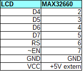
This results into this setup code:


gpio_cfg_t rs = {PORT_0, PIN_6, GPIO_FUNC_OUT, GPIO_PAD_NONE};
gpio_cfg_t enable = {PORT_0, PIN_7, GPIO_FUNC_OUT, GPIO_PAD_NONE};
gpio_cfg_t d0 = {PORT_0, PIN_2, GPIO_FUNC_OUT, GPIO_PAD_NONE};
gpio_cfg_t d1 = {PORT_0, PIN_3, GPIO_FUNC_OUT, GPIO_PAD_NONE};
gpio_cfg_t d2 = {PORT_0, PIN_4, GPIO_FUNC_OUT, GPIO_PAD_NONE};
gpio_cfg_t d3 = {PORT_0, PIN_5, GPIO_FUNC_OUT, GPIO_PAD_NONE};

lcdInit(&rs, &enable, &d0, &d1, &d2, &d3);


The next step is to start up the display:


lcdBegin(16,2, 0);


From then on, you can start sending commands.


const char sLine0[] =  "MAXIM MAX32660  \0";
const char sLine1[] =  "Hello, world!   \0";
lcdSetCursor(0, 0);            // move to the beginning of the first line
lcdPrint(sLine0);
lcdSetCursor(0, 1);            // move to the beginning of the second line
lcdPrint(sLine1);


Improvements


The MAX32660 has a PWM enabled pin, P0_3. I'm using it here for the data line d1, but if you move that to one of the other free gpio pins, you can dim the backlight from firmware.


I've made a naive loop for the microsecond timer. It's depending on the clock frequency


void lcdDelayMicroSeconds(uint32_t us) {

    /* Demonstrates the TMR driver delay */
    //    TMR_Delay(MXC_TMR0, USEC(us), NULL); // todo check if this is µsec or msec
    uint32_t i = 0;
    for( i=0; i < us * 4; i++) {
        asm(" nop");
    }
}


If you uncomment line 4 and comment line 5 -> 8, the controller uses one of the internal timers.

(It's timer 0. If you want to use PWM for the dimmer, then use one of the two other timers).


The data pins are configured at each data exchange. Not needed. You can configure them in either IcdInit() or lcdBegin().


I've made a _GPIO_OutPut() function for debug purposes.

If you plan to use the library and don't like this, just replace any call from _GPIO_OutPut() to GPIO_OutPut().

That will call the default Maxim function.

You can also use the macros from michaelkellett.


I haven't ported the full Arduino API. But all low level functions are available.

If you need something I haven't ported, just copy from the Arduino lib. The rework should be low.


For completeness: the capture of the startup sequence:
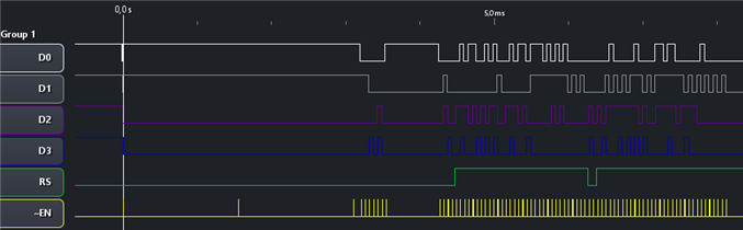
 

image


Enjoy!


part 1: IDE install and Build First Example
part 2: Mod the PCB for Power Measurement
part 3: Power Measurement
part 4a: Low Power Sensor design - Barometer Hardware
part 4b: Low Power Sensor design - Barometer i2c and Init
part 4c: Low Power Sensor design - Barometer, Not Yet Power Optimised
part 5: FreeRTOS Example
side note A: C++ Eclipse Project
side note B: Create a Release Configuration
part 6: Driver LIB for a 16 x 2 LCD
Attachments:
hitachi_lcd.zip
  • Sign in to reply

Top Comments

  • clem57
    clem57 over 5 years ago +1
    Nice demo of the LCD screen. Thanks Jan Cumps for a good write up.
  • clem57
    clem57 over 5 years ago

    Nice demo of the LCD screen. Thanks Jan Cumps for a good write up.

    • Cancel
    • Vote Up +1 Vote Down
    • Sign in to reply
    • More
    • Cancel
  • michaelkellett
    michaelkellett over 6 years ago

    Useful stuff, thanks for sharing.


    MK

    • Cancel
    • Vote Up 0 Vote Down
    • Sign in to reply
    • More
    • Cancel
element14 Community

element14 is the first online community specifically for engineers. Connect with your peers and get expert answers to your questions.

  • Members
  • Learn
  • Technologies
  • Challenges & Projects
  • Products
  • Store
  • About Us
  • Feedback & Support
  • FAQs
  • Terms of Use
  • Privacy Policy
  • Legal and Copyright Notices
  • Sitemap
  • Cookies

An Avnet Company © 2025 Premier Farnell Limited. All Rights Reserved.

Premier Farnell Ltd, registered in England and Wales (no 00876412), registered office: Farnell House, Forge Lane, Leeds LS12 2NE.

ICP 备案号 10220084.

Follow element14

  • X
  • Facebook
  • linkedin
  • YouTube