element14 Community
element14 Community
    Register Log In
  • Site
  • Search
  • Log In Register
  • About Us
  • Community Hub
    Community Hub
    • What's New on element14
    • Feedback and Support
    • Benefits of Membership
    • Personal Blogs
    • Members Area
    • Achievement Levels
  • Learn
    Learn
    • Ask an Expert
    • eBooks
    • element14 presents
    • Learning Center
    • Tech Spotlight
    • STEM Academy
    • Webinars, Training and Events
    • Learning Groups
  • Technologies
    Technologies
    • 3D Printing
    • FPGA
    • Industrial Automation
    • Internet of Things
    • Power & Energy
    • Sensors
    • Technology Groups
  • Challenges & Projects
    Challenges & Projects
    • Design Challenges
    • element14 presents Projects
    • Project14
    • Arduino Projects
    • Raspberry Pi Projects
    • Project Groups
  • Products
    Products
    • Arduino
    • Avnet Boards Community
    • Dev Tools
    • Manufacturers
    • Multicomp Pro
    • Product Groups
    • Raspberry Pi
    • RoadTests & Reviews
  • Store
    Store
    • Visit Your Store
    • Choose another store...
      • Europe
      •  Austria (German)
      •  Belgium (Dutch, French)
      •  Bulgaria (Bulgarian)
      •  Czech Republic (Czech)
      •  Denmark (Danish)
      •  Estonia (Estonian)
      •  Finland (Finnish)
      •  France (French)
      •  Germany (German)
      •  Hungary (Hungarian)
      •  Ireland
      •  Israel
      •  Italy (Italian)
      •  Latvia (Latvian)
      •  
      •  Lithuania (Lithuanian)
      •  Netherlands (Dutch)
      •  Norway (Norwegian)
      •  Poland (Polish)
      •  Portugal (Portuguese)
      •  Romania (Romanian)
      •  Russia (Russian)
      •  Slovakia (Slovak)
      •  Slovenia (Slovenian)
      •  Spain (Spanish)
      •  Sweden (Swedish)
      •  Switzerland(German, French)
      •  Turkey (Turkish)
      •  United Kingdom
      • Asia Pacific
      •  Australia
      •  China
      •  Hong Kong
      •  India
      •  Korea (Korean)
      •  Malaysia
      •  New Zealand
      •  Philippines
      •  Singapore
      •  Taiwan
      •  Thailand (Thai)
      • Americas
      •  Brazil (Portuguese)
      •  Canada
      •  Mexico (Spanish)
      •  United States
      Can't find the country/region you're looking for? Visit our export site or find a local distributor.
  • Translate
  • Profile
  • Settings
Internet of Things
  • Technologies
  • More
Internet of Things
Blog IoT Alarm Clock - Part 2
  • Blog
  • Forum
  • Documents
  • Quiz
  • Events
  • Polls
  • Members
  • Mentions
  • Sub-Groups
  • Tags
  • More
  • Cancel
  • New
Join Internet of Things to participate - click to join for free!
  • Share
  • More
  • Cancel
Group Actions
  • Group RSS
  • More
  • Cancel
Engagement
  • Author Author: fvan
  • Date Created: 13 May 2014 8:09 PM Date Created
  • Views 967 views
  • Likes 2 likes
  • Comments 3 comments
  • wolfson
  • clock
  • internet_of_things
  • raspberrypi
  • rpiexpert
  • iot
  • alarm
  • arduino
Related
Recommended

IoT Alarm Clock - Part 2

fvan
fvan
13 May 2014

Blog posts for this project:

  • IoT Alarm Clock - Part 1
  • IoT Alarm Clock - Part 2 (this post)
  • IoT Alarm Clock - Part 3


  • Pi-Lite
  • Arduino Micro
  • Buttons
  • Single power supply
  • Train API
  • Enclosure


This week's progress on the IoT Alarm Clock! Mainly soldering, but also some testing.


Pi-Lite


During boot, I noticed some messages and characters were being displayed on the Pi-Lite. To get rid of this, I followed the steps below.


Edit the inittab file and comment out the following line (completely at the end of the file):


sudo nano /etc/inittab

T0:23:respawn:/sbin/getty -L ttyAMA0 115200 vt100


Edit the cmdline.txt and remove the following part:


sudo nano /boot/cmdline.txt

console=ttyAMA0,115200 kgdboc=ttyAMA0,115200


The full explanation can be found on the Ciseco website:0: Setting up the Raspberry Pi to work with Ciseco hardware


Arduino Micro


As mentioned in the first part of this project, I'll be using an Arduino Micro to add a bunch of I/O to the Raspberry Pi.

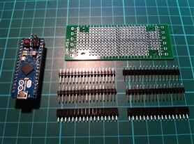
Using a small prototyping PCB and some male and female headers, I made a board to which:

  • the Arduino Micro can easily be plugged in or removed/replaced
  • buttons, LEDs, etc ... can easily be added and plugged in


As illustrated below, one row of male headers is connected to the Arduino's I/O on each side, and a second row of headers is connected to ground.

This allows me to plug in components which on one end will be connected to the Arduino I/O and on the other end to ground.

imageimageimage


I configured the Arduino to wait for interrupts and send a character over the Serial interface towards the Raspberry Pi via the USB connection.

The Raspberry Pi waits for data to come in, and once it does, triggers the correct action.


Arduino code:


void setup() {
  pinMode(0, INPUT_PULLUP);
  pinMode(1, INPUT_PULLUP);
  pinMode(2, INPUT_PULLUP);

  attachInterrupt(1, sendA, FALLING);
  attachInterrupt(2, sendB, FALLING);
  attachInterrupt(3, sendC, FALLING);

  Serial.begin(9600);
}

void loop() {

}

void sendA() {
  Serial.println('A');
}

void sendB() {
  Serial.println('B');
}

void sendC() {
  Serial.println('C');
}


Raspberry Pi code:


import serial
import os

ser = serial.Serial("/dev/ttyACM0",9600)

while(1):
        x = ser.read()
        if(x == 'A'):
                os.system("echo 'button 1' | sudo minicom -b 9600 -o -D /dev/ttyAMA0")
        elif(x == 'B'):
                os.system("echo 'button 2' | sudo minicom -b 9600 -o -D /dev/ttyAMA0")
        elif(x == 'C'):
                os.system("echo 'button 3' | sudo minicom -b 9600 -o -D /dev/ttyAMA0")
ser.close()


The result of this test:


You don't have permission to edit metadata of this video.
Edit media
x
image
Upload Preview
image


Buttons


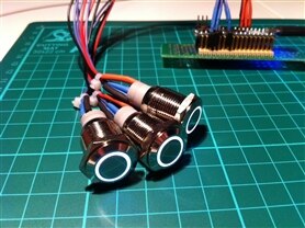
The breadboard pushbuttons worked fine, but I wanted something good looking, so I got some shiny illuminated pushbuttons.


I soldered wires for the pushbutton and for the integrated LED. Both are connected to the Arduino Micro, which can be used to react on button presses, but can also dynamically turn the button's LED on or off.

For example, by default all LEDs could be off until a button is pressed, in which case the LEDs will light up for 30 seconds before turning off again.

imageimageimage


Single power supply


Because I'm using the onboard amplifier of the Wolfson audio card, the card requires external power. Along with the Pi itself and the Pi-Lite, that makes a bunch of different components requiring a 5V power source.

I only want to use a single power supply to power my project, so I grabbed some cables, started cutting, stripping and soldering them into a master cable able to power all components.


Also, to make a more reliable connection to the Pi-Lite, I soldered some male header pins to which I can connect power and the serial pins of the Wolfson audio card.


imageimageimageimage


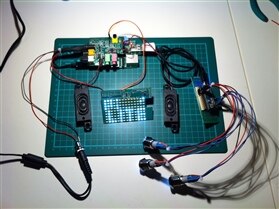
As you can see in the last picture, all components are now properly connected to the Pi.


Train API


With all the soldering and hardware setup pretty much done, it was time to move to the software part of this project.


To fetch the train data and be able to use it in the alarm clock, an API to query is most useful.

Luckily, there is a third party API available for belgian public transportation, called iRail. API documentation can be found here: API/APIv1 – Project iRail


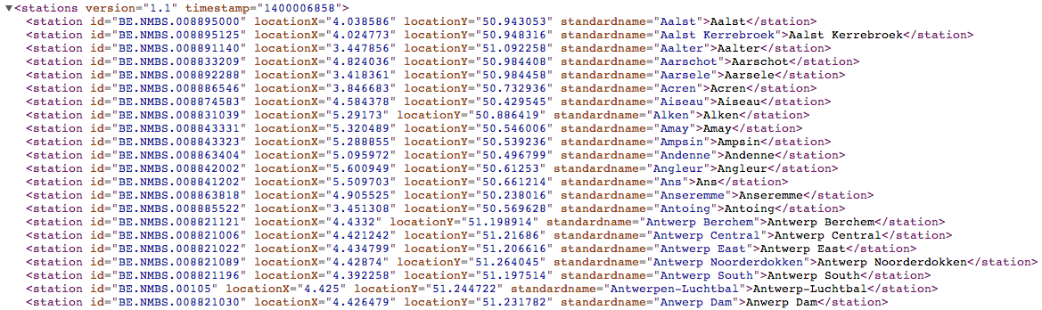
I've made some tests with calls that will be interesting for my application:


  • List stations: useful for defining from where to where you need to take the train
    • http://api.irail.be/stations/

image

  • List trains from station A to station B on a certain day with a certain departure or arrival time
    • http://api.irail.be/connections/?to=Brussels%20South&from=Lokeren&date=140514&time=0900&timeSel=arrive&typeOfTransport=train
    • From: Lokeren
    • To: Brussels South
    • On: May 14, 2014
    • Arrival: 09:00
    • Transport: Train

image


The second call returned 6 possible train connections between "Lokeren" and "Brussels South" for an arrival time around 09:00.

This data will need to be parsed carefully and the connection offering the most time to sleep in, while ensuring a timely arrival, should be selected.

In the exceptional case that all trains would be delayed, additional time to sleep in can be provided, while still picking the train connection with the best arrival time.


Enclosure


I started working on the enclosure in parallel. Not much done yet, but here's a sneak peek:


imageimageimage

image

  • Sign in to reply

Top Comments

  • fvan
    fvan over 11 years ago in reply to shabaz +1
    The LED display is driven via UART, so simple serial communication. I pipe the output of a script or command to minicom, resulting in that output appearing on the LED display, it's that simple "echo 'text…
  • fvan
    fvan over 11 years ago in reply to shabaz

    The LED display is driven via UART, so simple serial communication.


    I pipe the output of a script or command to minicom, resulting in that output appearing on the LED display, it's that simple image


    "echo 'text' | sudo minicom -b 9600 -o -D /dev/ttyAMA0"


    Documentation here: B040 - Pi-Lite User Guide (Pi-Lite)

    • Cancel
    • Vote Up +1 Vote Down
    • Sign in to reply
    • More
    • Cancel
  • shabaz
    shabaz over 11 years ago

    This is very cool!!

    Is the LED display SPI-driven, or some other convenient protocol? If so, it would be nice to use this for additional projects too.

    • Cancel
    • Vote Up 0 Vote Down
    • Sign in to reply
    • More
    • Cancel
  • fvan
    fvan over 11 years ago

    Part 3 is online! IoT Alarm Clock - Part 3

    • Cancel
    • Vote Up 0 Vote Down
    • Sign in to reply
    • More
    • Cancel
element14 Community

element14 is the first online community specifically for engineers. Connect with your peers and get expert answers to your questions.

  • Members
  • Learn
  • Technologies
  • Challenges & Projects
  • Products
  • Store
  • About Us
  • Feedback & Support
  • FAQs
  • Terms of Use
  • Privacy Policy
  • Legal and Copyright Notices
  • Sitemap
  • Cookies

An Avnet Company © 2025 Premier Farnell Limited. All Rights Reserved.

Premier Farnell Ltd, registered in England and Wales (no 00876412), registered office: Farnell House, Forge Lane, Leeds LS12 2NE.

ICP 备案号 10220084.

Follow element14

  • X
  • Facebook
  • linkedin
  • YouTube