element14 Community
element14 Community
    Register Log In
  • Site
  • Search
  • Log In Register
  • About Us
  • Community Hub
    Community Hub
    • What's New on element14
    • Feedback and Support
    • Benefits of Membership
    • Personal Blogs
    • Members Area
    • Achievement Levels
  • Learn
    Learn
    • Ask an Expert
    • eBooks
    • element14 presents
    • Learning Center
    • Tech Spotlight
    • STEM Academy
    • Webinars, Training and Events
    • Learning Groups
  • Technologies
    Technologies
    • 3D Printing
    • FPGA
    • Industrial Automation
    • Internet of Things
    • Power & Energy
    • Sensors
    • Technology Groups
  • Challenges & Projects
    Challenges & Projects
    • Design Challenges
    • element14 presents Projects
    • Project14
    • Arduino Projects
    • Raspberry Pi Projects
    • Project Groups
  • Products
    Products
    • Arduino
    • Avnet Boards Community
    • Dev Tools
    • Manufacturers
    • Multicomp Pro
    • Product Groups
    • Raspberry Pi
    • RoadTests & Reviews
  • Store
    Store
    • Visit Your Store
    • Choose another store...
      • Europe
      •  Austria (German)
      •  Belgium (Dutch, French)
      •  Bulgaria (Bulgarian)
      •  Czech Republic (Czech)
      •  Denmark (Danish)
      •  Estonia (Estonian)
      •  Finland (Finnish)
      •  France (French)
      •  Germany (German)
      •  Hungary (Hungarian)
      •  Ireland
      •  Israel
      •  Italy (Italian)
      •  Latvia (Latvian)
      •  
      •  Lithuania (Lithuanian)
      •  Netherlands (Dutch)
      •  Norway (Norwegian)
      •  Poland (Polish)
      •  Portugal (Portuguese)
      •  Romania (Romanian)
      •  Russia (Russian)
      •  Slovakia (Slovak)
      •  Slovenia (Slovenian)
      •  Spain (Spanish)
      •  Sweden (Swedish)
      •  Switzerland(German, French)
      •  Turkey (Turkish)
      •  United Kingdom
      • Asia Pacific
      •  Australia
      •  China
      •  Hong Kong
      •  India
      •  Korea (Korean)
      •  Malaysia
      •  New Zealand
      •  Philippines
      •  Singapore
      •  Taiwan
      •  Thailand (Thai)
      • Americas
      •  Brazil (Portuguese)
      •  Canada
      •  Mexico (Spanish)
      •  United States
      Can't find the country/region you're looking for? Visit our export site or find a local distributor.
  • Translate
  • Profile
  • Settings
Open Source Hardware
  • Technologies
  • More
Open Source Hardware
Blog Building Frank's Milliohm Meter
  • Blog
  • Forum
  • Documents
  • Events
  • Polls
  • Members
  • Mentions
  • Sub-Groups
  • Tags
  • More
  • Cancel
  • New
Join Open Source Hardware to participate - click to join for free!
  • Share
  • More
  • Cancel
Group Actions
  • Group RSS
  • More
  • Cancel
Engagement
  • Author Author: shabaz
  • Date Created: 2 Jan 2019 5:13 AM Date Created
  • Views 9049 views
  • Likes 12 likes
  • Comments 32 comments
  • milliohmmeter
  • 4 wire measurement
  • project14
  • milliohm_measurement
  • milliohm measurement
  • milliohm
  • milliohm meter
Related
Recommended

Building Frank's Milliohm Meter

shabaz
shabaz
2 Jan 2019

Introduction

This short blog post documents the specific component values and any mods done to the revision 1 PCB from  fmilburn  Working Prototype of a Kelvin (4-Wire) Milliohm Meter  Project14  Test Instrumentation entry!

It is a project intended to create a 4-wire measurement meter for 0-4 ohm and 0-40 ohm ranges, with sub-milliohm granularity.


It is a physically small test instrument, but works well! In very limited tests, the typical discrepancy between a calibrated commercial meter and this project was ballpark 0.1% although from that one can't promise that will definitely always be the case.

Lego blocks shown for size comparison:

image


I recorded a 10-min video with some basic test results:

You don't have permission to edit metadata of this video.
Edit media
x
image
Upload Preview
image


Schematic

I followed the schematic (Rev 1.0) in Frank's blog post here:

Working Prototype of a Kelvin (4-Wire) Milliohm Meter

Frank kindly sent me a spare PCB to construct it on.

It is better to wait for a Rev 2 board, but here's the values/mods on my PCB currently, I used these values for the tests:

image


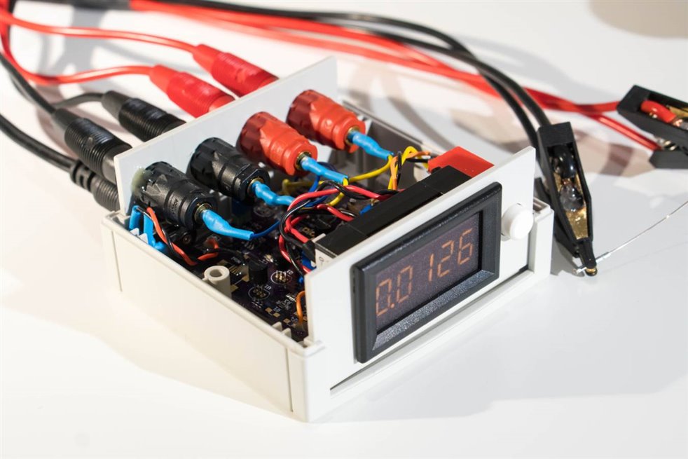
Enclosure and Assembly

The Bopla enclosureBopla enclosure has two end panels, these were cut/filed. The body of the case needed no modifications, except for trimming some tabs slightly, which support the end panels, but are unnecessary. They were trimmed by scoring and snapping off with pliers (it is soft ABS plastic), so that the panel meter and banana sockets could fit:

image

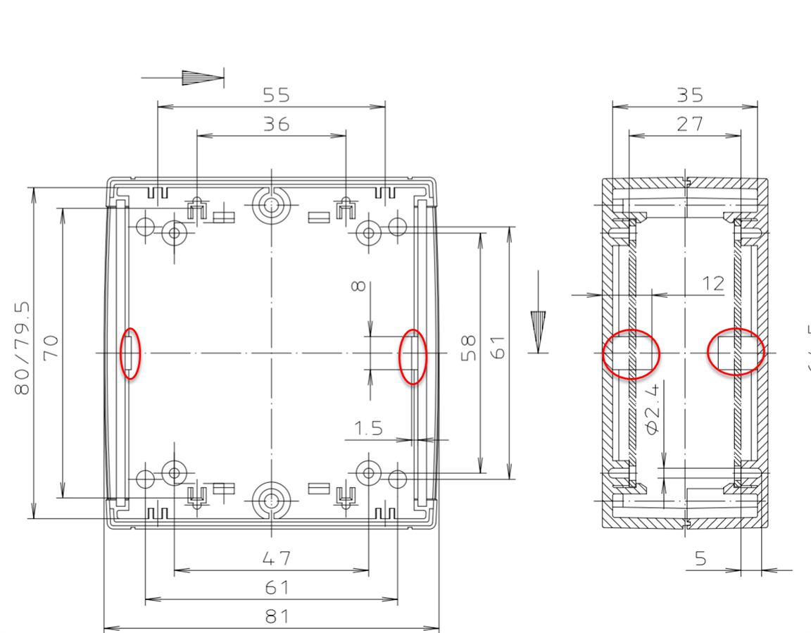
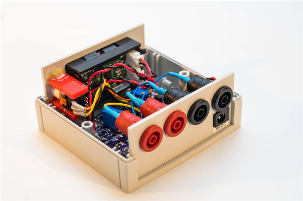
The 24A banana sockets24A banana sockets (just slight overkill) had to go on the rear panel, there's no space on the front panel : )

image

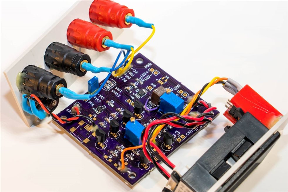
For the DPDT latching push switchDPDT latching push switch a couple of pieces of 22x10x3mm plastic were used, epoxied, to hold the switch in the correct position behind the front panel. The panel meter is from aliexpress.

I didn't screw or glue in the PCB for now:

image

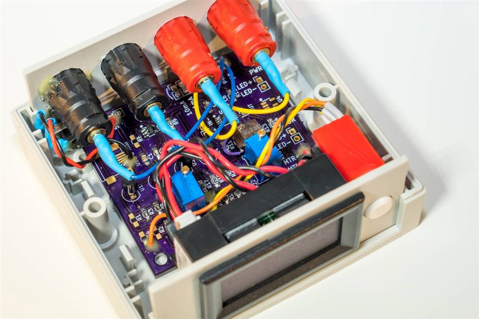
View from the other end, you can see the switch attachment to the front panel more clearly:

image


Tests

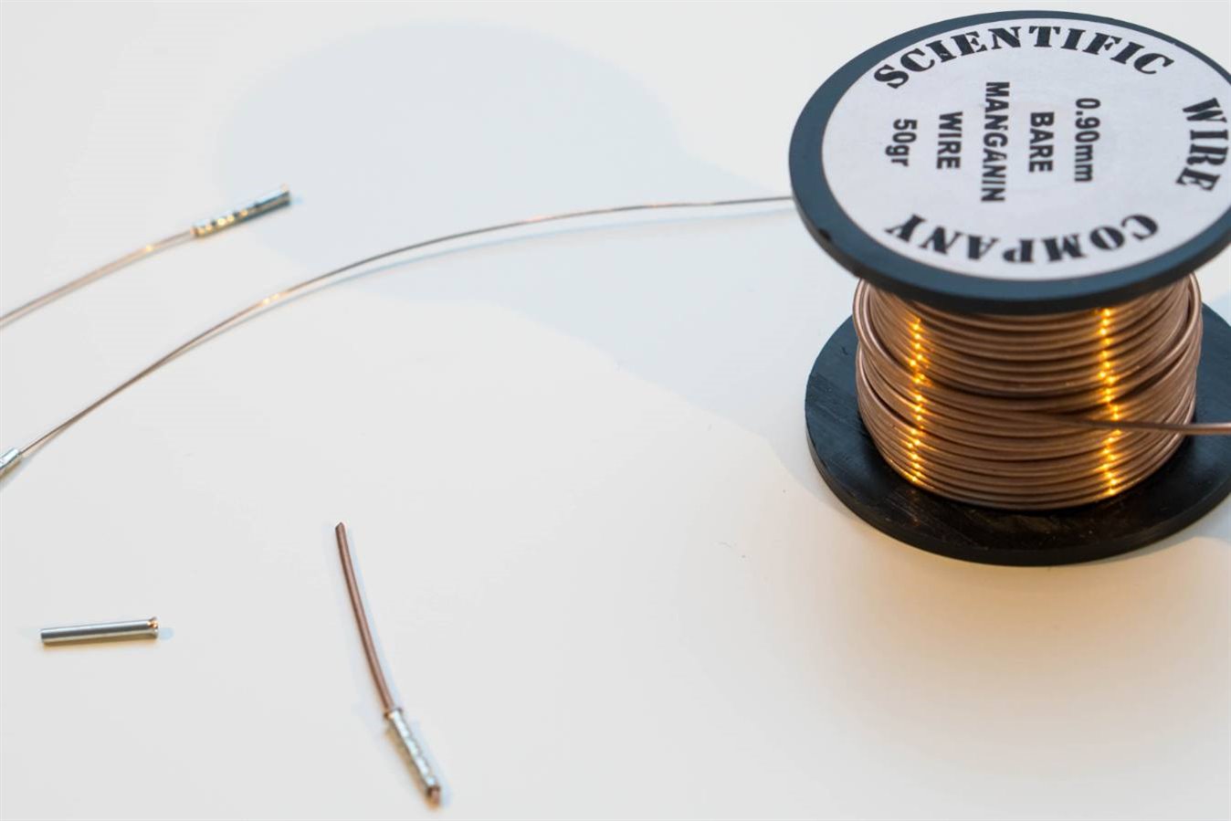
I've not done much testing, but as can be seen in the video, I measured some resistances and compared with a Keithley DMM 6500. I used some resistance wire that I'd purchased for a different project, and crimped some ferrules on the ends (this is all experimental..):

image


Here are the results:

Test # Value according to DMM 6500 Value measured by Milliohm Meter project
1 8.6-8.7 milliohm 8.7 milliohm
2 15.5-15.6 milliohm 15.4 milliohm
3 125.5 milliohm 127.5 milliohm
4 319.9 milliohm 320.4 milliohm
5 3.319 ohm 3.323 ohm


The largest discrepancy between the two meters is a 1.6% in test #3, but the difference is around 0.1% ballpark in all other tests, so it could well be that I didn't clip the connectors on the same way for test#3. There is a small difference in location each time the clips are connected and disconnected - it won't be completely identical, although I could have reduced that by not moving the test clips, and swapping the banana plug end each time. Anyway, I only intended to do quick sanity tests, not anything more accurate for now.


Also, I've not tested at a value lower than 8.7 milliohm.. there may well be a lower limit of a few milliohms, probably not of practical importance once it is in the (say) 0-3 milliohm ballpark perhaps, but I will check with a lower resistance than 8.7 milliohm at some point.

There is some occasional instability that needs investigating (mentioned in a discussion comment here: https://www.element14.com/community/people/fmilburn/blog/2018/10/18/pcb-for-a-kelvin-4-wire-milliohm-meter#start=25

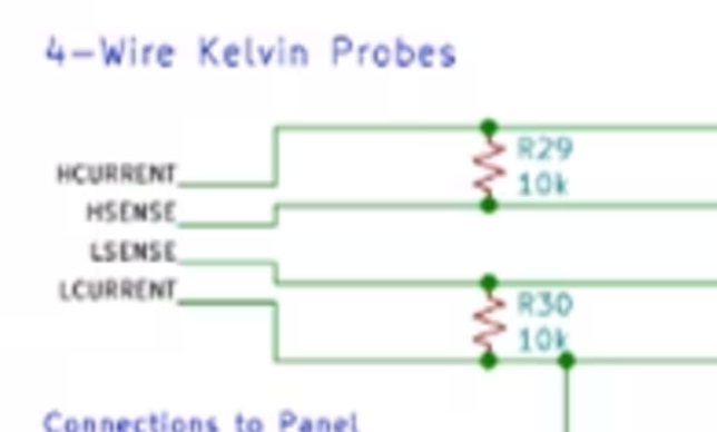
Note: there was some instability, but this is the solution; add two 10k resistors:

image

Meter Improvement (Conversion to Differential Input)

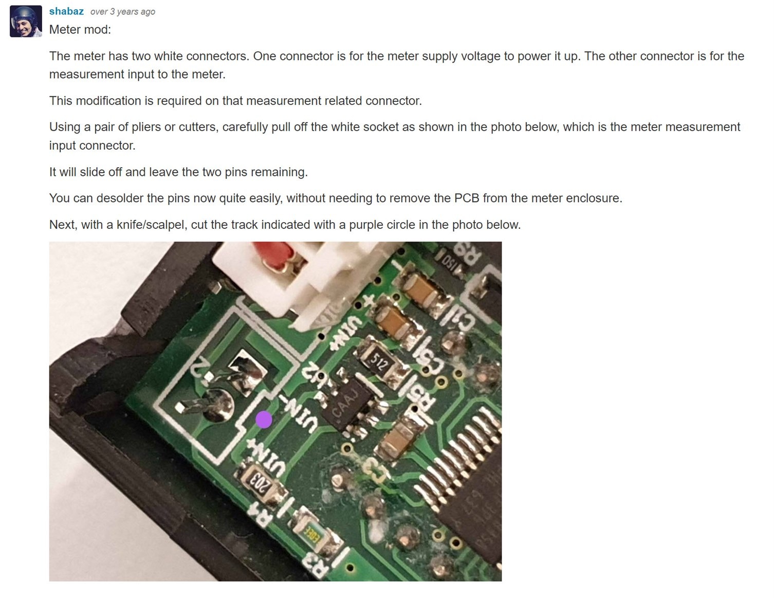
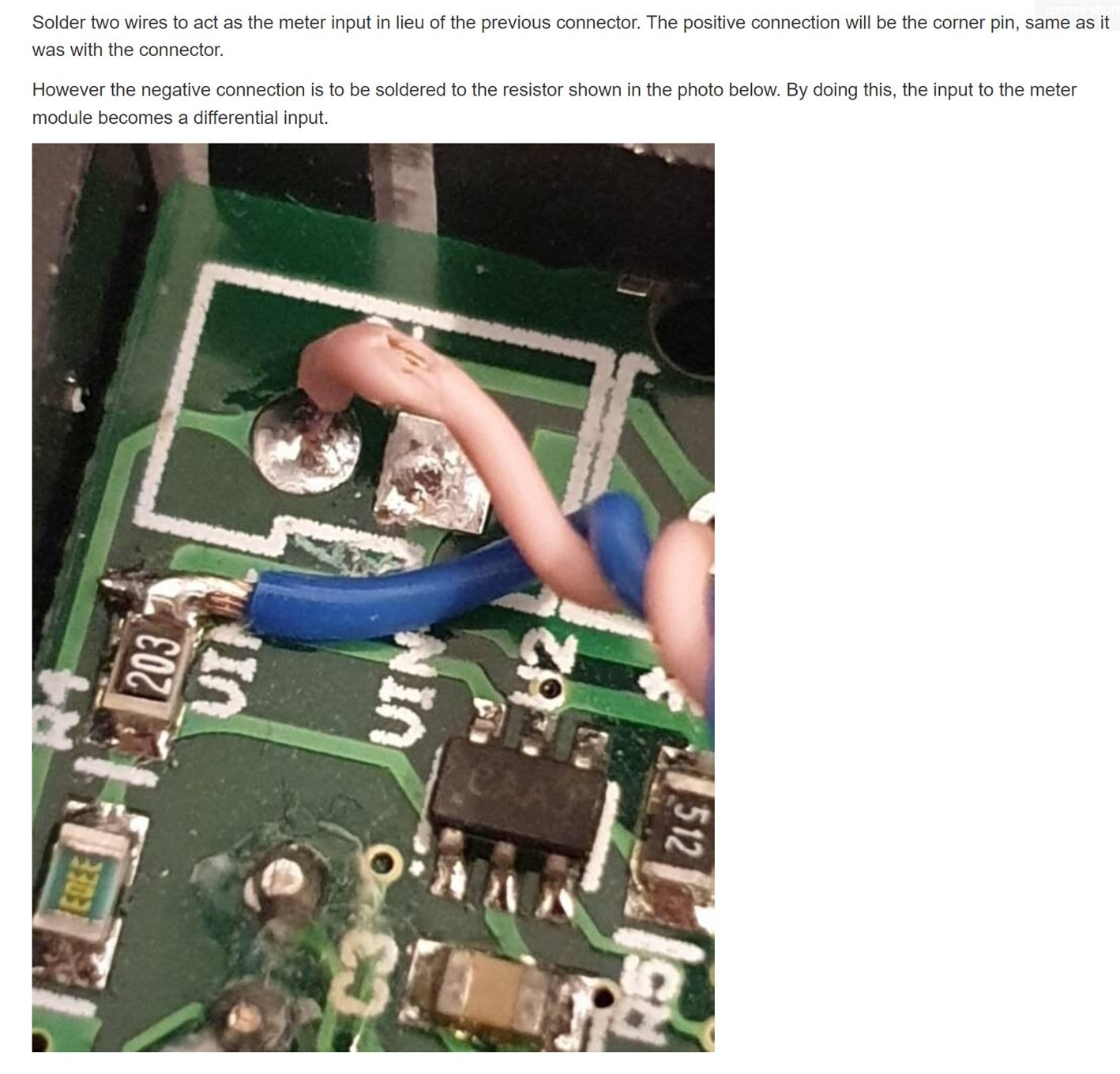
See the comments below  PCB for a Kelvin (4-Wire) Milliohm Meter for some information about how the meter can be improved, to squeeze a bit more accuracy out of it. The information is reproduced here to make it easier to follow: 

image

image

Bigger is Better?

After completing this build, I decided to start building another one, based on an interim board from Frank (it is not a version 2.0, more a version 1.5 of sorts).

This new one is broadly the same as the one described in this blog post, but with a slightly newer version of PCB. I put it in a bigger case, because I wish to eventually make this one battery powered. It is incomplete, I still need to add the battery power circuitry, and I need to drill the holes for the banana sockets.

image

A view inside the unit:

image


Summary

This is just a rev 1.0 project, but it is promising how accurate and stable it is, considering the low cost. It functions well.

It was a lot of fun to construct and try it out this Xmas! The design has a lot of flexibility, and is easy to solder and experiment with. I'm looking forward to seeing the design evolve - it will only improve I think!

I still can't get over how small it looks next to the other test instruments though : )

There is a rev 2 discussion here:  New Improved DIY Milliohm Meter V2.0 

image

  • Sign in to reply

Top Comments

  • jc2048
    jc2048 over 6 years ago +7
    That's very neat and compact. The picture of it next to the Keithley box is lovely - perhaps you should have entered it in the Question of Scale competition! How does it get on measuring the DCR of inductors…
  • fmilburn
    fmilburn over 6 years ago +5
    Hi Shabaz, That was a great review! Thanks so much. It was a lot of fun seeing it up next to the Keithley. Your build is fantastic. Most of the credit for the design reaching the current stage goes to…
  • genebren
    genebren over 6 years ago +5
    Hi Shabaz, This was a great write-up on your build and verification of Frank's work. In watching the video, I began to wonder if some of the variations in the readings between to the two instruments might…
Parents
  • jc2048
    jc2048 over 6 years ago

    That's very neat and compact. The picture of it next to the Keithley box is lovely - perhaps you should have entered it in the Question of Scale competition!


    How does it get on measuring the DCR of inductors? Is it stable?


    I'm also wondering whether you'd get a sensible value for RDS(on) for a power MOSFET. Don't see why not, though the manufacturers do their tests at a much higher current (the MOSFET I've used in the load is tested at 27.5A!) and it does vary a bit with current. It would be a very easy experiment if you wanted to try it (perhaps bias the gate with a 9V battery so that there are no complications in that area).

    • Cancel
    • Vote Up +7 Vote Down
    • Sign in to reply
    • More
    • Cancel
  • shabaz
    shabaz over 6 years ago in reply to jc2048

    Hi Jon,


    I tried a MOSFET, and got decent results I think.. so it's another nice use of the milliohm meter!

    For the test, an IRFZ44 was used, and a voltage from 4 to 10 was applied to the gate, while the milliohmmeter was connected to the Drain-Source.

    image

    According to the ratings on the datasheet, the on resistance should be less than 28 milliohm at 10V. My results are in the chart below - I measured a value of 18.2 milliohm at 10V, so it meets the spec!

    image

    • Cancel
    • Vote Up +5 Vote Down
    • Sign in to reply
    • More
    • Cancel
  • jc2048
    jc2048 over 6 years ago in reply to fmilburn

    My vote would be to keep it simple. It's very nice as a stand-alone intrument.


    But Shabaz' idea of a header is a good compromise. You could later do a small board with a processor on it. It's only a few extra pads on the PCB.


    If you're doing another version of this board, I'd suggest taking another look at the issue down at a few milliohms (the amplifier output not quite getting to the rail). The amplifier has a ref input that allows the output to be lifted away from ground. A meter for the output can measure with respect to that reference voltage (assuming the meter input is differential). With an A/D it's a bit more fiddly because you'd want the ref voltage to also be the negative reference for the converter, so if you were interested in the daughterboard approach you'd need to sketch out how that was going to work so that you can get all the right things on the header.

    • Cancel
    • Vote Up +5 Vote Down
    • Sign in to reply
    • More
    • Cancel
  • shabaz
    shabaz over 6 years ago in reply to jc2048

    Hi Jon,


    Unfortunately the panel meter doesn't have differential input : ( although, the ADC on it does support that, so it could be possible to de-solder and lift up that leg of the IC to tack on a wire). 

    As you say it would still be good to have the capability to apply a few mV to that reference pin (e.g. maybe just divided down off VCC) and then the option is there for anyone who wants to attempt the modification on the panel meter (or buy a different meter, although this one is very low-cost), or just a zero-ohm resistor to ground for anyone who doesn't want to modify the panel meter.

    Incidentally, it may be that it is already below practical values, when I short the inputs, I see 0.0008, i.e. 0.8 milliohm. But this is not guaranteed for all builds of course.


    Also, unrelated, but before I forget, there could be a need for say low-value resistors in series on the inputs to the amplifier, because I'm wondering if the occasional instability I see (the output going to 0V) could be due to the long input leads (about 1 metre long). I will insert some series resistors to see if it makes a difference. Section 4.4.5 in the datasheet mentions that resistors may help.

    • Cancel
    • Vote Up +4 Vote Down
    • Sign in to reply
    • More
    • Cancel
  • fmilburn
    fmilburn over 6 years ago in reply to fmilburn

    Thanks for the feedback! 


    For now I will keep it simple.  I like the idea of a Pi - it might even be a Pi Zero W that keeps the enclosure small but if done that will be a later revision.


    Regarding the loss of accuracy down in the milliohm region, on my current build I read 0.99 milliohm with the inputs shorted.  Looking back at the version I constructed on perfboard the reading was 1.01 milliohm.  So, not quite as low as what Shabaz is seeing but still +/- milliohm which was the original design spec.


    The thing I would most like to resolve in the next version is the occasional instability.  I can add pads for the series resistors that Shabaz highlights from the datasheet above (well spotted) on the next version if that works.  In section 4.4.6 of the datasheet they warn of input capacitance - I realize the leads can contribute but do you think there is anything on the board that should be changed?


    I have lost enthusiasm for the second range because I don't like the (admittedly simple but prone to possible mental error) change of scale.  This would be especially prone to mental error with auto ranging.  The only way to fix that I can see is with a microcontroller or Pi and ADC.  But it doesn't hurt to leave it in and it does not have to be populated.


    Regarding the schematic and board revisions, I plan to post a comment later today back on the post that has the Version 1 schematic.  In that comment I will include a revised schematic that captures planned updates.  Please feel free to critique.  After receiving comments I plan to capture them and revise the PCB within a week and make an order.  The PCB will be designed to fit the enclosure that Shabaz is using, including mounting holes, etc.   If you are interested in building it, please contact me by personal message and I will send you the PCB.  If you need any of the components on the board let me know as I will be making another order soon and will include them.  This is just a hobby for me and I appreciate the help - sharing parts is of minimal cost, so hopefully it is partial repayment for your time and interest.

    • Cancel
    • Vote Up +4 Vote Down
    • Sign in to reply
    • More
    • Cancel
  • genebren
    genebren over 6 years ago in reply to fmilburn

    Frank,


    Projects have a way of taking on a life of their own and growing without bounds, so I think it is wise to keep it simple.  Having said that, if you were to want to add some features a simpler microcontroller (MSP432, Atmel, ATtiny or ATmega) would be a good choice.  If you need help on this sort of extension, I would be glad to help out on something like that.


    This has been a great project and you have accomplished a lot.  Well done!


    Gene

    • Cancel
    • Vote Up +3 Vote Down
    • Sign in to reply
    • More
    • Cancel
  • fmilburn
    fmilburn over 6 years ago in reply to genebren

    Thanks Gene!  I almost certainly will need help :-)

    • Cancel
    • Vote Up +3 Vote Down
    • Sign in to reply
    • More
    • Cancel
Comment
  • fmilburn
    fmilburn over 6 years ago in reply to genebren

    Thanks Gene!  I almost certainly will need help :-)

    • Cancel
    • Vote Up +3 Vote Down
    • Sign in to reply
    • More
    • Cancel
Children
No Data
element14 Community

element14 is the first online community specifically for engineers. Connect with your peers and get expert answers to your questions.

  • Members
  • Learn
  • Technologies
  • Challenges & Projects
  • Products
  • Store
  • About Us
  • Feedback & Support
  • FAQs
  • Terms of Use
  • Privacy Policy
  • Legal and Copyright Notices
  • Sitemap
  • Cookies

An Avnet Company © 2025 Premier Farnell Limited. All Rights Reserved.

Premier Farnell Ltd, registered in England and Wales (no 00876412), registered office: Farnell House, Forge Lane, Leeds LS12 2NE.

ICP 备案号 10220084.

Follow element14

  • X
  • Facebook
  • linkedin
  • YouTube