Table of Contents
Introduction
In the search for bargain microcontrollers that are actually still available during the world semiconductor shortage, I came across a DA14531 module by Renesas / Dialog Semiconductor that looked great, and really cheap (just over £2 in single quantities). I ordered this one: DA14531MOD
This module will be really useful where short-range wireless connectivity is needed. The module can be used in a number of configurations, but this blog post only examines a standalone configuration where the module uses its built-in internal microcontroller to run code, just like any other microcontroller chip, but with BLE wireless capability too. You could use the BLE capability to (say) control or configure things with a nearby mobile phone, such as switching on a relay when an icon is clicked on your phone, or to capture data to the phone, for instance from a sensor connected to the module.
Initially, I couldn't make use of it because nearly all the examples used a development environment called ARM Keil MDK, which at the time needed to be purchased. It can become non-trivial trying to port the project files for large projects to other environments, and so this project ended up on a shelf for six months. However, now Keil MDK is available in a free Community Edition, it was time to reassess, and I had a lot more success this time around!
This blog post documents how to get going with it. I have only experimented with the module for a short time, so I’m still learning how to make best use of it, but I’m keen to use it further.
What is it?
The DA14531MOD module is just slightly bigger than a micro SD card and is very easy to physically work with because it has generous 1.5 mm spaced connections.

Internally, the DA14531MOD module contains a 16 MHz DA14531 microcontroller with built-in Bluetooth LE capability, crystal, Flash memory, on-board antenna, and all other supporting components to use it all. The entire module is ready-to-use, no additional components are needed – just attach a power supply or batteries : )
The diagram below is from the DA14531 PDF datasheet. The chip contains an ARM Cortex-M0+ core, 48 Kbyte RAM for programs and data, Bluetooth 5.1 core (with built-in ROM containing the protocol stack for it), and quite a nice mix of peripherals, such as I2C, SPI, UART, quadrature (rotary) decoder and a 10-bit ADC with up to 4 inputs. There is good pin multiplexing, such that almost any peripheral can be interfaced to almost any pin on the chip.

(image source: Dialog Semiconductor datasheet)
There are not a lot of pins, so you won’t be able to use all the peripherals simultaneously.
Working with the Module
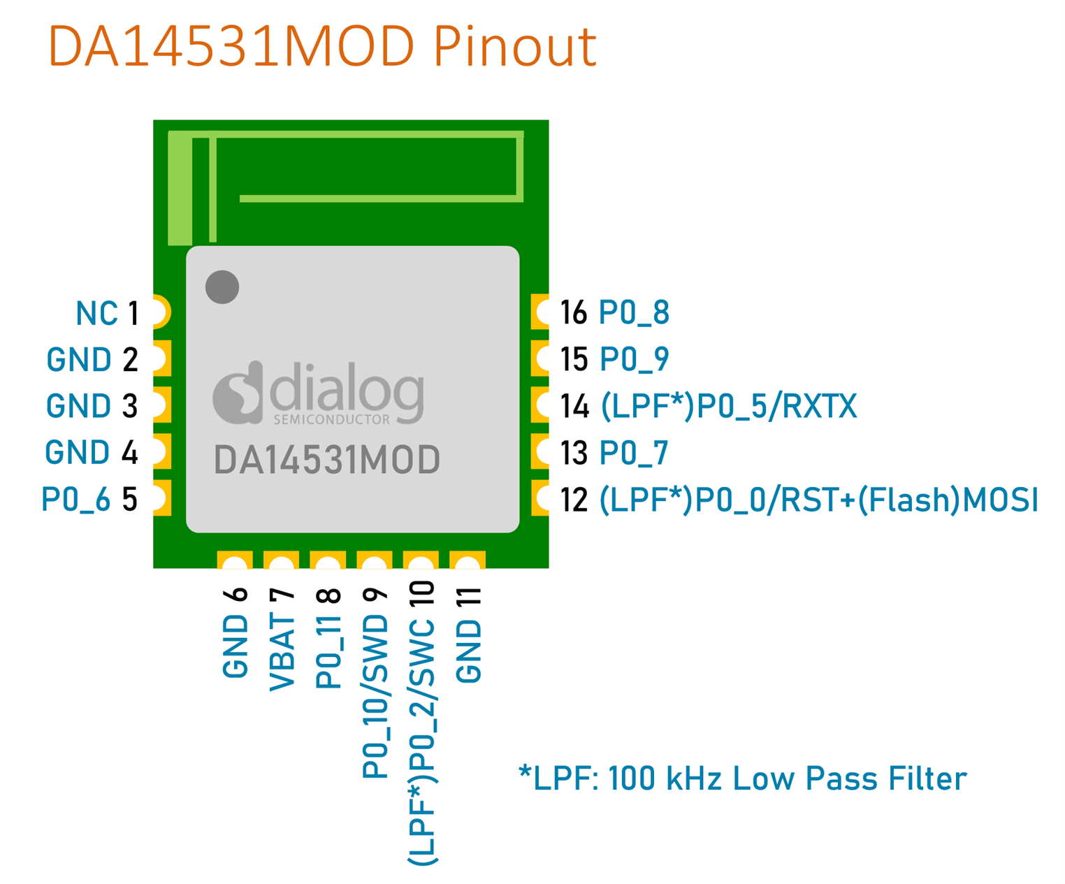
The pinout is shown below; the GND pins are already connected together on the module, but it’s recommended to connect them all together on the circuit board too, and to connect the NC pin to them as well.
There is already internal supply decoupling inside the module, but it doesn’t hurt to add a bit more.
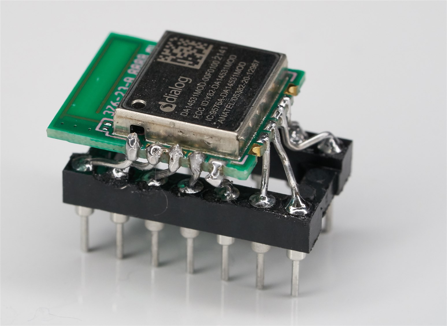
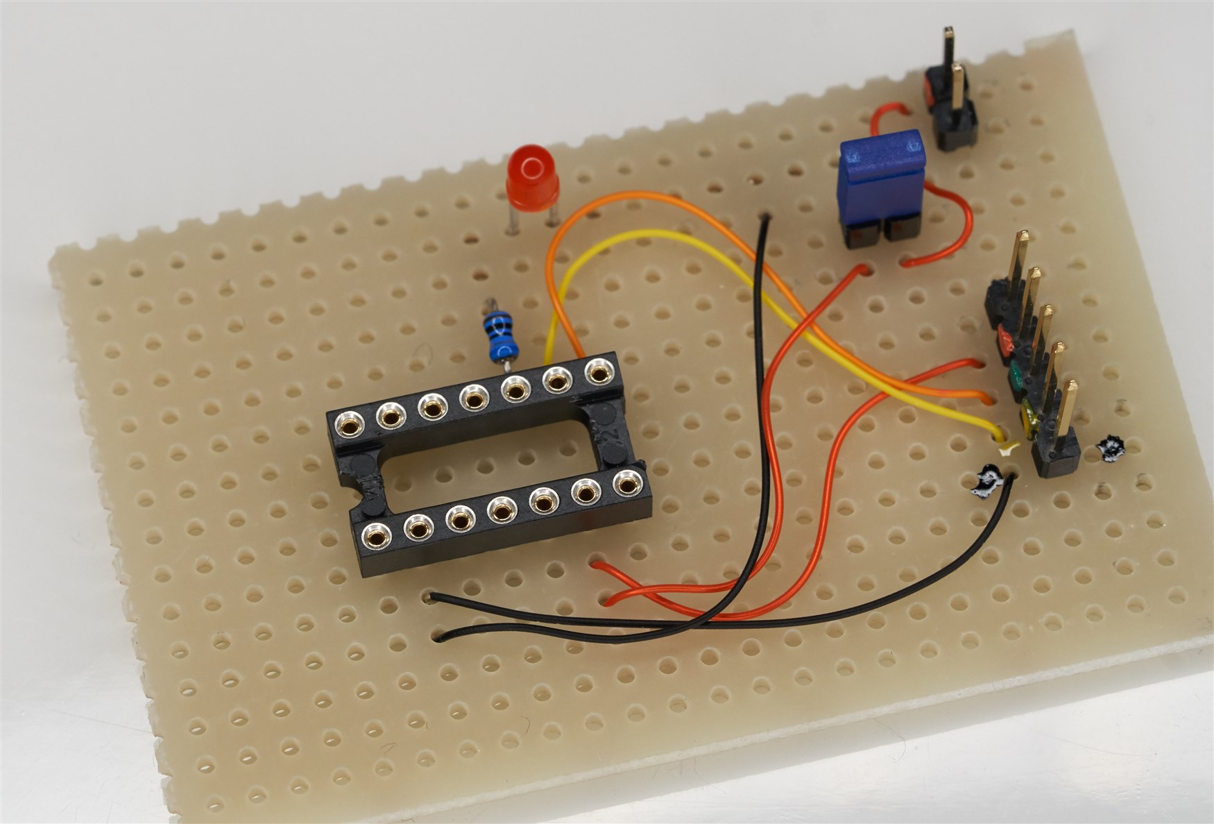
If desired, a little pluggable module can be made, to prototype with it more easily:
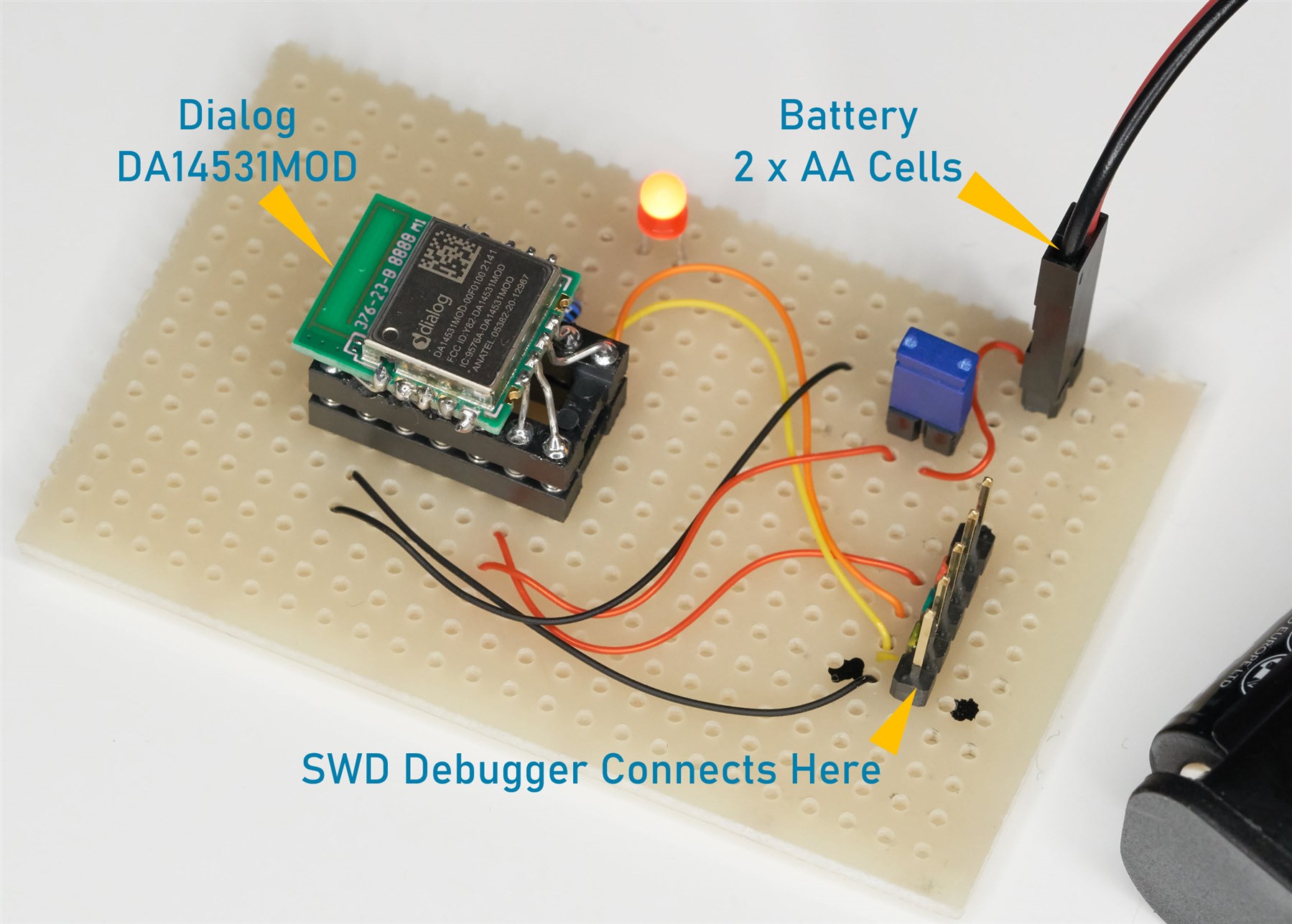
Here is how the module was wired up to experiment with it:
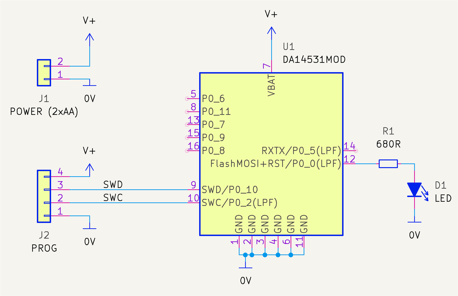
It’s a trivially simple circuit, which is great. There’s not much to assemble!
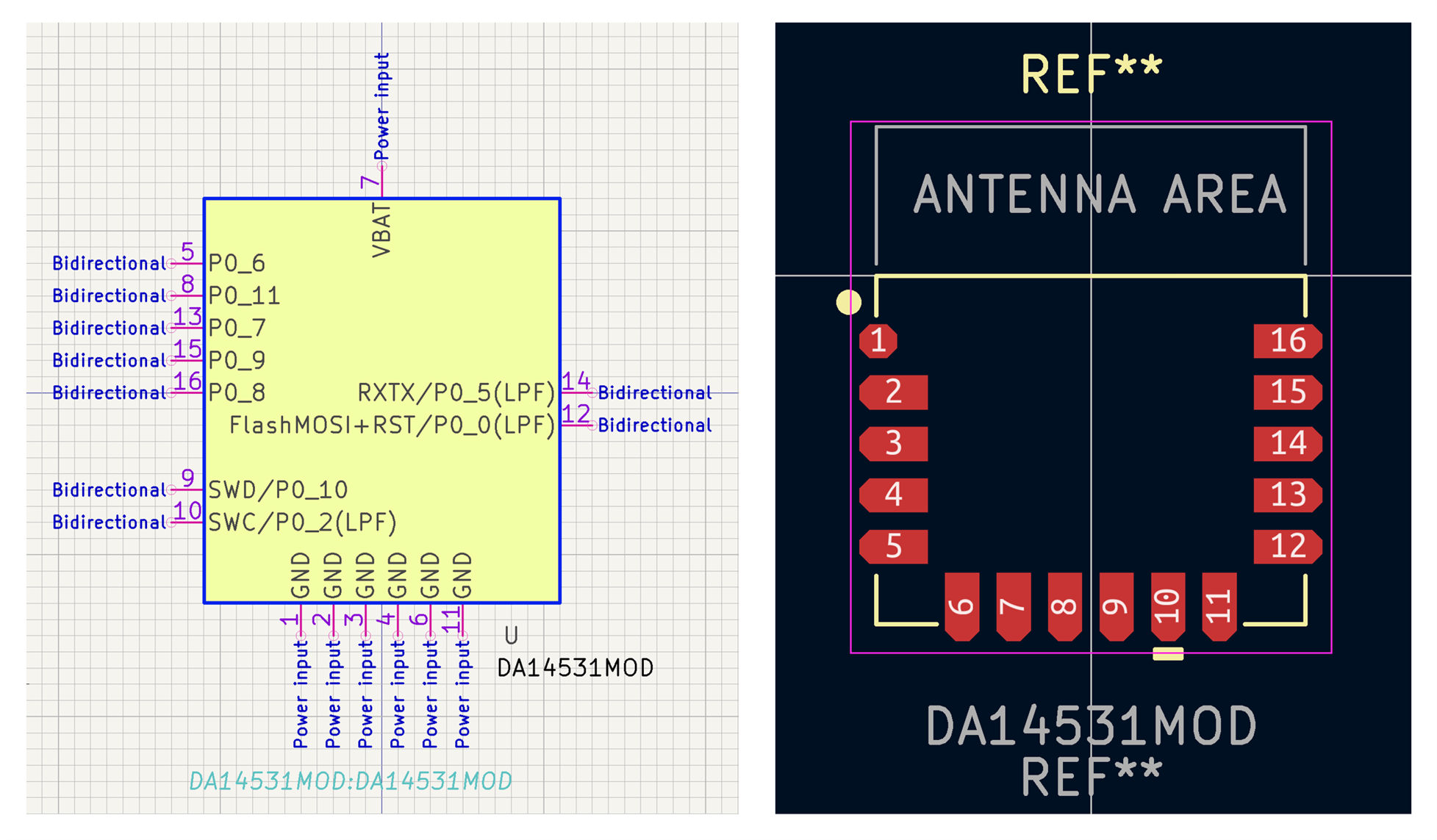
KiCAD Symbol and Footprint
I created a KiCAD PCB CAD symbol and footprint, but I've not tried them yet, so there may be errors.
Debugger Tool
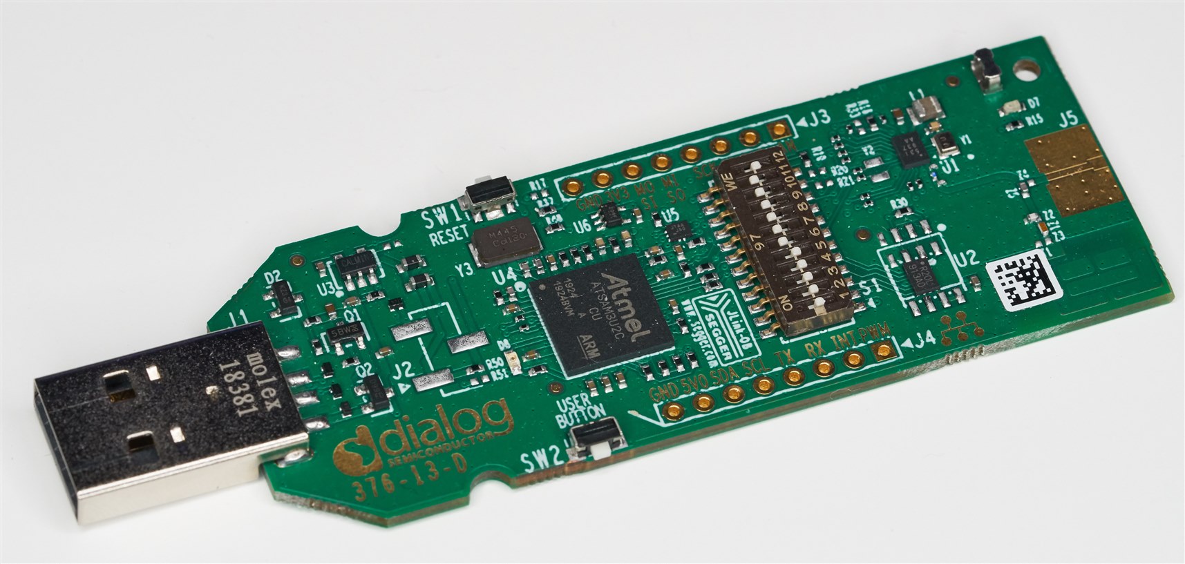
Some sort of programmer device is required. There are actually quite a few options, for instance it’s possible to program the module using a serial UART connection. However, probably Serial Wire Debug (SWD) is a better choice for development. There is a cheap DA14531-00FXDEVKT-U development kit (this is the order link to it: DA14531-00FXDEVKT-U which contains an on-board debugger, but it requires the target chip on the development kit to be removed (for instance with hot air) so that you can patch the connections to your target board. The process to remove the chip, and how to wire up the connections, is described in an application note.
Another option is to find any development board for any ARM Cortex-M chip, and connect to the built-in J-Link SWD debugger that is often present on such boards, in case it works for other microcontrollers. I was fortunate enough to have a separate J-Link Lite board, which came with a Maxim microcontroller dev board (apparently according to the Internet, the license terms do not allow such a J-Link Lite board to be used with a different microcontroller, but I certainly didn’t sign or click on any agreement, so legally I see no issue).
Yet another option could perhaps be to turn a Pi Pico into a general-purpose SWD programmer, using the PicoProbe project. There is also the possibility of taking a ST Microcontroller development board and re-flashing the built-in J-Link to turn it into a generic J-Link debugger. Apparently it only works for boards with embedded J-Link, and not for the standalone ST-Link programmer.
I have not tried most of these methods; I just used the J-Link Lite board since I already had it. The J-Link Lite board is shown in the photo below. It came with a very small connector, but there were some empty pads alongside it, so it was easy to patch wires to add a prototyping-friendly 0.1” spaced connector too.

EDIT: Another method that works nicely is to use an Infineon XMC 2Go board, which is ultra-cheap : ) I used this board: KITXMC2GOXMC1100V1TOBO1
The XMC 2Go board is a microcontroller board with an in-built J-Link debugger. The board can be converted to just a J-Link debugger in a couple of methods that do not require any hot air tool. The two methods are described here.
Method 1 (the slightly more awkward method) requires cutting two tiny traces. They are quite tiny! I used an engraver with a bearing cutter bit (see this blog post) and it was very simple to do with that.

Next, connect up three wires as shown here:

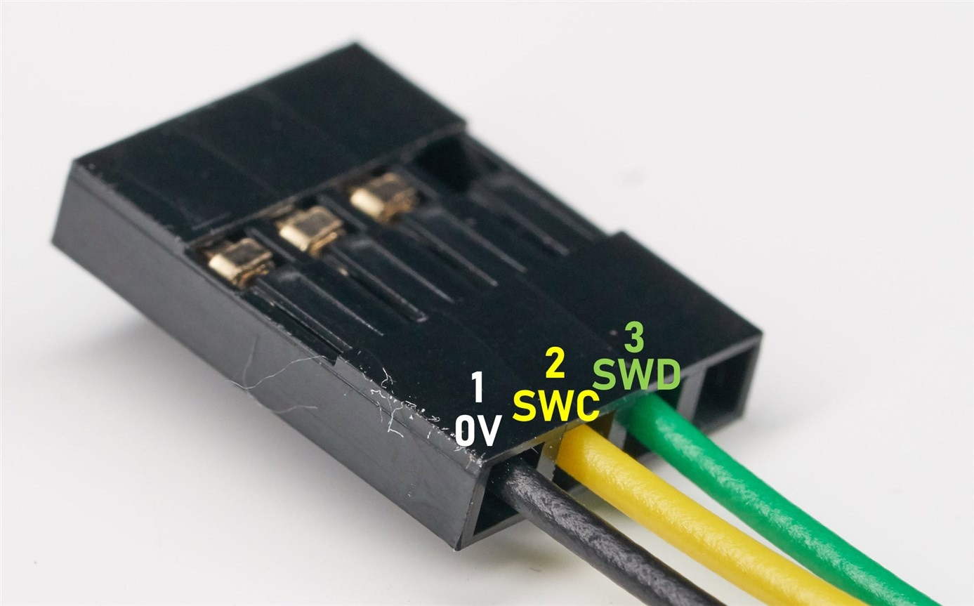
There's no standard pinout for SWD for 0.1" SIL header pins, so I use the convention shown in the photo below for my projects. Pin 4 is unused (it would be VTARGET normally, for the debugger to detect the logic level voltage used on the board), and an optional pin 5 can be used for debug/information messages, called SWO.
That's it, the board is ready to use as a SWD debugger/programmer : ) When you plug it in, an upgrade message may appear (in my case, it upgraded twice), select Yes to upgrade.
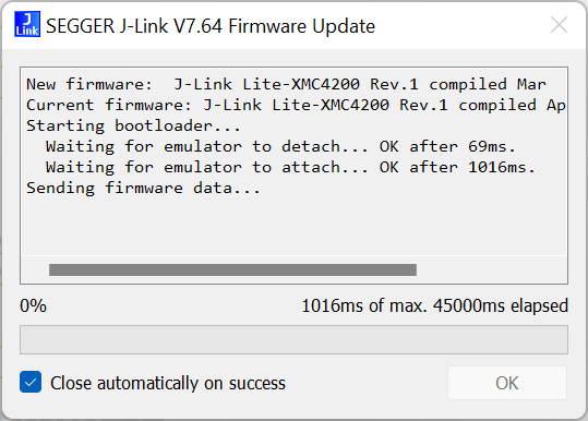
For the second method, if you don't feel comfortable cutting the traces, then it is possible to just remove the two resistors that are on the top side of the board, and solder to the other end of the resistors, inserting two 100 ohm resistors in-line.
The diagram below shows what to do for this second method.

In summary, there are a ton of options for SWD debuggers, and whichever of those is chosen, the SWD method is what I’ll be using for this blog post.
Once you have a SWD capable tool, four connections are made to the board: 0V, SWC, SWD, and (if the tool has such a connection then it must be connected) a connection to the supply voltage called VTARGET, which the SWD debugger uses to recognize what voltage levels to use. In my case, I powered the DA14531 module using two AA batteries, and so the VTARGET pin on the J-Link Lite was connected to the positive supply from the battery as shown in the circuit diagram above.
Software Development
In order to write code for the DA14531, it’s best to use the ARM Keil MDK development environment (see blog here for info on Keil MDK), because most of the Dialog Semiconductor example apps are Keil MDK projects already. Keil is quite easy to use.
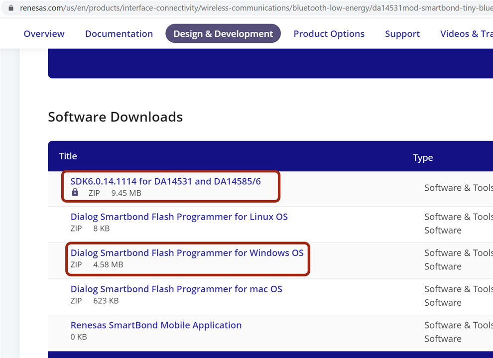
As well as the Keil MDK Community Edition software, you’ll also need the Dialog SDK downloadable from the product page. The SDK has a folder containing example apps; not all of them run on the DA14531 without some (usually small) modifications, since they were written for another Dialog chip as well.
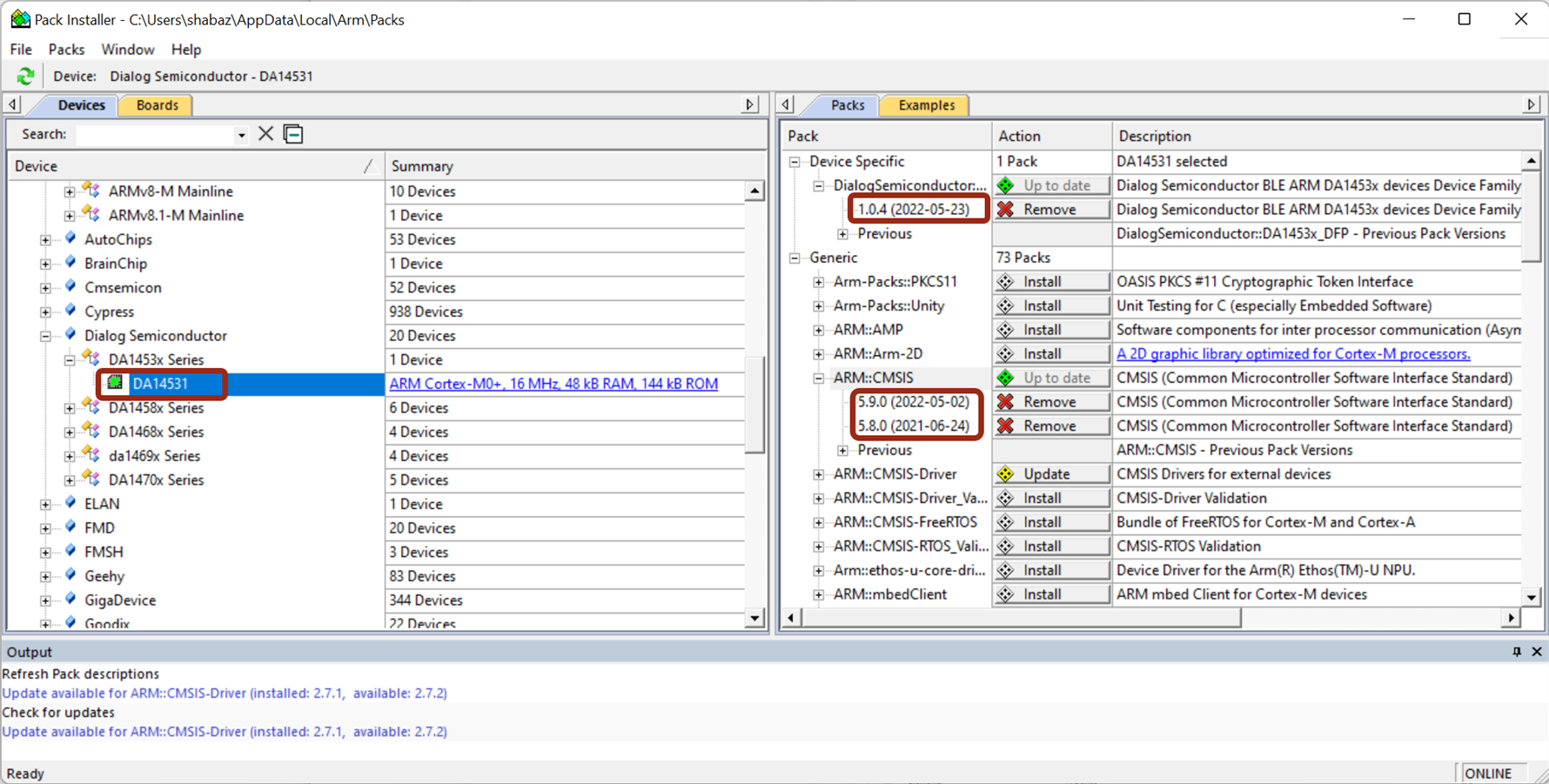
As part of installing Keil MDK (or at any time afterwards, just select Project->Manage->Pack Installer) you’ll get prompted to install software packs. Select the Dialog DA14531 device in the left pane, and then choose in the right pane to install the device-specific pack as shown in the screenshot below. Make sure the ARM::CMSIP pack is also installed if it is not already done.
You’ll also need a tool called Dialog Smartbond Flash Programmer which you could install now, or later when you’re ready to write the built firmware for your application into the DA14531 module. If you install it now, it will automatically run after installation, but you can just close it, since it’s not needed yet.
To open an example project from the Dialog SDK, in Keil MDK, select Project->Open Project and navigate to the SDK’s target_apps folder, for instance DA145xx_SDK\6.0.16.1144\projects\target_apps and then choose the ble_examples folder for now, and then pick the ble_app_peripheral folder since that’s a popular BLE scenario, and then go into the Keil_5 folder, and then open the ble_app_peripheral.uvprojx project file that you see there.
Now, on one of the toolbars there is a target selection, which may be set to (say) DA14585. Click on the drop-down and select DA14531 as shown in the screenshot below. This is easy to miss, but is obviously quite an important step : )

The left pane shows the project files and folders, which you can click on to view on the right side code pane. You can set the left pane to a functions view too, if you don’t wish to navigate by file name.
Each BLE device can have a name. It can be changed as shown below, by editing the user_config.h file. It’s good to do this now so that you can identify it easier later:

Building Code
To build the entire code, click on the highlighted toolbar icon in the screenshot below, or alternatively click on Project->Build Target or press F7. Occasionally you may need to click on Project->Clean Targets first.
![]()
Once the code has compiled, you should see no errors or warnings in the Build Output pane, as shown here:

Controlling an LED
Before the code is run, it will be useful to make a couple of quick code modifications, in order to control an LED.
The circuit diagram earlier showed an LED connected to GPIO P0_0. That particular GPIO pin can also be used as a reset pin, and so if we prefer to use it as an output, then the reset function needs to be disabled.
In the file called user_periph_setup.c, in the periph_init function, add a line containing:
GPIO_Disable_HW_Reset();
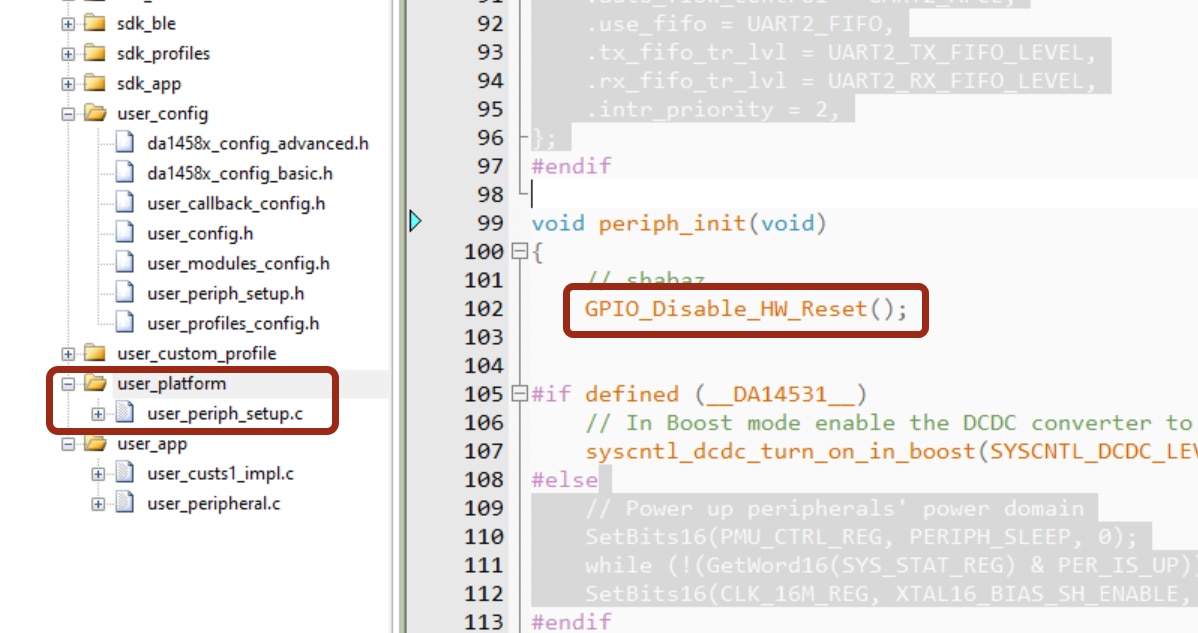
The LED GPIO pin is defined in user_periph_setup.h and I changed the pin to GPIO_PIN_0 as shown below, since that is the pin that the LED is connected to in the circuit diagram shown earlier.

Now the code can be rebuilt by selecting (as before) Project->Build Target, and there should be no errors.
Running the Firmware from RAM
To run the built code, select Project->Options for Target DA14531 from the top menu bar. The window that appears is used for all sorts of configuration stuff for the project. There are multiple tabs in the window. In the Output tab, ensure that Create HEX file is checked. Then, in the Debug tab, select J-LINK/J-TRACE Cortex in the drop-down box at the top-right.
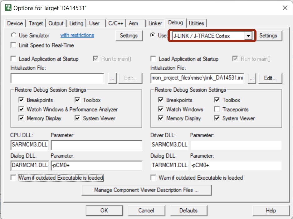
You’re now ready to run the code! To do that, ensure the circuit is powered up (I used 2 x AA cells), the J-Link SWD debugger tool is connected, and then click on the Start/Stop Debug Session icon shown below, or select Debug->Start/Stop Debug Session from the top menu bar.

The view changes to a new perspective, suitable for running and debugging code. There are three main controls that are useful, which are highlighted in the screenshot below. From left to right, they are Reset CPU, Run and Stop.
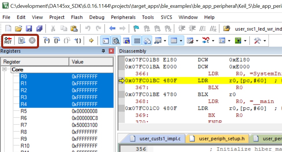
Press the Run icon and the code will run on the DA14531 board! It won’t do anything noticeable; see the next section, Connecting to the BLE Device for that!
To abort and go back to the coding development perspective, press the Stop icon to the right of the Run icon, and then select Start/Stop Debug Session as before.
Connecting and Controlling the BLE Device
On your phone, download an app called LightBlue. There are other apps you could try from your PC, but it’s quickest to just test with your mobile phone for now.
Once it’s running, it will automatically scan for nearby BLE devices. You can recognize your BLE device because it will have a very strong signal strength since it’s nearby. The signal strength is in dBm and in practice will be a negative value. A value of -37 dBm means a stronger signal than (say) -50 dBm. You can also recognize the device by looking out for the name that was typed in the code as discussed earlier.
If you can see the name, then the code is running.
Connect to the device, and the display will be full of initially cryptic-looking stuff, but scroll down and search for LED State. The screen looks slightly different for iPhone and Android, but it will be fairly similar to the screenshot below.
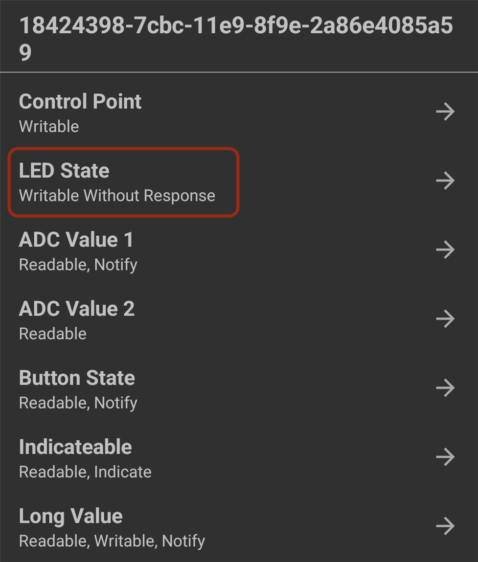
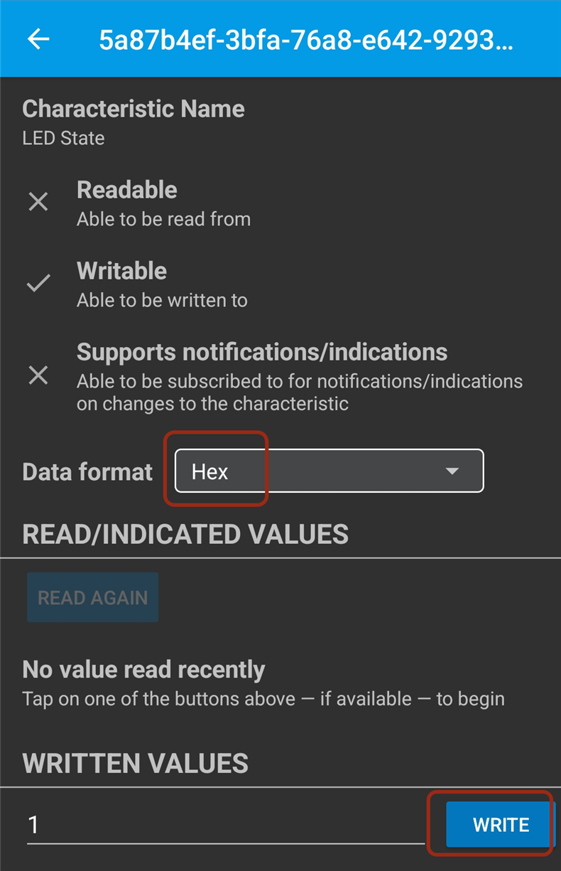
Now you can control the LED from the phone : ) Select a data format (I chose Hex, but it’s up to you) and then click on the Write button to type in a value. A value of 1 will turn on the LED, and 0 will switch it back off.
Writing the Firmware to Flash
Above, in the section Running the Firmware from RAM, the SWD debug tool was used to write the executable binary file temporarily to RAM. In order to permanently have the binary file inside the DA14531 module, it needs to be written to the Flash chip inside there. To do that, use the Dialog Smartbond Flash Programmer program that was installed to the PC earlier. Start it up, and it will detect the connected SWD programmer, so select it as shown in the screenshot below, and then click Browse and navigate to the .hex file that was built earlier. Next, click Erase and then Program as shown in the screenshot.
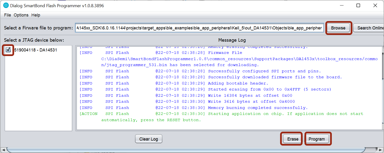
Everything is done, and the code should be running : )
You can disconnect the programmer, and if you disconnect and reconnect the power to the board, you’ll see that the firmware is permanently installed and it will run.
Summary
A simple Bluetooth LE project was created with the DA14531 module. The circuit was trivial to assemble, and an example code application was modified slightly, to control an LED remotely using a mobile phone.
The built code can be tested easily and quickly using the free ARM Keil MDK development environment, and then the code can be permanently written to Flash using a separate software tool downloadable from the Dialog Semiconductor website.
Thanks for reading!

Top Comments
-

shabaz
-
Cancel
-
Vote Up
+1
Vote Down
-
-
Sign in to reply
-
More
-
Cancel
-

MarkusAnd
in reply to shabaz
-
Cancel
-
Vote Up
0
Vote Down
-
-
Sign in to reply
-
More
-
Cancel
-

shabaz
in reply to MarkusAnd
-
Cancel
-
Vote Up
0
Vote Down
-
-
Sign in to reply
-
More
-
Cancel
-

MarkusAnd
in reply to shabaz
-
Cancel
-
Vote Up
0
Vote Down
-
-
Sign in to reply
-
More
-
Cancel
Comment-

MarkusAnd
in reply to shabaz
-
Cancel
-
Vote Up
0
Vote Down
-
-
Sign in to reply
-
More
-
Cancel
Children