


This series of posts relates to the work of Jan Cumps and Robert Peter Oakes in their WIP Programmable Electronic Load blog.
In this post I'm going to look at stability and the way we might get some measure of how good it is other than looking at the step response as
I did in the earlier blogs. I did a post in the WIP blog on stability, so I'm repeating myself a bit, but it seems sensible to go through it
again before adding a bit more about interpreting the features of the open-loop response and how they relate to the closed-loop response of
the final instrument. Note that I'm learning how to do this as I go along, so this isn't a tutorial and you can't depend on it in the same way
as you could with a textbook - keep a skeptical mind and question what I do and whether it makes sense to you. If you know I'm getting it
wrong, I'd appreciate if you said.
To look at the stability I'm going to open the loop so that it's no longer functioning with the overall negative feedback that corrects for
the error term; now it just behaves like an amplifier. Here's how it looks as a circuit in the simulator:

I still don't know how you're supposed to do this, but I've developed my own method which seems to work ok although it's a bit fiddly to set
up. Then I'll plot the frequency response for the signal magnitude and for the phase - the two of them together are usually known as a 'Bode
plot' and are the basis of one way to derive a measure of the stability of a system. The one thing that complicates things for me with this
circuit (and my method of doing this) is that the bias for the MOSFET comes from the loop action, so to get the frequency and phase response,
which the simulator will do with a very small sinewave, I need to get that bias set up, which I do by manually putting a DC offset on the
generator.
It doesn't matter where I open the loop. We're assuming that the circuit is linear for small signals and won't limit, so the overall response
is the same whichever order the individual elements around the loop go in. I've chosen to do it after the integrator. The normal input is held
constant and a voltage generator drives the point where I've broken the loop.
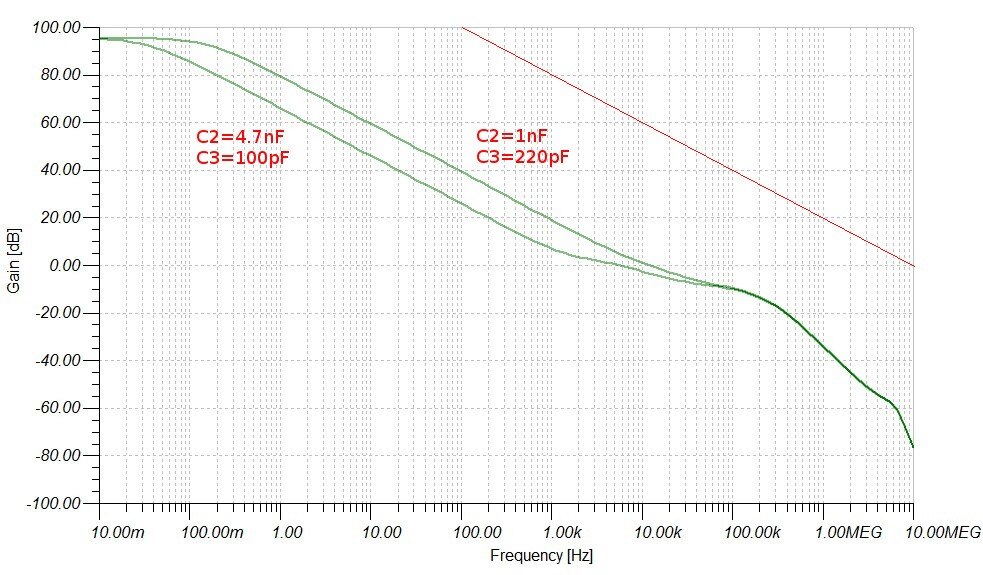
I'm going to start with the situation where there's no inductance in the output circuit and look at the two cases from the previous blogs -
one with the original C2=4.7nF/C3=100pF values and the other with my revised C2=1nF/C3=220pF values.
Here's the magnitude plot. The simulator gives this to us as a gain in dB. I've combined the responses for the two cases on the same graph so
we can contrast them and see how they differ. [Just for comparison, the red line is the open-loop response of one of the op-amps used in the
circuit. I drew that on by hand, using the curve in the datasheet for reference].
If you're not used to using dBs, or are unpractised in their use, this is a voltage plot - what's being measured is simply the ratio between
one voltage amplitude and another (the output amplitude divided by the input amplitude) - so a gain of 0dB is a ratio of 1 (ie the output is
the same amplitude as the input) and each 20dB is a factor of ten (so 20dB is a gain of 10, 40dB is a gain of 100, 60db is a gain of 1000, and
so on). Negative figures are attenuation, so -20dB is a gain of a tenth. [Strictly speaking, we shouldn't use the term dB for a voltage gain
without specifying the impedances involved, but everyone uses the term for simple ratios like this, so I will too.] Plotting both the
magnitude and the frequency as log scales became the norm because simple circuit elements like capacitors and inductors have responses that
are basically straight lines on such a graph and, before the days of computer simulation, that allowed engineers to graphically piece-together
a circuit response from the circuit elements.
Here now is the phase plot. Again I've composited the two curves together - this time I've made one of them slightly fainter than the other so
that we can distinguish them properly. Remember that this is still the situation with no lead inductance in the output circuit.
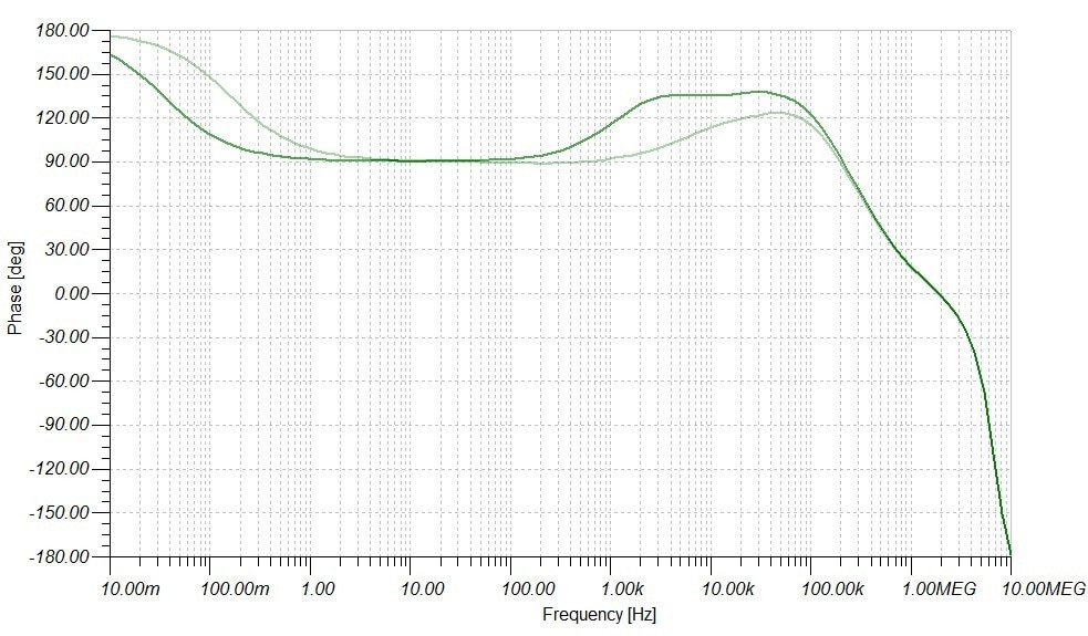
The critical phase here is 0 degrees. (In a text or lecture, this will be presented to you as 180 degrees - see the note below for an
explanation of how what I'm doing here differs from the normal treatment. Sorry if this is a bit confusing.)
The shapes of the curves are quite complicated. Each part of the curve relates to different components within the circuit. Each time you see
the curve change direction, that's another component coming into play. The components that affect this are the capacitors and inductors since
they each contribute to the frequency response. Some of those components are obvious - they're drawn as capacitor symbols on the schematic -
but others aren't - the MOSFET has a fair amount of intrinsic capacitance, the leads in the output circuit will have some inductance, and both
of the op-amps have an internal capacitor to tailor its frequency response and ensure it remains stable at higher frequencies. As far as I can
see there are five integrators and two differentiators in total. We can already see, by plotting two curves, the way that C2 and C3 influence
both the frequency curve AND the phase curve. I'm not going to show all the experiments I did here, because there is too much of it, instead
I'll just say that C2 is responsible for that initial slope down on the gain plot and C3 is what counters that and lifts it at the end. [Keep
firmly in mind that this response is for the open loop and that the overall response will be different for the loop once it is closed and the
feedback is operating.] C2 has been sized to be the 'dominant pole' in the system - it rolls off the response at a much lower frequency than
the other integrators. The whole of the plot from 1Hz up to 1kHz is determined by that capacitor - it gives the 20dB per decade roll-off of
the gain plot and the 90 degree phase change on the phase plot. That's deliberate because it leads to a well-controlled situation that isn't
dependent on a fragile balance between several very similar elements that would put you at the mercy of small changes due to component
tolerances. Having a dominent pole is the standard way of compensating a transistor amplifier to ensure high frequency stability when you have
feedback over several stages and is also what is done for an internally compensated op-amp (which is, after all, a multi-stage transistor
amplifier that will normally operate with feedback). So far, with C2, what's being done here doesn't really differ from what an amplifier
designer would do. What's different is the area between 1kHz and a few tens of kHz where the differentiator comes into play. It lifts the gain
(there must be another factor at work here because it doesn't manage to get the response level) and it changes the phase in such as way as to
(hopefully) improve the phase margin. Above that, there are several other factors coming into play, including the response of the op-amps and
the RC network made up of the gate capacitance of the MOSFET and the gate drive.
In terms of stability, both of these curves are very safe. Up to the points where the gain curves cross the 0dB line, the phase is more than
90 degrees away from the critical phase of 0 degrees. And at the point where the phase falls to 0, the gain is something like -45db. Those
would be regarded as very safe margins.
Now here are the curves for the 4.7nF/100pF case with lead inductances (each lead, so twice for the circuit) of 0uH, 10uH, 100uH, and 1mH, so
that we can see the effect of inductance in the output circuit.
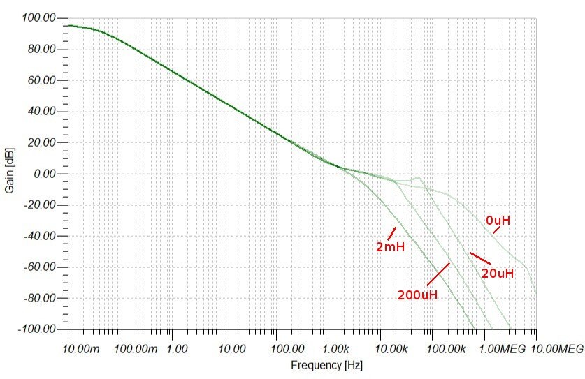
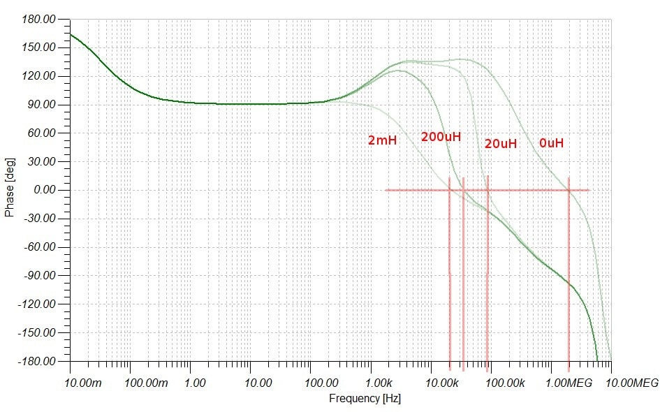
The inductance pulls the phase response down and steadily lowers the frequency at which a phase of 0 will occur. We can see why lifting the
phase response with the differentiator was of value because it partially counters the change, though it can't stop it if we throw enough lead
inductance in there. The effect on the gain curve is somewhat less evident, with most of the change occuring below the 0dB level - above that,
it's still dominated by the integrator response. However it's uncomfortable the way the gain curve sits just below the 0dB level, particularly
in the 20uH case where it moves back up before dropping away. Since that's close to the 0 degree point for 20uH, the gain and phase margins
are poor and the response will ring badly. The step responses in part 3 do show the 20uH case as ringing badly. If I were the designer,
that point would concern me, because you could imagine the whole thing actually oscillating if component tolerances resulted in the gain
curve moving up a bit more and the user happened by chance to get the output leads the right length. Overall, the phase margins are quite good
but the gain margins are poor - the value of the differentiator in improving the phase is countered by the way it brings the gain curve up
towards the 0dB level.
Could this be done better [the design I mean, not my amateurish analysis]? To be honest, I don't have a clue. I don't even know how you should
design such a circuit from first principles. Perhaps someone would like to tell me in the comments, or at least give me some clues.
Notes:
One of the roadtests currently on the go is for a TI educational converter board that includes a very good programme of experiments with
commentary and discussions. In the commentary that goes with the experiments, the critical phase is presented as being 180 degrees. Since I
don't know anything about all this theory and TI most certainly do (they wouldn't do very well at designing DC-DC converter chips if they
didn't), my first thought was that I was getting things horribly wrong. However, when I first did this on Jan's WIP blog, I had sat down and
considered it very carefully and convinced myself I was right, so why the difference? Here's the argument: I am looking at the phase all the
way round the loop; if a sinewave is applied at such a frequency that the loop phase is 0 degrees, that will reinforce the original and the
oscillation will grow; if the loop phase is anything else it will tend to counter the original change, though if it's close to zero that may
take multiple cycles to settle which we would see as ringing. So is TI wrong? No, of course not! What's happening is that we're both right -
basically, we're talking about different phases. My phase shift is once around the entire loop to the point where I started and it includes
the 180 degrees implicit in the term 'negative feedback'. They are talking about the forward path and assuming the the response of the
resistive feedback plays no part, which for an amplifier or a converter at low frequencies would be true. So I think that's why we differ,
though I am slightly unsure of this - I really ought to see if I can get an up-to-date, modern, control systems textbook to work from rather
than the one I'm using [1] and see if I can understand better the conventional ways of doing this. I don't think it matters in the results I'm
getting - I've got a cross check by interpretation of the step responses for the same conditions, so I'm not far out - but, if you learned to
do how to do this properly in a classromm, stick with what you know and don't copy me.
[1] Dorf, R. C. Modern Control Systems (2nd edition, 1974)
Does anyone have opinions and recommendations for a more modern book on control system design? [Preferably something orientated towards
electronics and common enough that I could pick one up secondhand for a few pounds.]
Programmable Electronic Load: Dynamic Behaviour: Part 1 Overview
Programmable Electronic Load: Dynamic Behaviour: Part 2 The Servo Loop
Programmable Electronic Load: Dynamic Behaviour: Part 3 Effect of Output Inductance
Programmable Electronic Load: Dynamic Behaviour: Part 4 Effect of Output Voltage Change
Top Comments