|
For the Sound and Vibration Measurement Hat for Raspberry Pi road test, I'm reviewing Measurement Computing's IEPE Measurement DAQ HAT for Raspberry Pi. To get the correction factor, I'll run a sweep with the same settings as the final test, record the RMS then calculate how to correct. |
In the previous post, it turned out that the vibration jig has two peaks in the active range, 56 and 112 Hz. I'm now going to try to compensate for that, by adapting the test jig input signal to that curve. The spreadsheet below is a run of 30 to 130 Hz, with a 1 Hz increment, input amplitude 0.5 VPP. Column C is the acceleration (in gRMS) per frequency stop.
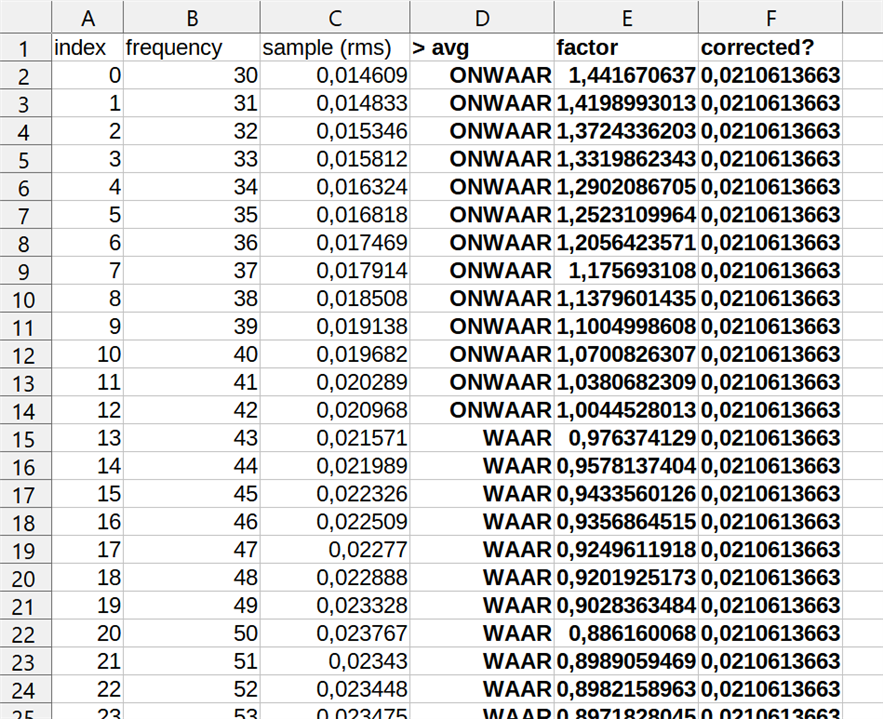
Column E is the correction factor per frequency. Calculated by dividing average by actual measurement. I'm now trying to create a flow that can read this info and adapt the input. Then check if this gives a flatter curve between 30 and 130 Hz. Average gRMS accross the range turns out to be 0.0210613663366337. Where the measured acceleration is above the average, the correction factor is < 0. When below average, it's > 0. In this initial exercise, I'm going to multiply the set VPP with the factor for each frequency.
I'm writing this blog as I try this, so it's a real-time record of failure or success.
To Do: make the flow with correction mechanism, sweep and look at the output. Will it be linear?
Exercise done. The results are good. This the output of the sensor for 30 - 130 Hz, where I compensated the shaker's input at each frequency. I used the factors calculated above
For reference, this is how the same measurement looks like without compensation:
LabVIEW flow changes for compensation
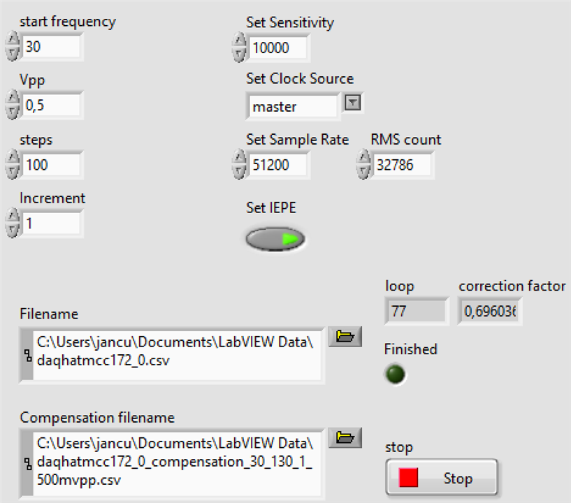
The front panel has a few controls more. A file selector for the spreadsheet with compensation values, and an indicator of the current correction factor that's applied to the jig's input signal:
Read Compensation Spreadsheet in Array
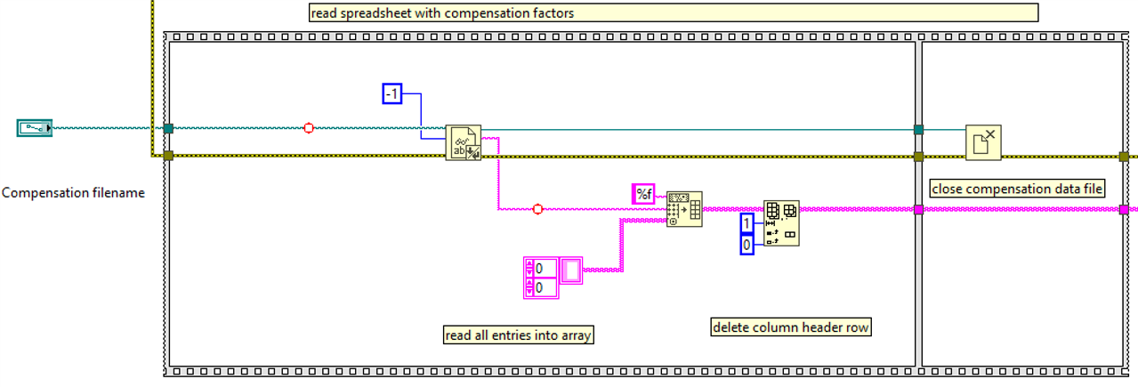
At the start of the flow, while instruments are initialised, the compensation spreadsheet is read into an array. The file is closed, because not needed anymore. The loop will retrieve the correct compensation factor from the array.
Apply Compensation
Inside the sweep loop, at each step, the compensation value is read from the array, and applied to the shaker's input signal amplitude.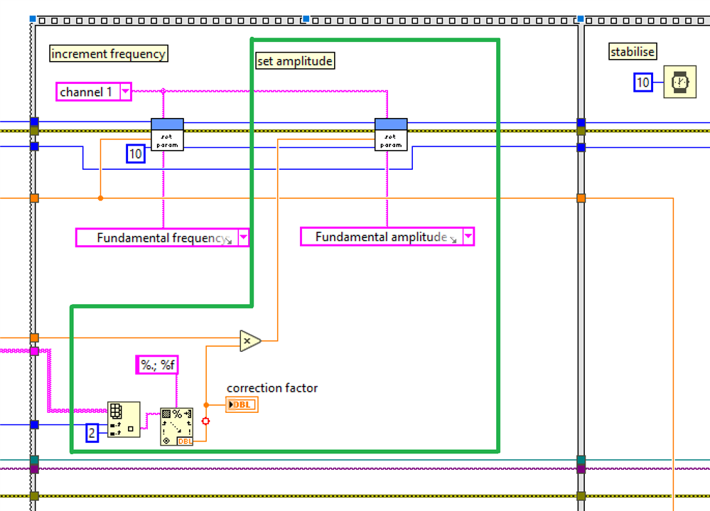
The flow is expecting that the right conversion factor appears in sync in the spreadsheet. If you between 30 and 40 Hz, in steps of 1 Hz, the spreadsheet should have records for 30, 31, 32 ... in sequence. A future function could be a lookup based on active frequency, but I'm not planning for that now.
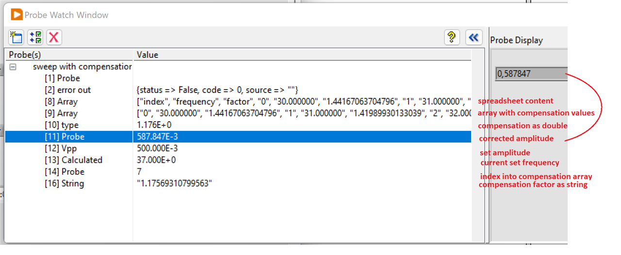
An action shot of the variables of the flow at a given frequency in the sweep (37 Hz):