element14 Community
element14 Community
    Register Log In
  • Site
  • Search
  • Log In Register
  • Community Hub
    Community Hub
    • What's New on element14
    • Feedback and Support
    • Benefits of Membership
    • Personal Blogs
    • Members Area
    • Achievement Levels
  • Learn
    Learn
    • Ask an Expert
    • eBooks
    • element14 presents
    • Learning Center
    • Tech Spotlight
    • STEM Academy
    • Webinars, Training and Events
    • Learning Groups
  • Technologies
    Technologies
    • 3D Printing
    • FPGA
    • Industrial Automation
    • Internet of Things
    • Power & Energy
    • Sensors
    • Technology Groups
  • Challenges & Projects
    Challenges & Projects
    • Design Challenges
    • element14 presents Projects
    • Project14
    • Arduino Projects
    • Raspberry Pi Projects
    • Project Groups
  • Products
    Products
    • Arduino
    • Avnet Boards Community
    • Dev Tools
    • Manufacturers
    • Multicomp Pro
    • Product Groups
    • Raspberry Pi
    • RoadTests & Reviews
  • Store
    Store
    • Visit Your Store
    • Choose another store...
      • Europe
      •  Austria (German)
      •  Belgium (Dutch, French)
      •  Bulgaria (Bulgarian)
      •  Czech Republic (Czech)
      •  Denmark (Danish)
      •  Estonia (Estonian)
      •  Finland (Finnish)
      •  France (French)
      •  Germany (German)
      •  Hungary (Hungarian)
      •  Ireland
      •  Israel
      •  Italy (Italian)
      •  Latvia (Latvian)
      •  
      •  Lithuania (Lithuanian)
      •  Netherlands (Dutch)
      •  Norway (Norwegian)
      •  Poland (Polish)
      •  Portugal (Portuguese)
      •  Romania (Romanian)
      •  Russia (Russian)
      •  Slovakia (Slovak)
      •  Slovenia (Slovenian)
      •  Spain (Spanish)
      •  Sweden (Swedish)
      •  Switzerland(German, French)
      •  Turkey (Turkish)
      •  United Kingdom
      • Asia Pacific
      •  Australia
      •  China
      •  Hong Kong
      •  India
      •  Korea (Korean)
      •  Malaysia
      •  New Zealand
      •  Philippines
      •  Singapore
      •  Taiwan
      •  Thailand (Thai)
      • Americas
      •  Brazil (Portuguese)
      •  Canada
      •  Mexico (Spanish)
      •  United States
      Can't find the country/region you're looking for? Visit our export site or find a local distributor.
  • Translate
  • Profile
  • Settings
Test & Tools
  • Technologies
  • More
Test & Tools
Forum Polarity Sense Circuit
  • Blog
  • Forum
  • Documents
  • Files
  • Members
  • Mentions
  • Sub-Groups
  • Tags
  • More
  • Cancel
  • New
Join Test & Tools to participate - click to join for free!
Actions
  • Share
  • More
  • Cancel
Forum Thread Details
  • State Suggested Answer
  • Replies 20 replies
  • Answers 1 answer
  • Subscribers 354 subscribers
  • Views 4967 views
  • Users 0 members are here
  • reverse_polarity_sensor
Related

Polarity Sense Circuit

jw0752
jw0752 over 9 years ago

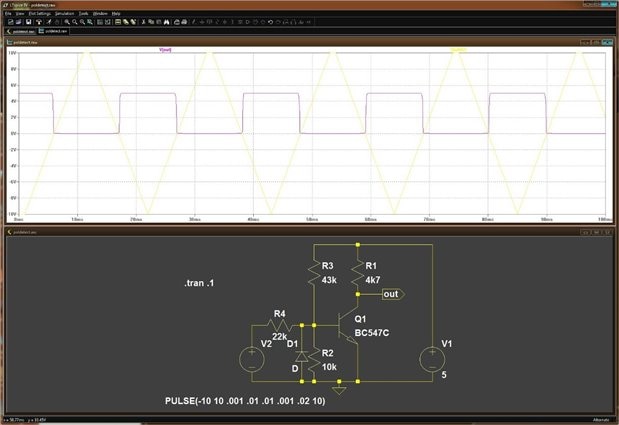
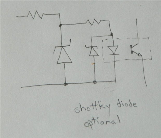
In one of my recent builds it was necessary to come up with a circuit that would sense if the inputs were hooked up reverse polarity. I came up with this circuit:


image

I have tested this circuit to 100 volts DC on its Test Input terminals. If the Test Inputs are under normal polarity the output is LOW and if the Test Inputs are under reverse polarity the Output is HIGH. Unfortunately the Test Inputs will not sense a reversed polarity below 3.5 Volts. While these limitations were not a problem for my build I am curious if there are other better circuits to test polarity than what I cooked up here. Also if you see problems with the circuit above any critique would be appreciated. R1 limits the forward current through LED1 which acts like a zener and keeps the voltage Gate to Drain from exceeding breakdown limits. D1 is reverse biased under proper polarity. R2 keeps the P CH MOSFET off until there is a Negative Voltage applied at the gate by a reversed Test Input polarity.


Thanks John

  • Sign in to reply
  • Cancel

Top Replies

  • johnbeetem
    johnbeetem over 9 years ago +2
    I don't know what your application is for this polarity sense circuit, but if you're worried about DC power inputs being hooked up incorrectly you might consider using a Schottky Diode Bridge for your…
  • shabaz
    shabaz over 9 years ago in reply to jw0752 +2
    Hi John, I once took apart a very old touch tone phone (probably a trimline), it was interesting to see that they used analog tone generation circuitry! using pot core wound transformers for the tone generation…
  • Robert Peter Oakes
    Robert Peter Oakes over 9 years ago +1
    without an OP-Amp or other transistor your limited by the Diode voltages and also the VGS Threshold of the FET so without making it much more complex it seems you hae a good solution or what you needed…
  • Robert Peter Oakes
    0 Robert Peter Oakes over 9 years ago

    without an OP-Amp or other transistor your limited by the Diode voltages and also the VGS Threshold of the FET so without making it much more complex it seems you hae a good solution or what you needed, A logic level FET may improve things a bit

    Peter

    • Cancel
    • Vote Up +1 Vote Down
    • Sign in to reply
    • Verify Answer
    • Cancel
  • jw0752
    0 jw0752 over 9 years ago in reply to Robert Peter Oakes

    I hadn't thought about a logic level FET. I bet that would bring me down another volt or two. I will have to order one up as I only have them in N channel.

    Thanks John

    • Cancel
    • Vote Up 0 Vote Down
    • Sign in to reply
    • Verify Answer
    • Cancel
  • michaelkellett
    0 michaelkellett over 9 years ago in reply to jw0752

    How about this:


    image

    You can tune R4 to get the threshold in the right place - it won't be that stable because it depends on Q1 Vbe and gain and stuff which are temperature dependent.  You could use a single rail comparator chip with rail to rail input capability.


    MK

    • Cancel
    • Vote Up +1 Vote Down
    • Sign in to reply
    • Verify Answer
    • Reject Answer
    • Cancel
  • D_Hersey
    0 D_Hersey over 9 years ago

    Why not use an opto-isolator?  You could shunt the input diode with a reversed signal diode. 

    • Cancel
    • Vote Up 0 Vote Down
    • Sign in to reply
    • Verify Answer
    • Cancel
  • jw0752
    0 jw0752 over 9 years ago in reply to michaelkellett

    Hi Michael,

    I will breadboard the circuit tonight and play around with it to see what it will do. Thank you for the nice suggestion.

    John

    • Cancel
    • Vote Up 0 Vote Down
    • Sign in to reply
    • Verify Answer
    • Cancel
  • jw0752
    0 jw0752 over 9 years ago in reply to D_Hersey

    Hi Don,

    I actually tried to get an opto-isolator to work. It was doing the job but I could not get it to work over a wide input voltage range. It might be that a better selection of components would have fixed the limits. The opto-isolator I was using had a 1.7V max 20 mA LED. I put diodes in parallel with the OI's LED to shunt current when the voltage exceeded the 1.7 volts and as I mentioned it was working but if I had it current limited for any reasonable voltage level ( think 30 V) then there would not be enough current to turn on the LED of the OI at 5 volts and lower. In any case I will probably revisit the idea and do some more experiments. Thanks for your idea and input.

    John

    • Cancel
    • Vote Up 0 Vote Down
    • Sign in to reply
    • Verify Answer
    • Cancel
  • johnbeetem
    0 johnbeetem over 9 years ago

    Sounds like a good use for a spare LM339 comparator image: http://www.element14.com/community/message/157410/l/lm-339-comparator-question#157410


    The best polarity-sense circuit for this depends a lot on how much input impedance you want on the test inputs.  If you'd like them to be high-impedance, a comparator IC is a good way to go.  If you need electrical isolation and don't mind a high current draw, then an opto-isolator is good.

    • Cancel
    • Vote Up 0 Vote Down
    • Sign in to reply
    • Verify Answer
    • Cancel
  • Robert Peter Oakes
    0 Robert Peter Oakes over 9 years ago

    so a few ground rules


    No Battery ??

    minimal load on circuit...


    any more ?

    • Cancel
    • Vote Up 0 Vote Down
    • Sign in to reply
    • Verify Answer
    • Cancel
  • mcb1
    0 mcb1 over 9 years ago

    John

    The question I would ask is "What are the Inputs"


    If you are trying to ensure your battery discharger is correctly connected, then the loading of the inputs are fine.

    However if its something high impedance then its possibly going to drag the inputs down.


    It's a very interesting issue, and the only other thought I have is a DC-DC inverter chip.

    They have a wide range at the bottom end (from 0.7v), but might struggle at the upper end.

    It could allow a two fold approach ... something for the bottom and something for the higher voltages.


    The best I saw for a 12v system was a diode feeding the coil of a relay, and the contacts applied the voltage if it was correctly connected.


    Mark

    • Cancel
    • Vote Up +1 Vote Down
    • Sign in to reply
    • Verify Answer
    • Cancel
  • D_Hersey
    0 D_Hersey over 9 years ago

    There are a few ways to go with that one, John.  As I understand it, you want a sensitive circuit, but you want it to not be vulnerable to overload.  The simplest thing to do is clamp your input with a backward Zener and a resistor.  image

    • Cancel
    • Vote Up +1 Vote Down
    • Sign in to reply
    • Verify Answer
    • Cancel
>
element14 Community

element14 is the first online community specifically for engineers. Connect with your peers and get expert answers to your questions.

  • Members
  • Learn
  • Technologies
  • Challenges & Projects
  • Products
  • Store
  • About Us
  • Feedback & Support
  • FAQs
  • Terms of Use
  • Privacy Policy
  • Legal and Copyright Notices
  • Sitemap
  • Cookies

An Avnet Company © 2025 Premier Farnell Limited. All Rights Reserved.

Premier Farnell Ltd, registered in England and Wales (no 00876412), registered office: Farnell House, Forge Lane, Leeds LS12 2NE.

ICP 备案号 10220084.

Follow element14

  • X
  • Facebook
  • linkedin
  • YouTube