element14 Community
element14 Community
    Register Log In
  • Site
  • Search
  • Log In Register
  • About Us
  • Community Hub
    Community Hub
    • What's New on element14
    • Feedback and Support
    • Benefits of Membership
    • Personal Blogs
    • Members Area
    • Achievement Levels
  • Learn
    Learn
    • Ask an Expert
    • eBooks
    • element14 presents
    • Learning Center
    • Tech Spotlight
    • STEM Academy
    • Webinars, Training and Events
    • Learning Groups
  • Technologies
    Technologies
    • 3D Printing
    • FPGA
    • Industrial Automation
    • Internet of Things
    • Power & Energy
    • Sensors
    • Technology Groups
  • Challenges & Projects
    Challenges & Projects
    • Design Challenges
    • element14 presents Projects
    • Project14
    • Arduino Projects
    • Raspberry Pi Projects
    • Project Groups
  • Products
    Products
    • Arduino
    • Avnet Boards Community
    • Dev Tools
    • Manufacturers
    • Multicomp Pro
    • Product Groups
    • Raspberry Pi
    • RoadTests & Reviews
  • Store
    Store
    • Visit Your Store
    • Choose another store...
      • Europe
      •  Austria (German)
      •  Belgium (Dutch, French)
      •  Bulgaria (Bulgarian)
      •  Czech Republic (Czech)
      •  Denmark (Danish)
      •  Estonia (Estonian)
      •  Finland (Finnish)
      •  France (French)
      •  Germany (German)
      •  Hungary (Hungarian)
      •  Ireland
      •  Israel
      •  Italy (Italian)
      •  Latvia (Latvian)
      •  
      •  Lithuania (Lithuanian)
      •  Netherlands (Dutch)
      •  Norway (Norwegian)
      •  Poland (Polish)
      •  Portugal (Portuguese)
      •  Romania (Romanian)
      •  Russia (Russian)
      •  Slovakia (Slovak)
      •  Slovenia (Slovenian)
      •  Spain (Spanish)
      •  Sweden (Swedish)
      •  Switzerland(German, French)
      •  Turkey (Turkish)
      •  United Kingdom
      • Asia Pacific
      •  Australia
      •  China
      •  Hong Kong
      •  India
      •  Korea (Korean)
      •  Malaysia
      •  New Zealand
      •  Philippines
      •  Singapore
      •  Taiwan
      •  Thailand (Thai)
      • Americas
      •  Brazil (Portuguese)
      •  Canada
      •  Mexico (Spanish)
      •  United States
      Can't find the country/region you're looking for? Visit our export site or find a local distributor.
  • Translate
  • Profile
  • Settings
Test & Tools
  • Technologies
  • More
Test & Tools
Forum Ti LDC1000EVM A Question on Inductance
  • Blog
  • Forum
  • Documents
  • Files
  • Members
  • Mentions
  • Sub-Groups
  • Tags
  • More
  • Cancel
  • New
Join Test & Tools to participate - click to join for free!
Actions
  • Share
  • More
  • Cancel
Forum Thread Details
  • State Verified Answer
  • Replies 24 replies
  • Answers 2 answers
  • Subscribers 358 subscribers
  • Views 5874 views
  • Users 0 members are here
  • ldc1000evm
  • inductors
Related

Ti LDC1000EVM A Question on Inductance

jw0752
jw0752 over 9 years ago

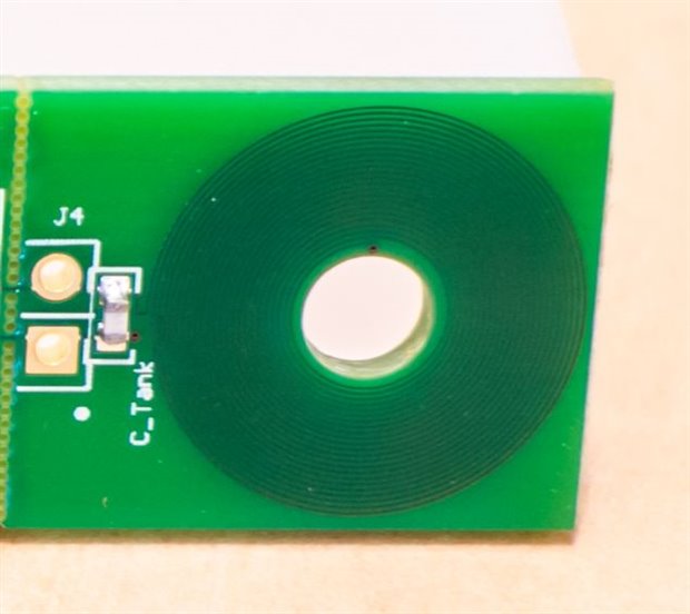
Inspired by shabaz I purchased a TI  LDC1000EVMLDC1000EVM Evaluation Kit and set it up If you want more information on the kit itself check out Shabaz's blog as it is very interesting Getting Started with the LDC1000 - Small Metal Detection!


After setting up the board I wanted to confirm some of the things I thought I understood about inductors and so I performed a couple of experiments and my results leave me with a question that I am hoping you can help me with.


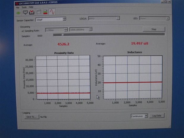
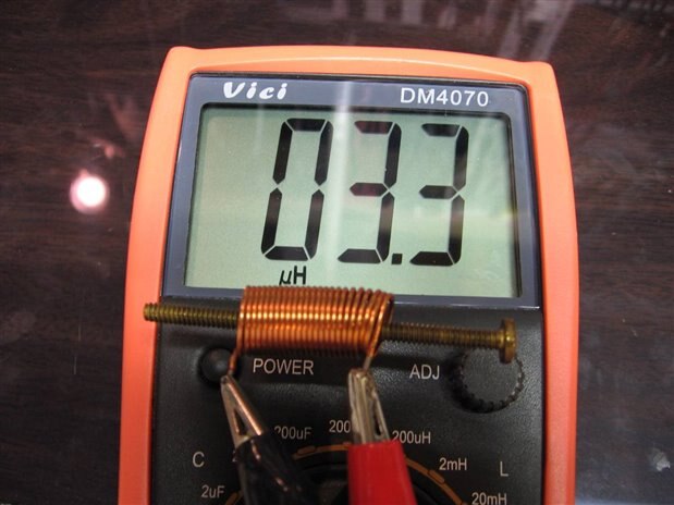
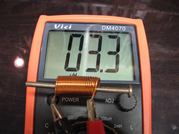
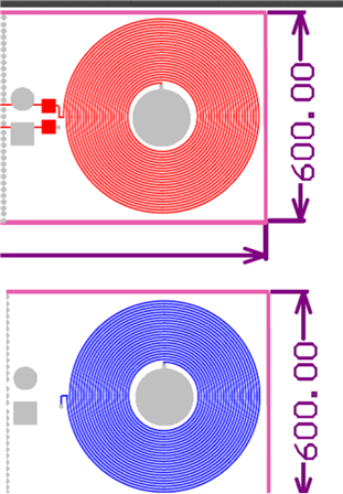
My first experiment was to look at the inductor in free air.


image


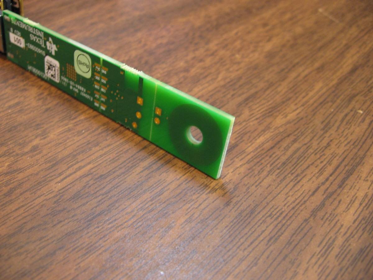
The GUI for the Evaluation board was reading 19.496 uH with an open air core.


image


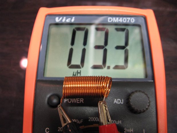
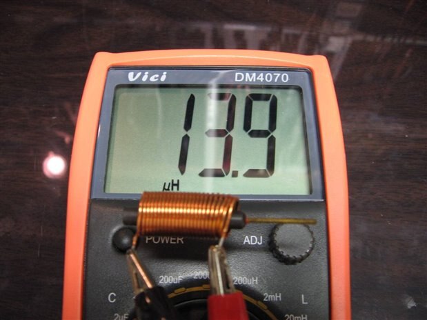
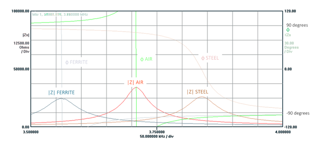
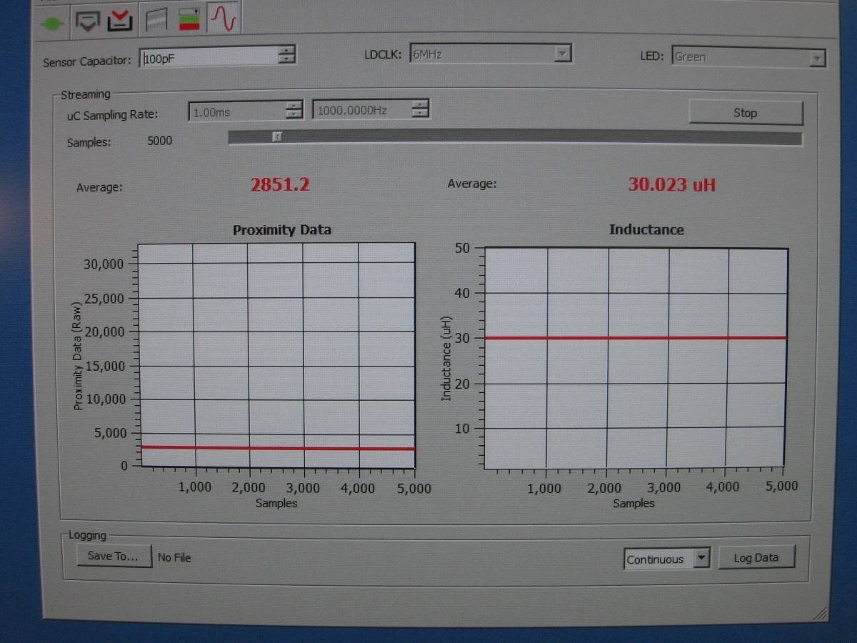
For my next experiment I inserted a small ferrite core into the inductor.


image


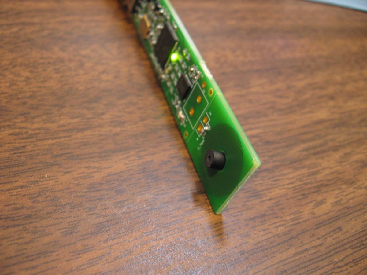
My expectation was that this ferrite core would increase the inductance of the coil. I was not disappointed as the inductance rose to 30 uH.


image


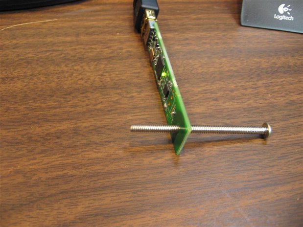
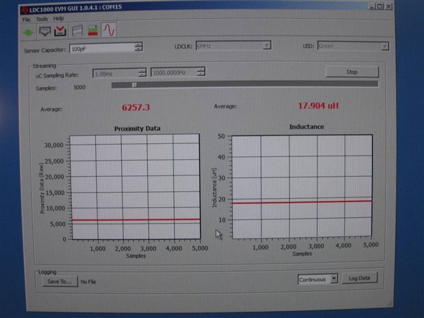
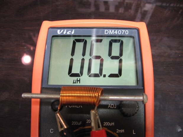
My next experiment was to replace the ferrite core with a soft steel rod of similar length to the ferrite one.


image


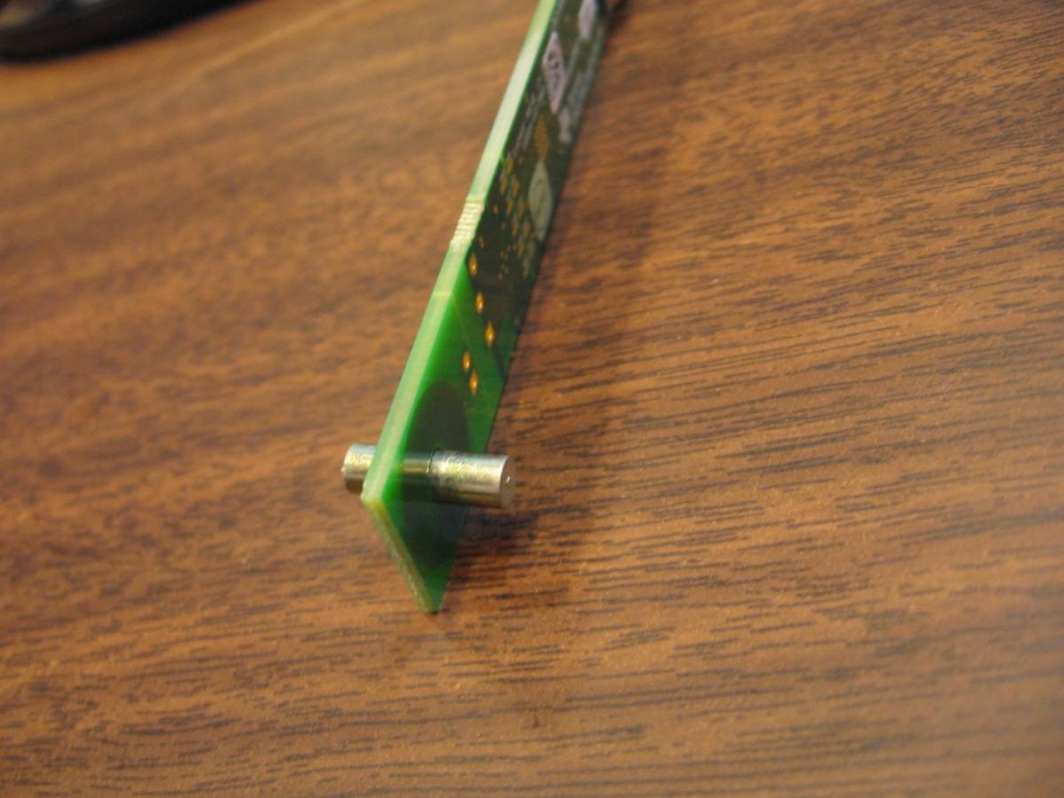
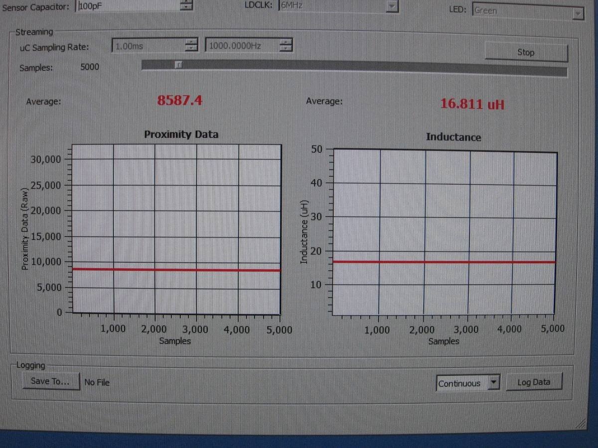
To my surprise and confusion the inductance of the coil dropped to 16.811 uH which was almost 3 uH lower than open air. I am hoping that someone can explain this behavior to me. I did not expect the steel core to do as well as the ferrite but I did expect it to do better than open air.


image


I have my physics book open right now and I am reviewing inductors to see if I can better understand why a steel core would lower the inductance of a coil instead of raising it.


John

  • Sign in to reply
  • Cancel

Top Replies

  • shabaz
    shabaz over 9 years ago in reply to jw0752 +3
    I snapped off that resonant circuit and applied it to the VNA, this is the result I get (it could be inaccurate, the VNA is freshly built and could have issues. I'm still learning how to use it). I've…
  • DAB
    DAB over 9 years ago +2
    Hi John, After reading your post I remembered something I wrote in my book about how the crystalline structure of iron behaves under a magnetic field. The ferrite core is a very homogeneous material, so…
  • shabaz
    shabaz over 9 years ago +2 verified
    Hi John and Everyone, Chris Oberhauser from TI replied : At the higher frequencies (>500kHz) that LDC devices typically operate, the eddy currents on the target surface overwhelm the permeability and…
Parents
  • michaelwylie
    0 michaelwylie over 9 years ago

    John;


    Any chance that it's stainless steel?

    • Cancel
    • Vote Up 0 Vote Down
    • Sign in to reply
    • Verify Answer
    • Cancel
  • jw0752
    0 jw0752 over 9 years ago in reply to michaelwylie

    Hi Michael,

    I set up the LDC1000 EVM again so that I could see the effect of a Stainless Steel core. As a reminder here is a screen shot of the GUI with an air core:


    image


    We begin with 19.497 uH in air. Now I will put a stainless steel screw through the coil.


    image


    Here is a screen shot of the GUI with the change as affected by the SS screw:


    image


    We are seeing an indicated decrease in the inductance though it is only a 1.5 uH decrease which is about half that was encountered with the soft steel core. The experiment that I did at the end of this section would indicate that we should not be seeing any change in the  inductance as the SS Screw is paramagnetic and should not affect the inductance.


    As a side I did a little research and I learned that not all stainless steel grades are paramagnetic. The screw that I used for this experiment was paramagnetic but apparently there are exceptions. Here is a short article about magnetic permeability in stainless steel.


    http://www.azom.com/article.aspx?ArticleID=1140


    For the fun of it I hooked up a small inductor and measured it with my Cheap LCR meter. Then I put a brass screw, a stainless steel screw, a steel screw, and finally a ferrite inductor core, into the coil to see what effect they each would have.


    image

    Base line open air core 3.3 uH coil.


    image


    Brass screw with no magnetic permeability has no effect on the coils inductance.


    image


    Stainless screw with no magnetic permeability also has no effect on the inductance.


    image


    Ferromagnetic steel screw causes the inductance to more than double to 6.9 uH


    image


    Small Ferrite core causes the inductance to quadruple to 13.9 uH


    Remember that the ferrite when used with the LDC 1000 EVM also caused the GUI to show an increase in the inductance of the test coil but the steel core had the opposite effect.


    John

    • Cancel
    • Vote Up +1 Vote Down
    • Sign in to reply
    • Verify Answer
    • Cancel
Reply
  • jw0752
    0 jw0752 over 9 years ago in reply to michaelwylie

    Hi Michael,

    I set up the LDC1000 EVM again so that I could see the effect of a Stainless Steel core. As a reminder here is a screen shot of the GUI with an air core:


    image


    We begin with 19.497 uH in air. Now I will put a stainless steel screw through the coil.


    image


    Here is a screen shot of the GUI with the change as affected by the SS screw:


    image


    We are seeing an indicated decrease in the inductance though it is only a 1.5 uH decrease which is about half that was encountered with the soft steel core. The experiment that I did at the end of this section would indicate that we should not be seeing any change in the  inductance as the SS Screw is paramagnetic and should not affect the inductance.


    As a side I did a little research and I learned that not all stainless steel grades are paramagnetic. The screw that I used for this experiment was paramagnetic but apparently there are exceptions. Here is a short article about magnetic permeability in stainless steel.


    http://www.azom.com/article.aspx?ArticleID=1140


    For the fun of it I hooked up a small inductor and measured it with my Cheap LCR meter. Then I put a brass screw, a stainless steel screw, a steel screw, and finally a ferrite inductor core, into the coil to see what effect they each would have.


    image

    Base line open air core 3.3 uH coil.


    image


    Brass screw with no magnetic permeability has no effect on the coils inductance.


    image


    Stainless screw with no magnetic permeability also has no effect on the inductance.


    image


    Ferromagnetic steel screw causes the inductance to more than double to 6.9 uH


    image


    Small Ferrite core causes the inductance to quadruple to 13.9 uH


    Remember that the ferrite when used with the LDC 1000 EVM also caused the GUI to show an increase in the inductance of the test coil but the steel core had the opposite effect.


    John

    • Cancel
    • Vote Up +1 Vote Down
    • Sign in to reply
    • Verify Answer
    • Cancel
Children
  • michaelwylie
    0 michaelwylie over 9 years ago in reply to jw0752

    I looked into the design of the coil on the sensor board:

    image


    This isn't what I would exactly call a standard coil. The coil you are comparing to on your "cheapy" meter is a different architecture. Try winding a coil in a spiral and measuring the inductance with and without the steel core?

    • Cancel
    • Vote Up 0 Vote Down
    • Sign in to reply
    • Verify Answer
    • Cancel
  • jw0752
    0 jw0752 over 9 years ago in reply to michaelwylie

    Yes you are correct the architecture is different. Incidentally now that I am getting into the data sheet it is becoming clear that the design is for sensing a distance between the coil and a conductive plate. The coil induces eddy currents in the conductive plate and then senses the distance to the conductive plate by the counter EMF that eddy currents create in the coil. I believe that the inductance of the coil as measured by the LDC 1000 will be quite accurate as long as the conductive plate is used. When I started putting different metals through the center of the coil I was outside the design parameters of the device.


    You suggested that I create a coil with a spiral architecture and rerun my tests on the cheap LCR meter. I have no doubt that a change in architecture will change the inductance and even if I can wind a spiral that starts at 3.3 uH it will not react to the same degree as the linear coil that I used. However the basic physics should still hold. The Brass and the Stainless with not change the open air value. The steel will have an effect to increase the inductance and the ferrite will have the greatest effect to increase the inductance. What results would you predict for this experiment?


    I hope all is well in CA. Watching the News makes me wonder if I should return in January or not. I hope all is well with the family.

    John

    • Cancel
    • Vote Up 0 Vote Down
    • Sign in to reply
    • Verify Answer
    • Cancel
  • michaelwylie
    0 michaelwylie over 9 years ago in reply to jw0752

    After some reading, this spiral inductor should have it's inductance increasing with a higher permeability core. It's gotta be something else. I started a new job in August, so now I'm living in Los Angeles (Panorama City).

    • Cancel
    • Vote Up 0 Vote Down
    • Sign in to reply
    • Verify Answer
    • Cancel
  • jw0752
    0 jw0752 over 9 years ago in reply to michaelwylie

    Hi Michael,

    Congratulations on the new job. Panorama City is only 25 miles from Torrance on the 405. If I decide to come out in January we could try to get together and discuss electronics if you have time this year.

    John

    • Cancel
    • Vote Up 0 Vote Down
    • Sign in to reply
    • Verify Answer
    • Cancel
  • michaelwylie
    0 michaelwylie over 9 years ago in reply to jw0752

    I would look forward to that very much image

    • Cancel
    • Vote Up 0 Vote Down
    • Sign in to reply
    • Verify Answer
    • Cancel
  • shabaz
    0 shabaz over 9 years ago in reply to jw0752

    I snapped off that resonant circuit and applied it to the VNA, this is the result I get (it could be inaccurate, the VNA is freshly built and could have issues. I'm still learning how to use it).

    I've overlaid the results for the resonant circuit with it's air core, and then with ferrite placed close to it, and also with a (guessing it is steel) M4x6 pan head screw placed close to it.

    All the time taking care not to move or change anything else.


    image

    It is very interesting. As expected, the ferrite increased the inductance, and the Q dropped too (but very slightly). We can see the inductance increased because the resonant frequency has reduced (from about 3.71MHz in air [peak of the red curve], to 3.56MHz with the ferrite [peak of the blue curve]).

    With the steel screw however, the resonant frequency increased (to 3.84MHz [peak of the brown curve]). I can't explain it : (  But I'm no expert on inductors nor cores!

    And again the Q decreased slightly (as expected - I think anything placed close to that fixed number of turns will decrease Q).


    Hi Charles gervasi do you know what is going on? Or is this something that needs simulation to analyze? It looks like magnetic flux density dropped when the steel was close to the spiral (I didn't place it inside, just close to it).

    The inductor in this circuit is a spiral trace on two sides of this PCB (LDC1000 eval board), the photo below shows what it looks like:

    image


    Basically, I did a reflection measurement, I'll post a photo of the testbed later today.


    Thanks!

    • Cancel
    • Vote Up +3 Vote Down
    • Sign in to reply
    • Verify Answer
    • Cancel
  • gervasi
    0 gervasi over 9 years ago in reply to shabaz

    " We can see the inductance increased because the resonant frequency has reduced (from about 3.71MHz in air [peak of the red curve], to 3.56MHz with the ferrite [peak of the blue curve])."

    I do not know what's happening, why the resonant frequency is going up with steel.  I've never experimented with this stuff.


    My only thought is that the lower resonant frequency does not necessarily mean increased inductance.  I see increased inductance as appearing in the higher Z at lower frequencies.  My crude understanding is the inductance peaks at the resonant frequency because of the effects of the unwanted capacitance of the inductor beginning to predominate over the desired inductance. 


    It's suprising to me, although I've never experimented with this, that the resonant frequencies are all clustered in the 3.5MHz range. 


    I wonder if the issue is core losses acting as a short as in this diagram from Trilogy of Inductors:

    image

    • Cancel
    • Vote Up 0 Vote Down
    • Sign in to reply
    • Verify Answer
    • Cancel
  • shabaz
    0 shabaz over 9 years ago in reply to gervasi

    Hi Charles,

    Thanks for examining it!

    Regarding the 3.5MHz range, sorry it may not have been clear, but there is a 100pF cap on that board, so the analysis was of the complete resonant circuit (LC tank), not just the coil.

    I'm thinking, maybe we should also ask TI, since they had the tools to design the inductor in the first place.

    I'll post the question on their forum, to see what they respond with.


    Unrelated, I also found this low-cost set of metals (it is only six metals, but at least they are all the same size) http://shop.miniscience.com/navigation/detail.asp?id=METCYLSET6

    that may be useful for experimenting with the LDC1000.

    • Cancel
    • Vote Up +1 Vote Down
    • Sign in to reply
    • Verify Answer
    • Cancel
element14 Community

element14 is the first online community specifically for engineers. Connect with your peers and get expert answers to your questions.

  • Members
  • Learn
  • Technologies
  • Challenges & Projects
  • Products
  • Store
  • About Us
  • Feedback & Support
  • FAQs
  • Terms of Use
  • Privacy Policy
  • Legal and Copyright Notices
  • Sitemap
  • Cookies

An Avnet Company © 2025 Premier Farnell Limited. All Rights Reserved.

Premier Farnell Ltd, registered in England and Wales (no 00876412), registered office: Farnell House, Forge Lane, Leeds LS12 2NE.

ICP 备案号 10220084.

Follow element14

  • X
  • Facebook
  • linkedin
  • YouTube