element14 Community
element14 Community
    Register Log In
  • Site
  • Search
  • Log In Register
  • About Us
  • Community Hub
    Community Hub
    • What's New on element14
    • Feedback and Support
    • Benefits of Membership
    • Personal Blogs
    • Members Area
    • Achievement Levels
  • Learn
    Learn
    • Ask an Expert
    • eBooks
    • element14 presents
    • Learning Center
    • Tech Spotlight
    • STEM Academy
    • Webinars, Training and Events
    • Learning Groups
  • Technologies
    Technologies
    • 3D Printing
    • FPGA
    • Industrial Automation
    • Internet of Things
    • Power & Energy
    • Sensors
    • Technology Groups
  • Challenges & Projects
    Challenges & Projects
    • Design Challenges
    • element14 presents Projects
    • Project14
    • Arduino Projects
    • Raspberry Pi Projects
    • Project Groups
  • Products
    Products
    • Arduino
    • Avnet Boards Community
    • Dev Tools
    • Manufacturers
    • Multicomp Pro
    • Product Groups
    • Raspberry Pi
    • RoadTests & Reviews
  • Store
    Store
    • Visit Your Store
    • Choose another store...
      • Europe
      •  Austria (German)
      •  Belgium (Dutch, French)
      •  Bulgaria (Bulgarian)
      •  Czech Republic (Czech)
      •  Denmark (Danish)
      •  Estonia (Estonian)
      •  Finland (Finnish)
      •  France (French)
      •  Germany (German)
      •  Hungary (Hungarian)
      •  Ireland
      •  Israel
      •  Italy (Italian)
      •  Latvia (Latvian)
      •  
      •  Lithuania (Lithuanian)
      •  Netherlands (Dutch)
      •  Norway (Norwegian)
      •  Poland (Polish)
      •  Portugal (Portuguese)
      •  Romania (Romanian)
      •  Russia (Russian)
      •  Slovakia (Slovak)
      •  Slovenia (Slovenian)
      •  Spain (Spanish)
      •  Sweden (Swedish)
      •  Switzerland(German, French)
      •  Turkey (Turkish)
      •  United Kingdom
      • Asia Pacific
      •  Australia
      •  China
      •  Hong Kong
      •  India
      •  Korea (Korean)
      •  Malaysia
      •  New Zealand
      •  Philippines
      •  Singapore
      •  Taiwan
      •  Thailand (Thai)
      • Americas
      •  Brazil (Portuguese)
      •  Canada
      •  Mexico (Spanish)
      •  United States
      Can't find the country/region you're looking for? Visit our export site or find a local distributor.
  • Translate
  • Profile
  • Settings
Test & Tools
  • Technologies
  • More
Test & Tools
Forum MULTICOMP PRO MP750065 Function Generator - Programming Pt2: LabVIEW tryout (a)
  • Blog
  • Forum
  • Documents
  • Files
  • Members
  • Mentions
  • Sub-Groups
  • Tags
  • More
  • Cancel
  • New
Join Test & Tools to participate - click to join for free!
Actions
  • Share
  • More
  • Cancel
Forum Thread Details
  • Replies 5 replies
  • Subscribers 357 subscribers
  • Views 2545 views
  • Users 0 members are here
  • MP750065
  • function_generator
  • labview
  • scpi
Related

MULTICOMP PRO MP750065 Function Generator - Programming Pt2: LabVIEW tryout (a)

Jan Cumps
Jan Cumps over 3 years ago

The 2nd post in this Program the Device series talks about initial LabVIEW integration. An unstructured test to see if I can set up a meaningful conversation with the instrument.
It's the follow up of Programming Pt1: SDK Demo.
For the MP750668, UTG900C-II, UTG1010 owners: this will very likely work for you too.

image
image: the functional flow. Click to enlarge

In this post I'll open a session with the instrument, set the frequency, read the current frequency back and close the session. The interaction is via UNI-T's UCI api and dll. 

In a next post, I'll break this flow up in the traditional LabVIEW Virual Instrument blocks (Init, Close, basic Read and Write, and some advanced blocks to set and get favourite values, e.g. Set Freq, Get Freq, Set Waveform, ...)

Integration with UNI-T UCI API and DLL

The programmer's guide for the instrument is for the UCI api. This is  available as a dll in the SDK kit I used in the previous post.
In LabVIEW, you can call dll functions. In this example, I use these:

  • uci_Open()
  • uci_WriteSimple()
  • uci_ReadX()
  • uci_Close()

LabVIEW has a wizard to inspect a dll and create building blocks for you. For that, you need the dll and the accompanying .h file.
These files are part of the UNI-T SDK, but the wizard failed when I tried it. It runs forever without returning.
Luckily, there's a 2nd option: define the function declarations manually. You place a Call Library Function block on the LabVIEW canvas, and configure it as needed.
In this blog, I will show one block as example. In a later blog, where I structure the flow in functional components, I'll review all used functions.

Example: uci_open()

Start by reading the Programming Help, and have the ucidef.h file ready. Both available in the SDK.
The function has this signature:

image
image: UCI Help Document snippet showing the function signature

The custom types are defined in ucidef.h - you can see the base types there.
I'm posting the relevant ones here:

#define u_tchar char
#define u_status u_int32
#define u_size u_uint32
#define u_session u_uint32
#define u_string u_tchar*


This is what uci_Open looks like in LabVIEW's definition
uint32_t uci_Open(CStr _addr, uint32_t *_session, uint32_t _timeOut);

You define that by configuring the Call Library Function block. First you select the dll and function. Also configure call settings.

image
image: set the main function attributes

Then you configure the return value and each parameter. Translate the UCI types to LabVIEW's base types.

image
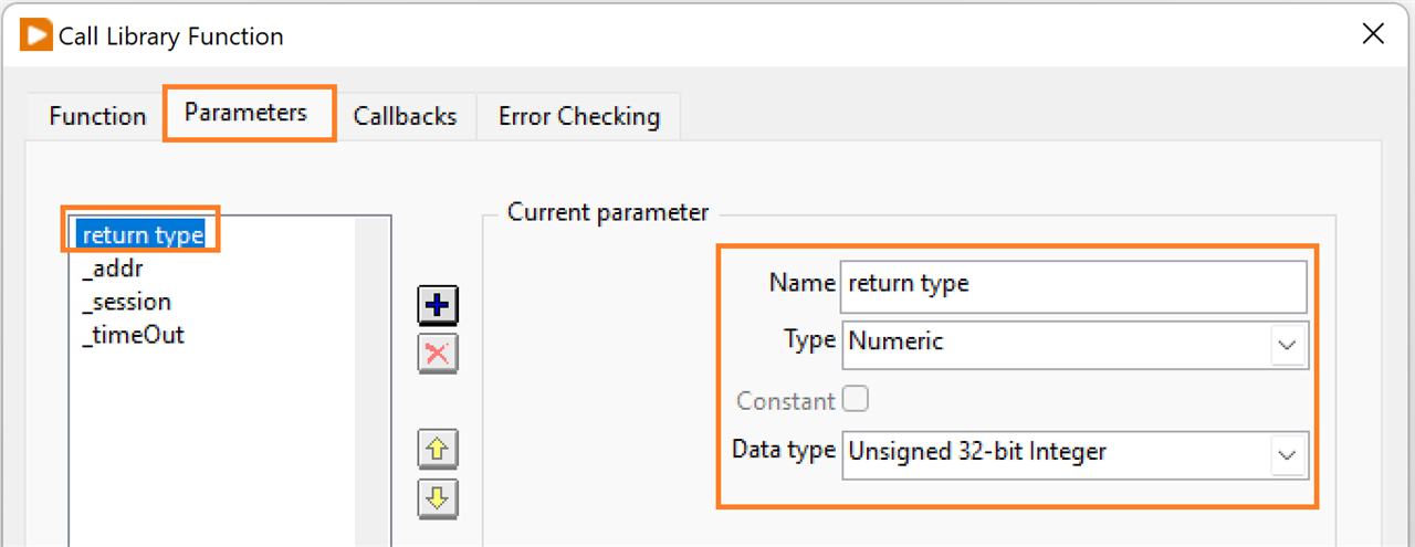
image: define return value signature

image
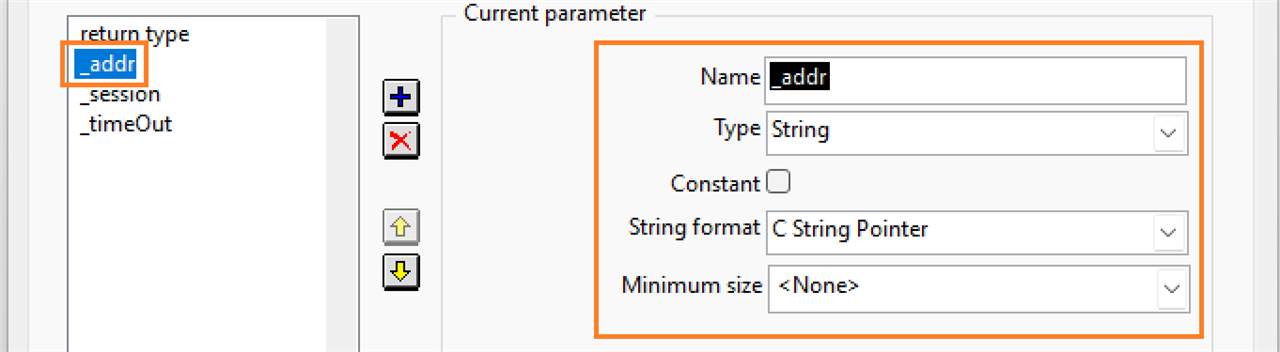
image: 1st parameter

The session parameter is an output, changed by the dll. That means you have to pass by reference.

image
image: 2nd parameter. Passed by value because it's an output parameter

image
image: last parameter

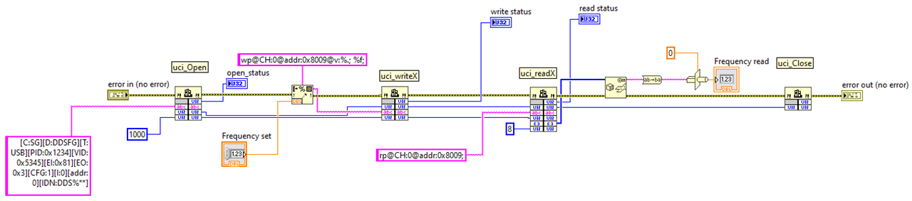
Full LabVIEW Flow (part a)

You can see the full process in the header of this post and the next. There are four activities

Open the device session

API function: uci_Open()

image
image: activate instrument session

If you are a LabVIEWer and followed along in this blog series, everything should look familiar.
The _address string is the one we used in the UCI DEMO program. The yellow block is the Call Library Function block reviewed in the previous section.
Timeout is set to 1s. It is also passed on to the downstream flow.
The other two lines passed on are the function outputs: return value and the _session handler we get from the dll.

In a next post, when I create a driver library, this will all be replaced by one single block that can be dropped in your LabVIEW designs.

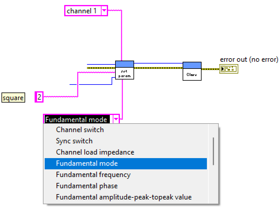
Set Instrument Frequency

API function: uci_WriteSimple()

image

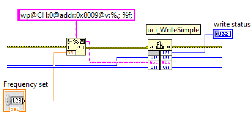
image: change the instrument frequency

The left half is a string formatter. It takes the frequency that you set on the control panel, and creates the correct string for the uci api.
If you enter 3000.5 Hz, the string will be wp@CH:0@addr:0x8009@v:3000.5;.
This string is passed to the Call Library Function block on the right side, that's configured for dll function uci_WriteSimple(). This block also gets the _session and _timeout values from the previous upstream flow.
The status is shown. _session and _timeout are passed along downstream.

In the next part, I review the Read and Close functionality. I'll also try to film the flow in action, together with the instrument.

Related blog:

MULTICOMP PRO MP750065 Function Generator - 1st impressions
Programming Pt1: SDK Demo
Programming Pt2: LabVIEW tryout (a)
Programming Pt3: LabVIEW tryout (b)
Programming Pt4: LabVIEW Driver Lib Init block
Programming Pt5: LabVIEW Driver Lib Read, Write and Close blocks
Programming Pt6: LabVIEW Driver Lib: High Level Functional blocks
  • Sign in to reply
  • Cancel

Top Replies

  • Jan Cumps
    Jan Cumps over 3 years ago in reply to Jan Cumps +1
    The driver is finished. This looks like the right balance between easy access to common functionality, and low level options for advanced use. Everything related to fundamental setup is implemented…
Parents
  • Jan Cumps
    Jan Cumps over 3 years ago

    Preview of the device driver. Here is the same flow as shown in the header of this post.
    Using my driver's Virtual Instrument blocks instead of the DLL calls:

    image

    It's not a 1-on-1 replacement. The driver has integrated error handling for the API calls, and retry if the initial DLL load fails.

    • Init block does the connection,
    • Then a write to change the frequency.
    • Read to get the current set frequency
    • Utility block to convert 8 bytes into a doubke, with endianness handling
    • Close block

    The Read and Write blocks will later become second class citizens.
    Main setting functions and reading parameters will have their own functional blocks, with the channel and (in case of setting values) input values as parameters.
    This will take care that you don't have to read the developer manual to set frequency, waveform, or query the instrument.

    • Cancel
    • Vote Up 0 Vote Down
    • Sign in to reply
    • Cancel
  • Jan Cumps
    Jan Cumps over 3 years ago in reply to Jan Cumps

    This is the next level of abstraction: a functional block that calls a particular function.
    Here it is set to change the waveform to square:
    image

    channel and parameter are selectable. For those parameters that aren't in my list, you can enter one manually. 

    I was first thinking to make separate functional blocks, but think that one block to set parameters, and one to get parameters, will do.
    To avoid that you have to study the programmer's guide, I added input value expectations to the parameter (= function) select box:
    image
    A compromise, but a fair one I think.

    This is what a series of commands looks like:
    image
    wave form is set to square, then front panel channel is switched on.

    • Cancel
    • Vote Up 0 Vote Down
    • Sign in to reply
    • Cancel
Reply
  • Jan Cumps
    Jan Cumps over 3 years ago in reply to Jan Cumps

    This is the next level of abstraction: a functional block that calls a particular function.
    Here it is set to change the waveform to square:
    image

    channel and parameter are selectable. For those parameters that aren't in my list, you can enter one manually. 

    I was first thinking to make separate functional blocks, but think that one block to set parameters, and one to get parameters, will do.
    To avoid that you have to study the programmer's guide, I added input value expectations to the parameter (= function) select box:
    image
    A compromise, but a fair one I think.

    This is what a series of commands looks like:
    image
    wave form is set to square, then front panel channel is switched on.

    • Cancel
    • Vote Up 0 Vote Down
    • Sign in to reply
    • Cancel
Children
  • Jan Cumps
    Jan Cumps over 3 years ago in reply to Jan Cumps

    The driver is finished. This looks like the right balance between easy access to common functionality, and low level options for advanced use.

    image

    Everything related to fundamental setup is implemented. 
    Not implemented as a functional block, but can be built from the other blocks: sweep, modulation, arbitrary waveforms.

    • Cancel
    • Vote Up +1 Vote Down
    • Sign in to reply
    • Cancel
element14 Community

element14 is the first online community specifically for engineers. Connect with your peers and get expert answers to your questions.

  • Members
  • Learn
  • Technologies
  • Challenges & Projects
  • Products
  • Store
  • About Us
  • Feedback & Support
  • FAQs
  • Terms of Use
  • Privacy Policy
  • Legal and Copyright Notices
  • Sitemap
  • Cookies

An Avnet Company © 2025 Premier Farnell Limited. All Rights Reserved.

Premier Farnell Ltd, registered in England and Wales (no 00876412), registered office: Farnell House, Forge Lane, Leeds LS12 2NE.

ICP 备案号 10220084.

Follow element14

  • X
  • Facebook
  • linkedin
  • YouTube