element14 Community
element14 Community
    Register Log In
  • Site
  • Search
  • Log In Register
  • About Us
  • Community Hub
    Community Hub
    • What's New on element14
    • Feedback and Support
    • Benefits of Membership
    • Personal Blogs
    • Members Area
    • Achievement Levels
  • Learn
    Learn
    • Ask an Expert
    • eBooks
    • element14 presents
    • Learning Center
    • Tech Spotlight
    • STEM Academy
    • Webinars, Training and Events
    • Learning Groups
  • Technologies
    Technologies
    • 3D Printing
    • FPGA
    • Industrial Automation
    • Internet of Things
    • Power & Energy
    • Sensors
    • Technology Groups
  • Challenges & Projects
    Challenges & Projects
    • Design Challenges
    • element14 presents Projects
    • Project14
    • Arduino Projects
    • Raspberry Pi Projects
    • Project Groups
  • Products
    Products
    • Arduino
    • Avnet Boards Community
    • Dev Tools
    • Manufacturers
    • Multicomp Pro
    • Product Groups
    • Raspberry Pi
    • RoadTests & Reviews
  • Store
    Store
    • Visit Your Store
    • Choose another store...
      • Europe
      •  Austria (German)
      •  Belgium (Dutch, French)
      •  Bulgaria (Bulgarian)
      •  Czech Republic (Czech)
      •  Denmark (Danish)
      •  Estonia (Estonian)
      •  Finland (Finnish)
      •  France (French)
      •  Germany (German)
      •  Hungary (Hungarian)
      •  Ireland
      •  Israel
      •  Italy (Italian)
      •  Latvia (Latvian)
      •  
      •  Lithuania (Lithuanian)
      •  Netherlands (Dutch)
      •  Norway (Norwegian)
      •  Poland (Polish)
      •  Portugal (Portuguese)
      •  Romania (Romanian)
      •  Russia (Russian)
      •  Slovakia (Slovak)
      •  Slovenia (Slovenian)
      •  Spain (Spanish)
      •  Sweden (Swedish)
      •  Switzerland(German, French)
      •  Turkey (Turkish)
      •  United Kingdom
      • Asia Pacific
      •  Australia
      •  China
      •  Hong Kong
      •  India
      •  Korea (Korean)
      •  Malaysia
      •  New Zealand
      •  Philippines
      •  Singapore
      •  Taiwan
      •  Thailand (Thai)
      • Americas
      •  Brazil (Portuguese)
      •  Canada
      •  Mexico (Spanish)
      •  United States
      Can't find the country/region you're looking for? Visit our export site or find a local distributor.
  • Translate
  • Profile
  • Settings
Test & Tools
  • Technologies
  • More
Test & Tools
Documents Programmable Electronic Load - Analyse the Summing Node Zero Point
  • Blog
  • Forum
  • Documents
  • Files
  • Members
  • Mentions
  • Sub-Groups
  • Tags
  • More
  • Cancel
  • New
Join Test & Tools to participate - click to join for free!
Actions
  • Share
  • More
  • Cancel
Engagement
  • Author Author: Jan Cumps
  • Date Created: 1 Dec 2017 4:08 PM Date Created
  • Last Updated Last Updated: 15 May 2020 3:38 PM
  • Views 8708 views
  • Likes 8 likes
  • Comments 107 comments
Related
Recommended

Programmable Electronic Load - Analyse the Summing Node Zero Point

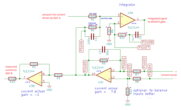
This blog documents investigates the feedback node of the electronic load that Robert Peter Oakes, jc2048 and Jan Cumps are designing.

It's an important spot in the load's design. It measures the set point and the feedback from the output.

When the output is driven to 0, it should be on a potential as close as possible to 0 V.

On the first prototype it's -0.2 V. Not so much off, but the negative value  influences our ADC measurements.

This document checks how we can get this node to 0 V.

image


Because this document is evolving, some comments below may be out of sync with the content. That's because the content is adapted based on the conversation.

The measurements taken here are based on the original design, without R32 in place and U3B + tied to ground.

The current sense side of R7 is connected to ground, and a variable negative voltage from 0 V down is applied to the current sense side of R8 to simulate current being sensed.


The circuit isn't complex. The set point is driven by a DAC. It's set to 0 for this test.

The second input to this node is OpAmp 3C. It has both inputs tied to ground so should theoretically have 0 V at the output.

On my board I measure a potential of -0.212V at the left side of R33.

I hope to get this closer to 0 V to ease the ADC a bit - its performance degrades with negative voltage at its inputs.

Like the other blogs for the electronic load, this is a working document that will be updated with findings from anyone who wants to chime in.


Behaviour at 0V


buzy image

  • metrology
  • differentiator
  • boosterpack
  • opamp
  • msp432
  • launchpad
  • analog
  • laboratory
  • instrument
  • Share
  • History
  • More
  • Cancel
  • Sign in to reply

Top Comments

  • jc2048
    jc2048 over 7 years ago in reply to Robert Peter Oakes +4
    As you say, changing the op-amp is one possibility. There are bipolar op-amps with much lower bias currents, but an alternative nowadays is a precision CMOS op-amp (you'd have to check whether other characteristics…
  • Robert Peter Oakes
    Robert Peter Oakes over 7 years ago +3
    To hopefully simplify things a little We have this, Upper op amp is simply to provide an inversion of the measured value back tot he ADC, hence the gain of -1 Lower right op amp measures the volts across…
  • jc2048
    jc2048 over 7 years ago in reply to Jan Cumps +3
    Love the advertisement for "John's excellent probes". It's like one those things from the old days of American TV where the presenter would suddenly turn, look very earnestly at the camera, and start reading…
Parents
  • jc2048
    jc2048 over 7 years ago

    This is unfair on Peter. It's his design yet you're having all the fun of sorting out the prototype.


    But if you're intent on doing this anyway...


    "On my board I measure a potential of -0.212V at the left side of R33"

    You need to measure the output of U3B too - it might be lower. The ADC will have some form of ESD protection and that might clamp the voltage. Only way to know is to measure both ends of R33 and see if they are different.


    Then you need to measure the output of U3C. You have two amplifiers in series and you need to know how much of a contribution each is making to whatever offset you measure at the output of U3B. That will give you some useful clues as to what is going on.


    (As Peter points out the meter input resistance will affect the readings, so start with measuring the outputs of the amplifiers because they are the lowest impedance points in the circuit and your meter has the least effect on them - the output impedance will be under a hundred ohms.)

    • Cancel
    • Vote Up +1 Vote Down
    • Sign in to reply
    • More
    • Cancel
  • Jan Cumps
    Jan Cumps over 7 years ago in reply to jc2048

    jc2048  wrote:


    "On my board I measure a potential of -0.212V at the left side of R33"

    You need to measure the output of U3B too - it might be lower. The ADC will have some form of ESD protection and that might clamp the voltage. Only way to know is to measure both ends of R33 and see if they are different.


    Then you need to measure the output of U3C. You have two amplifiers in series and you need to know how much of a contribution each is making to whatever offset you measure at the output of U3B. That will give you some useful clues as to what is going on.


    image

    • Cancel
    • Vote Up +1 Vote Down
    • Sign in to reply
    • More
    • Cancel
Comment
  • Jan Cumps
    Jan Cumps over 7 years ago in reply to jc2048

    jc2048  wrote:


    "On my board I measure a potential of -0.212V at the left side of R33"

    You need to measure the output of U3B too - it might be lower. The ADC will have some form of ESD protection and that might clamp the voltage. Only way to know is to measure both ends of R33 and see if they are different.


    Then you need to measure the output of U3C. You have two amplifiers in series and you need to know how much of a contribution each is making to whatever offset you measure at the output of U3B. That will give you some useful clues as to what is going on.


    image

    • Cancel
    • Vote Up +1 Vote Down
    • Sign in to reply
    • More
    • Cancel
Children
  • jc2048
    jc2048 over 7 years ago in reply to Jan Cumps

    Love the advertisement for "John's excellent probes". It's like one those things from the old days of American TV where the presenter would suddenly turn, look very earnestly at the camera, and start reading out the advert. Perhaps we could see if John would like to sponsor this episode of Circuit Conundrums (starring Jan Cumps as The Man with the Meter).


    The interesting figure is the 0.104V at the summing node. If there was only R2 and R4 in circuit, that voltage could only be 0.054V (give or take a little for the resistor tolerance). The fact that it's so high suggests that there's an additional contribution to the current through R2 from what's connected beyond the dotted line.


    The second clue is U3B. The op-amp is doing a good job of keeping the virtual earth at pin 6 close to GND, yet it has to position the output at -0.212V to do it (and not the -0.108V you would expect given the 0.108V at the output of U3C).


    What do they both suggest?

    • Cancel
    • Vote Up +3 Vote Down
    • Sign in to reply
    • More
    • Cancel
  • jc2048
    jc2048 over 7 years ago in reply to Jan Cumps

    In case anyone's interested in why the readings look to be out, here's a quick analysis of the situation.


    Jan has measured the voltages and we know the resistance values, so we can calculate the currents in each resistor for the two pairs. Like this...


    image


    The additional current into the node where the resistors join is then the difference between the two. The only place that current can come from is the op-amp, so Jan is doing an experiment to measure the input bias current of the input pins of the actual op-amp that he has on the board - the bias current for this particular op-amp flows out of the pin (shown with a negative sign on the datasheet).


    Here's what the datasheet says


    image


    so he's not  too far out, their typical figure is 0.8uA and he is measuring around 1uA. Well inside their maximum value (at 25C) of 2uA. (I've ignored any meter loading in all this.)

    • Cancel
    • Vote Up +1 Vote Down
    • Sign in to reply
    • More
    • Cancel
  • Robert Peter Oakes
    Robert Peter Oakes over 7 years ago in reply to jc2048

    So a couple of possibilities

    Change the op-amp or reduce the 100K s to reduce the effect of the op-amp node, this would increase the risk of a fault condition blowing the op-amp but would fix the error, relatively of course, by going to say a pair of 20K we would improve things by 5*


    Thoughts?

    • Cancel
    • Vote Up +3 Vote Down
    • Sign in to reply
    • More
    • Cancel
  • jc2048
    jc2048 over 7 years ago in reply to Robert Peter Oakes

    As you say, changing the op-amp is one possibility. There are bipolar op-amps with much lower bias currents, but an alternative nowadays is a precision CMOS op-amp (you'd have to check whether other characteristics were good enough).


    Lowering the resistor values would be good anyway, but there's a limit to how far you can go and it still leaves quite an error. The measured value is way out and though you could try and compensate in software it's messy because it will vary from unit to unit.


    A third option, that a textbook would give you, is to balance the input resistances. It's something that Jan could try quickly with what he's already built, if he wanted to.


    For the inverting amplifer U3B, lift the non-inverting pin and connect a 50k resistor from the pin to ground. (If you don't have a 50k 1% resistor, use two of the 100k ones in parallel.)  That gets you this


    image


    the output of U3B should now be much closer to the gain of -1 and with 0.108V going in should read within a millivolt or two of -0.108V. At least that's what theory says. Try it and see.


    To understand why it works, look at the line above the one I highlighted on the datsheet (offset current). That's saying that, although the bias current is fairly high, the difference in the bias current of the two inputs is quite small (no more than one part in a hundred - less than 1%). That comes about because, although the bias current is the base drive to a transistor and is a bit variable  (it will vary from batch to batch), the transistors on a particular chip match very well in their characteristics (because they're all fabbed together). That matching can be made use of.


    For this part, the bias current is out of the input pin (it's the base current of a PNP transistor). When it flows through whatever resistance is connected to the pin it generates a voltage. If the resistance seen by both inputs is the same, then those voltages will be the same (we don't know precisely what the voltage will be, because the bias current varies quite a lot, but we do know that both inputs will see a very similar additional voltage because the currents match well). Since the two inputs are difference inputs, the two voltages will then pretty much cancel out as part of the normal action of the op-amp.


    After Jan had done that (and assuming that it worked), he could then move on to the differential amplifier (U3C). To achieve the same effect there he merely needs to install the 680k to ground. Then we can see how close it brings things overall to the kind of accuracy you want. I suspect you'll want to move to a more up-to-date precision part (particularly if Jan is hoping to get anything close to the accuracy implied by working 16 bits), but let's see (and it's an interesting experiment to do, anyway).

    • Cancel
    • Vote Up +4 Vote Down
    • Sign in to reply
    • More
    • Cancel
  • Jan Cumps
    Jan Cumps over 7 years ago in reply to jc2048

    I'll try the 3rd option next weekend. I don't specifically need the precision but it's an interesting exercise. I think I'll pass on using a higher precision opamp for now. Time to move on to the high piwer part, then get operational firmware.

    • Cancel
    • Vote Up +1 Vote Down
    • Sign in to reply
    • More
    • Cancel
  • Jan Cumps
    Jan Cumps over 7 years ago in reply to jc2048

    jc2048  wrote:

    ...


    A third option, that a textbook would give you, is to balance the input resistances. It's something that Jan could try quickly with what he's already built, if he wanted to.


    For the inverting amplifer U3B, lift the non-inverting pin and connect a 50k resistor from the pin to ground. (If you don't have a 50k 1% resistor, use two of the 100k ones in parallel.)  That gets you this


    image


    the output of U3B should now be much closer to the gain of -1 and with 0.108V going in should read within a millivolt or two of -0.108V. At least that's what theory says. Try it and see.


    To understand why it works, look at the line above the one I highlighted on the datsheet (offset current). That's saying that, although the bias current is fairly high, the difference in the bias current of the two inputs is quite small (no more than one part in a hundred - less than 1%). That comes about because, although the bias current is the base drive to a transistor and is a bit variable  (it will vary from batch to batch), the transistors on a particular chip match very well in their characteristics (because they're all fabbed together). That matching can be made use of.


    For this part, the bias current is out of the input pin (it's the base current of a PNP transistor). When it flows through whatever resistance is connected to the pin it generates a voltage. If the resistance seen by both inputs is the same, then those voltages will be the same (we don't know precisely what the voltage will be, because the bias current varies quite a lot, but we do know that both inputs will see a very similar additional voltage because the currents match well). Since the two inputs are difference inputs, the two voltages will then pretty much cancel out as part of the normal action of the op-amp.


    ...

    I have added the 50K from non-inverting input to ground of U3B.

    The voltage at that input is 0.051 V.

    On the output, it's - 0.106 V.

    • Cancel
    • Vote Up +1 Vote Down
    • Sign in to reply
    • More
    • Cancel
  • Jan Cumps
    Jan Cumps over 7 years ago in reply to jc2048

    jc2048  wrote:


    ...


    After Jan had done that (and assuming that it worked), he could then move on to the differential amplifier (U3C). To achieve the same effect there he merely needs to install the 680k to ground. Then we can see how close it brings things overall to the kind of accuracy you want. I suspect you'll want to move to a more up-to-date precision part (particularly if Jan is hoping to get anything close to the accuracy implied by working 16 bits), but let's see (and it's an interesting experiment to do, anyway).

    With R32, 680K in place, the voltage at the entry of ADC1 is -0.005V as measured by my DMM,

    The ADC measures -0.00581250 V (65506)

    • Cancel
    • Vote Up +2 Vote Down
    • Sign in to reply
    • More
    • Cancel
  • jc2048
    jc2048 over 7 years ago in reply to Jan Cumps

    Does it still affect the other ADC channels (going negative by only 5mV) or is it going to be usable in normal operating conditions?


    You've still got the problem with abnormal conditions - ie if someone connects the load output the wrong way round. Perhaps the way to deal with that would be to make it a 'perfect diode' circuit, though that wouldn't give you any warning that the output was connected wrongly.


    5mV error is a bit better than 200mV, so it's a definite improvement (worth having for two extra resistors). But it's only 40 times better and substituting an op-amp with bias currents maybe a thousand times less would give much more benefit.


    If you take a look at the datasheet above, you'll see that the voltage offset error is typ 0.5mV and may be more. Amplified by the 6.8 gain of the differential amplifier, that gives the potential for several millivolts of error at the ADC input. Saying it another way, the reduced bias current error is now around the same level as the voltage offset errors, which means, if you want to go further and try and make it even more precise, you're trying to work with (and disentangle) two error sources rather than just the one.

    • Cancel
    • Vote Up +1 Vote Down
    • Sign in to reply
    • More
    • Cancel
  • Jan Cumps
    Jan Cumps over 7 years ago in reply to jc2048

    jc2048  wrote:


    Does it still affect the other ADC channels (going negative by only 5mV) or is it going to be usable in normal operating conditions?


    ...

    The ADC seems to behave well up to at least -250 mV, and has errors on all channels when one input is below -700 mV. I haven't checked the in-between yet to find the tipping point - and haven't investigated the datasheet for this condition.


    jc2048  wrote:


    ...


    You've still got the problem with abnormal conditions - ie if someone connects the load output the wrong way round. Perhaps the way to deal with that would be to make it a 'perfect diode' circuit, though that wouldn't give you any warning that the output was connected wrongly.


    ...

    Yes, I will have to test what situations can cause negative values on ADCs in normal conditions too.


    jc2048  wrote:


    ...


    5mV error is a bit better than 200mV, so it's a definite improvement (worth having for two extra resistors). But it's only 40 times better and substituting an op-amp with bias currents maybe a thousand times less would give much more benefit.


    If you take a look at the datasheet above, you'll see that the voltage offset error is typ 0.5mV and may be more. Amplified by the 6.8 gain of the differential amplifier, that gives the potential for several millivolts of error at the ADC input. Saying it another way, the reduced bias current error is now around the same level as the voltage offset errors, which means, if you want to go further and try and make it even more precise, you're trying to work with (and disentangle) two error sources rather than just the one.

    An exercise for the future or for someone who wants to improve the design - and certainly an interesting one.

    • Cancel
    • Vote Up +1 Vote Down
    • Sign in to reply
    • More
    • Cancel
  • Robert Peter Oakes
    Robert Peter Oakes over 7 years ago in reply to Jan Cumps

    The bad connections is or should be a one time issue during build, it should not occur after that


    The issue comes up once the built in protection diodes start to conduct, aka about 250mV ish

    • Cancel
    • Vote Up +1 Vote Down
    • Sign in to reply
    • More
    • Cancel
element14 Community

element14 is the first online community specifically for engineers. Connect with your peers and get expert answers to your questions.

  • Members
  • Learn
  • Technologies
  • Challenges & Projects
  • Products
  • Store
  • About Us
  • Feedback & Support
  • FAQs
  • Terms of Use
  • Privacy Policy
  • Legal and Copyright Notices
  • Sitemap
  • Cookies

An Avnet Company © 2025 Premier Farnell Limited. All Rights Reserved.

Premier Farnell Ltd, registered in England and Wales (no 00876412), registered office: Farnell House, Forge Lane, Leeds LS12 2NE.

ICP 备案号 10220084.

Follow element14

  • X
  • Facebook
  • linkedin
  • YouTube