

This blog documents focuses on the temperature protection of the electronic load that Robert Peter Oakes, jc2048 and Jan Cumps are designing.
|
The first exercise is to find the right Temperature vs Resistance table for the NTC I'm using.
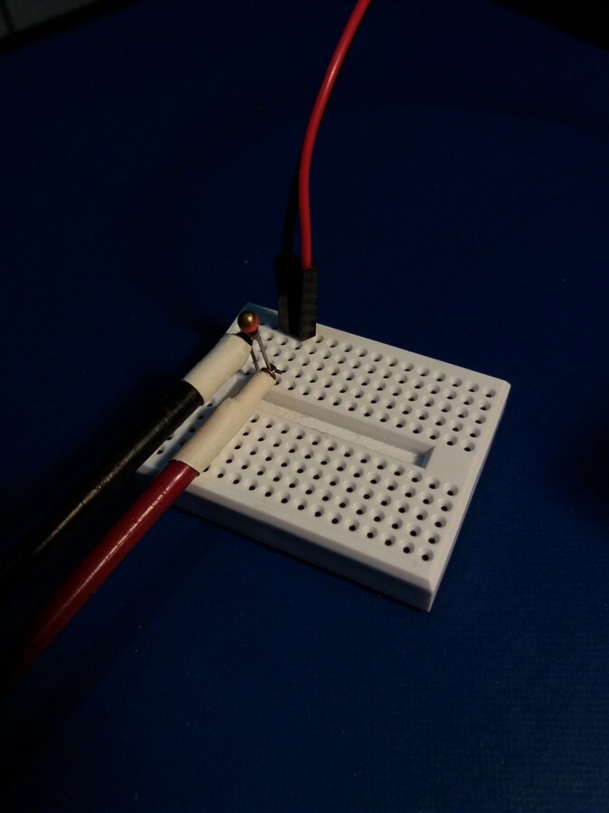
In this article I use a Vishay NTCLE100E3103J. That's a different component than the one in the final design.
There are two reasons:
- I have this one available for testing and it's through-hole. That makes prototyping easier
- Our final design doesn't prescribe the NTC to be used. The characteristics can be programmed and saved in FLASH (if all works out).
It's good to have two different components to validate that this flexibility works.
Temperature Sensor and How To Get Resistance vs Temperature
The component we're using for testing is a Vishay NTCLE100E3103NTCLE100E3103. If you want to follow along, click on the product link to get the datasheet.
It's a 10K thermistor with a negative temperature coefficient, 5% tolerance, Beta 3977 K.
The datasheet specifies the calculations that can be used to calculate resistance for a certain temperature. I can use them in the firmware - they apply for many NTCs of the same make.
In that case, the configuration would require a few parameters and temperature can be derived from that.
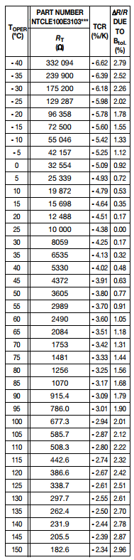
In this design I'm implementing something simpler, based on lookup values. Most datasheets contain a table that lays out resistance vs temperature.
Here is the one for the device I'm using in this blog (again: different than the final design (from the datasheet linked above, page 10).
We're not building a thermometer. We're not interested in how warm the FET exactly is (ok, maybe you are. In that case you can use a SCPI command to get the voltage at the NTC and derive the exact temperature  ).
).
What we want to know is if we're operating in the FET's comfort zone, if it's still safe to touch, if we're running hot, near critical and over-temperature.
Check here for the calculations used: https://en.wikipedia.org/wiki/Voltage_divider
Somewhat random, I've defined these as following:
| Status | Temperature (C) |
|---|---|
| normal | < 45° |
| warm | < 75° |
| hot | >= 75° |
| warning | >= 100° |
| over temperature | >= 125° |
The firmware will not know the exact temperature. It only defines these 5 buckets. It's up to the user to define the resistance at the tipping points.
Also, because these levels are chosen based on no science or regulations - and because I want to keep the temperature of the FET and thermistor I'm using under 125°, these may not apply to you.
Feel free to propose different temperatures or a different approach.
Firmware
The NTC thermistor TH1 is connected to ADC C. Once the voltage measured on the NTC drops below a certain point (because the max temperature is reached), the over-temperature protection should kick in.
That tipping voltage is stored in our calibration data. Check Programmable Electronic Load - Calibration Steps for the instructions to set that point.
typedef struct CalibrationData {
    uint32_t version;
    float temperature_threshold;  // todo convert to the ADC 16 bit value in stead of float
} CalibrationData;
As a convenience for the person that performs the configuration, the firmware calculates that voltage based on the resistance of the NTC at the over-temperature point.
So you don't have to enter a voltage during calibration. Instead, you look up the resistance of the NTC at switch-off point in the NTC's data sheet (say 125°C) and enter that value, in Ohm.
The firmware will use the voltage divider formulas to derive the voltage at that tipping point (and also back to resistance in the case the user queries the set point).
The calibration API has two functions to get and set that resistance at tipping point, and some helpers.
/**
 * this function expects the resistance of the NTC thermistor at the point where the electronic load is overheated.
 * It then calculates, based on the fact that the voltage is 5V and that the NTC is the lower part of a voltage divider
 * where the other resistor is 10K, the voltage that appears on ADC C if the maximum temperature is reached
 */
bool calibrationSetTemperatureMaxResistance(uint32_t value) {
    if(_bCalibrationActive) {
        // formula: Vout = Vin*Rt/(R1+Rt)
        // https://en.wikipedia.org/wiki/Voltage_divider
        _CalibrationData.temperature_threshold = ((5.0*value)/(10000.0+value)); // todo convert to the ADC 16 bit value in stead of float
    }
    return _bCalibrationActive;
}

/**
 * this function returns the resistance of the NTC thyristor at the point where the electronic load is overheated.
 *
 */
uint32_t calibrationGetTemperatureMaxResistance() {
    uint32_t uRetVal = 0U;
    // formula: Rt = R1.(1/((Vin/Vout)-1))
    // https://en.wikipedia.org/wiki/Voltage_divider
    uRetVal = 10000.0 * (1.0/((5.0/_CalibrationData.temperature_threshold)-1.0)); // todo convert to the ADC 16 bit value in stead of float
    return uRetVal;
}

float calibrationGetTemperatureMaxFloat() { // todo: remove when we turned all overload functionality to uint
    return _CalibrationData.temperature_threshold;
}
The over-temperature watchdog is an RTOS task. It runs every second and checks if the value sampled by ADC C drops below the value in the calibration data.
If that's the case, it disables the input of the electronic load.
*
 *  ======== fnTaskTemperatureOverProtection ========
 *  Task for this function is created statically. See the project's .cfg file.
 */
Void fnTaskTemperatureOverProtection(UArg arg0, UArg arg1)
{
    float fSample;
    while (1)
    {
        if (calibrationGetTemperatureMaxResistance()) { // if enabled
            fSample = eLoadDevelopGetAdcVolt(2);
            if (fSample > 0.0) { // ignore if no samples been taken yet
                if ( fSample < calibrationGetTemperatureMaxFloat()) { // todo this should be a uint calculation
                    eloadInputEnable(false);
                }
            }
        }
        Task_sleep(arg0);
    }
}
Timings
A warning about the time between the FET heating up and the protection kicking in. There are a series of delays:
- it takes a little time for the thermistor to get to the same temperature as the FET.
- the ADC is sampled every second then cached, so the data may be 1 second old
- the temperature overload watchdog runs every second. So worst case it takes 2 seconds before the firmware detects the over temperature.
- switching off the output is done via an RTOS message and i²c communication to an I/O chip. This also takes (at the moment unknown because not measured) time.
Change Over-temperature Protection, Temporary or Permanent
The instrument has SCPI functions to query and change the protection setting. Check here for the documentation: Programmable Electronic Load - Calibration Steps
To query the current setting, execute the following SCPI command:
CALibration:TEMPERATUREMAXResistance?
You'll get the value that's currently active.
To change or disable the over-temperature protection, there's another SCPI command.
Because this is a command that alters calibration settings, you first have to activate a calibration session.
CALibration:STArt
CALibration:TEMPERATUREMAXResistance 0
The value 0 will deactivate over-protection. Any other value will make the watchdog trip as soon as the thermistor drops below the entered resistance.
With the example of the NTC data sheet table above, to make the device switch off at 125° C, you'd enter:
CALibration:TEMPERATUREMAXResistance 339
For the NTC that's suggested in this build, the command to switch off at 125° C is:
CALibration:TEMPERATUREMAXResistance 518
The settings are active immediately, but not stored in the permanent calibration memory.
If you power-cycle the instrument or reset it, the original calibration point is restored. (note: the *RST SCPI command does not restore calibration data)
If you want to make your changes permanent, run the following SCPI command to close the calibration session and write the value to Flash:
CALibration:END
As long as you haven't executed the CALibration:END command, every change is temporary and you can revert back to the previous calibration state.
Once you've executed it, the current calibration state will be the new active state, also after power-cycle or reset.
Initial Setting when you Program the Firmware the 1st Time
Initially, over-temperature protection is undefined. The calibration value is stored in Flash and the Code Composer Studio project is configured to not touch this memory area.
Depending on what you've done before with the MSP432, this area may be filled with 0xFFFFFFFF values or something else (e.g. if you've ever ran the MSP432 DriverLib Flash Controller example, the area may contain 0xA5A5A5A5).
It's part of the initial setup to define the proper setting for over-temperature when initialising and configuring the instrument before first use.
Top Comments
-

Jan Cumps
-
Cancel
-
Vote Up
0
Vote Down
-
-
Sign in to reply
-
More
-
Cancel
-

shabaz
in reply to Jan Cumps
-
Cancel
-
Vote Up
+2
Vote Down
-
-
Sign in to reply
-
More
-
Cancel
Comment-

shabaz
in reply to Jan Cumps
-
Cancel
-
Vote Up
+2
Vote Down
-
-
Sign in to reply
-
More
-
Cancel
Children