

This blog documents explains how to calibrate the electronic load that Robert Peter Oakes, jc2048 and Jan Cumps are designing.
Some functionality of the instrument are dependent on the components you select and tolerances. Follow the steps below to initialise the instrument after the build and to correct for drift and these tolerances. |
Status: calibration functions available for
- temperature protection,
- sense resistor,
- current set,
- current read,
- voltage read
Approach
Calibration and configuration are done via SCPI commands.
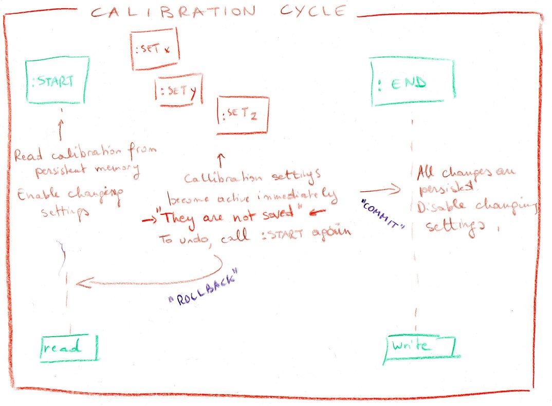
You init the calibration session, perform steps and close the session.
While a calibration session is active, any changes made to the calibration settings are active but not saved.
At session closure, calibration data is stored on the device.
Inspiration for the sequence of activities comes from the RIGOL DP800 SCPI calibration user's guide.
Calibration Sequence
Opening sequence
CALibration:STArt
Inform the device that a calibration/configuration session starts.
If you don't do this, any other calibration "set" command will throw an error and no changes will be applied to the instrument's calibration data.
The Clear and *RST commands aren't implemented. I'm not sure yet if the Clear command is desired or needed. There's no discussion on the *RST command, we'll have to implement that at some time to put the device in a known state. |
CALibration:STArt ...
CALibration:Clear ... // NOT implemented
*RST
Calibration sequence
When a session is opened, you can start using calibration "set" commands. "Query" commands also work without a session opened.
If used without a session, they will return the stored values. If used in a session, they reflect whatever changes are done during the session
CALibration:SET ...
CALibration:MEAs ...
Closing sequence
CALibration:END
The End comment saves the settings to the device. As long as you don't call this command, no changes are permanent. They will only stay active as long as the device isn't reset or power cycled.
If you want to undo any changes and start over again, call the Start function again.
If you want to cancel the exercise, power cycle the device.
CALibration:END ....
Error: throws SCPI_ERROR_EXECUTION_ERROR if there is no active calibration session
Configure the Over Temparature Protection
Two API functions are available to set the over-temperature protection:
CALibration:TEMPERATUREMaxResistance
CALibration:TEMPERATUREMaxResistance?
The value related to this function is the resistance of thermistor TH1 at the temperature where protection should kick in.
If the value is 0, temperature overprotection is disabled. This is the default behaviour of the device if the designer doesn't go through the calibration procedure  .
.
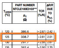
That value (in Ohm) is typically documented in the datasheet for the thermistor you're using in your design. Check this post for more info: Programmable Electronic Load - Temperature Protection.
In this example, we want to switch off the input when the temperature reaches 125°C. The data sheet of our NTC documents 339 Ohm for that temperature.
Get the Tripover Temperature setting:
CALibration:TEMPERATUREMAXResistance?
This function will return the resistance of the NTC when the protection will kick in, in Ohm
A return value of 0 indicates that temperature protection is inactive.
Example:
CALibration:TEMPERATUREMAXResistance?
339
Set the Tripover temperature setting:
CALibration:TEMPERATUREMAXResistance [NUMBER]
This function will set the resistance of the NTC when the protection should kick in.
Example:
CALibration:STArt
*RST
CALibration:TEMPERATUREMAXResistance 339
CALibration:END
When using the default NTC https://www.element14.com/community/view-product.jspa?fsku=2103179&nsku=NULL&COM=noscriptVishay NTCS0805E3103JLTVishay NTCS0805E3103JLT (see Programmable Electronic Load - Power Stage) this command will enable over-temperature protection at 125°C:
CALibration:TEMPERATUREMAXResistance 518
Error: throws SCPI_ERROR_EXECUTION_ERROR if there is no active calibration session
Configure the Current Sense Resistor
Two API functions are available to set the sense resistor value:
CALibration:SENSEResistance
CALibration:SENSEResisitance?
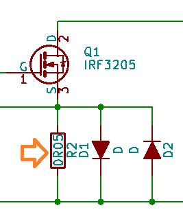
The value related to this function is the resistance of the sense resistor R2 on the MOSFET board.
Get the Sense Resistor setting:
CALibration:SENSEResistance?
This function will return the resistance of the current sense resistor as stored in calibration data.
Example:
CALibration:SENSEResistance?
0.05
Set the Sense Resistor setting:
CALibration:SENSEResistance [NUMBER]
This function will set the resistance of the current sense resistor in the calibration data.
Example:
CALibration:STArt
*RST
CALibration:SENSEResistance 0.05
CALibration:END
Error: throws SCPI_ERROR_EXECUTION_ERROR if there is no active calibration session
Error: throws SCPI_ERROR_ILLEGAL_PARAMETER_VALUE if you set the value to 0.
Configure the Input Voltage Sense Read Correction
Five API functions are available to correct the Input Volage Sense measurement:
CALibration:SENSEVOLTREADOffset
CALibration:SENSEVOLTREADOffset?
CALibration:SENSEVOLTREADMultiplier
CALibration:SENSEVOLTREADMultiplier?
CALibration:ADC2:VOLT?
The offset is the DC component measured by the ADC when the sense inputs of the instrument are shortcut.
The multiplier is the gain in the circuit between the sense inputs and the ADC.
The input voltage sense signals are measured by opamp U3D.
This opamp has a gain of 0.033. It divides the voltage by 33.3333333.
That value is then sampled by ADC 2.
To show the correct voltage at the sense inputs, we have to multiply the sampled value again by theoretically 33.3333.
To correct for the tolerances of the input circuit, the instrument allows you to fine tune this offset and multiplier.
It requires a calculator and a reference voltage.
To correct the offset, shortcut the sense inputs of the load.
That should give us a value at the ADC of 0 V.
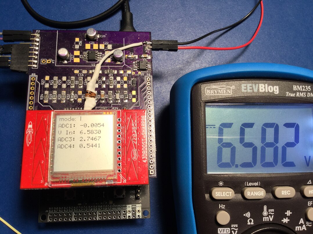
Then check the voltage of the ADC 2, using CALibration:ADC2:VOLT?. This returns -0.0057 V in my case.
We use CALibration:SENSEVOLTREADOffset to store this measurement in Flash. All future measurements will take the offset into account.
Start a calibration session with CALibration:STArt and configure the multiplier with CALibration:SENSEVOLTREADOffset -0.0057.
Check if the value is accepted with CALibration:SENSEVOLTREASOffset?.
When OK, close the session and save the settings by calling CALibration:END.
To correct the multiplier, provide a precise voltage at the voltage sense inputs. If you have a voltage reference (there is one on the ADC/DAC board), you can use that. Else use a power supply and a reasonable DMM.
I use a lab power supply and set it close to the maximum voltage that gives 3 digit precision on my DMM: 6.583. The DMM is connected on the same voltage sense inputs
Then check the voltage of the ADC 2, using CALibration:ADC2:VOLT?. This returns 0.218063 in my case.
The multiplier for my board is 6.583 / 0.218063 = 30.188523500089423698655893021741.
Start a calibration session with CALibration:STArt and configure the multiplier with CALibration:SENSEVOLTREADMultiplier 30.188523500089423698655893021741.
Check if the value is accepted with CALibration:SENSEVOLTREADMultiplier?.
When OK, close the session and save the settings by calling CALibration:END.
Get the ADC 2 sampled voltage:
CALibration:ADC2:VOLT?
This function will return the currents sampled voltage at ADC 2. This value should be close to the volt on the voltage sense inputs divided by 33.3333
Example:
CALibration:ADC2:VOLT?
0.218063
Get the voltage read offset setting:
CALibration:SENSEVOLTREADOffset?
This function will return the input voltage sense offset. This value should be close to 0.0.
The instrument uses 0.0 in the case that the calibration hasn't been set to return the voltage via SCPI and LCD display.
Example:
CALibration:SENSEVOLTREADOffset?
0.1225
Set the voltage read offset setting:
CALibration:SENSEVOLTREADOffset [FLOAT]
This function will set the input voltage sense offset.
Example:
CALibration:STArt
*RST
CALibration:SENSEVOLTREADOffset -0.0057
CALibration:END
Error: throws SCPI_ERROR_EXECUTION_ERROR if there is no active calibration session
Get the voltage read multiplier setting:
CALibration:SENSEVOLTREADMultiplier?
This function will return the input voltage sense multiplier. This value should be close to 33.3333.
A return value of 0 indicates that the multiplier is not set. The instrument uses 33.3333 in that case to return the voltage via SCPI and LCD display.
Example:
CALibration:SENSEVOLTREADMultiplier?
30.1885
Set the voltage read multiplier setting:
CALibration:SENSEVOLTREADMultiplier [FLOAT]
This function will set the input voltage sense read multiplier.
Example:
CALibration:STArt
*RST
CALibration:SENSEVOLTREADMultiplier 30.188523500089423698655893021741
CALibration:END
Error: throws SCPI_ERROR_EXECUTION_ERROR if there is no active calibration session
Configure the Input Current Read Correction
Five API functions are available to correct the Input Current measurement:
CALibration:CURRENTREADOffset
CALibration:CURRENTREADOffset?
CALibration:CURRENTREADMultiplier
CALibration:CURRENTREADMultiplier?
CALibration:ADC1:VOLT?
The offset is the DC component measured by the ADC when the load inputs of the instrument are shortcut.
The multiplier is the gain in the circuit between the load inputs and the ADC.
The input voltage sense signals are measured by opamp U3C and U3B.
This opamps have a gain of -6.8 and -1. They divide the voltage measured over the current sense resistor by 6.8.
That value is then sampled by ADC 1.
To show the correct current at the load inputs, we have to multiply the sampled value again by theoretically 6.8 (and apply Ohm's law to turn the voltage to a current, but that's not relevant in this exercise).
To correct for tolerances in the input circuit, the instrument allows you to fine tune this offset and multiplier.
It requires a calculator a power supply and two DMMs.
To correct the offset, shortcut the load inputs of the load.
That should give us a value at the ADC of 0 V.
Then check the voltage of the ADC 1, using CALibration:ADC1:VOLT?. This returns 0.00112500 V in my case.
We use CALibration:CURRENTREADOffset to store this measurement in Flash. All future measurements will take the offset into account.
Start a calibration session with CALibration:STArt and configure the multiplier with CALibration:CURRENTREADOffset 0.00112500.
Check if the value is accepted with CALibration:CURRENTREADOffset?.
When OK, close the session and save the settings by calling CALibration:END.
To correct the multiplier, provide a stable voltage at the load inputs. Add a good DC current meter in series.
Set DAC 1 to a value so that the current meter shows 1 A. // todo: provide a calibration function. Currently it is the very low level DEVE:DAC1 xxxxx.
Measure the voltage over the current sense resistor with a second multimeter. I measure 0.05 V.
Then check the voltage of the ADC 1, using CALibration:ADC1:VOLT?. This returns 0.0073529411764706 V in my case.
The multiplier for my board is 0.05 / 0.0073529411764706 = 6.8493.
Start a calibration session with CALibration:STArt and configure the multiplier with CALibration:CURRENTREADMultiplier 6.8493.
Check if the value is accepted with CALibration:CURRENTREADMultiplier?.
When OK, close the session and save the settings by calling CALibration:END.
Get the ADC 1 sampled voltage:
CALibration:ADC1:VOLT?
This function will return the currents sampled voltage at ADC 1. This value should be close to the volt on the current sense resistor divided by 6.8.
Example:
CALibration:ADC1:VOLT?
0.007363
Get the current read offset setting:
CALibration:CURRENTREADOffset?
This function will return the input current read offset. This value should be close to 0.0.
The instrument uses 0.0 in the case that the calibration hasn't been set to return the current via SCPI and LCD display.
Example:
CALibration:CURRENTREADOffset?
0.1885
Set the current reads offset setting:
CALibration:CURRENTREADOffset [FLOAT]
This function will set the input current offset.
Example:
CALibration:STArt
*RST
CALibration:CURRENTREADOffset 0.1885
CALibration:END
Error: throws SCPI_ERROR_EXECUTION_ERROR if there is no active calibration session
Get the current read multiplier setting:
CALibration:CURRENTREADMultiplier?
This function will return the input current multiplier. This value should be close to 6.8.
A return value of 0 indicates that the multiplier is not set. The instrument uses 6.8 in that case to return the current via SCPI and LCD display.
Example:
CALibration:CURRENREADTMultiplier?
6.8493
Set the current read multiplier setting:
CALibration:CURRENTREADMultiplier [FLOAT]
This function will set the input current read multiplier.
Example:
CALibration:STArt
*RST
CALibration:CURRENTREADMultiplier 6.8493
CALibration:END
Error: throws SCPI_ERROR_EXECUTION_ERROR if there is no active calibration session
Configure the Input Current Set Correction
Five API functions are available to correct the Input Current setting:
CALibration:CURRENTWRITEOffset
CALibration:CURRENTWRITEOffset?
CALibration:CURRENTWRITEMultiplier
CALibration:CURRENTWRITEMultiplier?
CALibration:ADC1:VOLT?
The offset is the DC component measured when the DAC is set to 0.
The multiplier is the translation of the DAC setting vs the FET output.
These settings allow to deal with different FETs. It also compensates OpAmp and DAC tolerances.
To correct for tolerances in the loadcircuit, the instrument allows you to fine tune this offset and multiplier.
It requires a calculator a power supply and a DMM (or an already calibrated current read on the load).
To correct the offset, load the input with a significan voltage (say: more than 10 V) the load inputs of the load.
That should give us a value at the ADC of 0 V, enable the input and set the DAC to 0.
... to be continued
Top Comments
-

Jan Cumps
-
Cancel
-
Vote Up
+2
Vote Down
-
-
Sign in to reply
-
More
-
Cancel
Comment-

Jan Cumps
-
Cancel
-
Vote Up
+2
Vote Down
-
-
Sign in to reply
-
More
-
Cancel
Children