element14 Community
element14 Community
    Register Log In
  • Site
  • Search
  • Log In Register
  • Community Hub
    Community Hub
    • What's New on element14
    • Feedback and Support
    • Benefits of Membership
    • Personal Blogs
    • Members Area
    • Achievement Levels
  • Learn
    Learn
    • Ask an Expert
    • eBooks
    • element14 presents
    • Learning Center
    • Tech Spotlight
    • STEM Academy
    • Webinars, Training and Events
    • Learning Groups
  • Technologies
    Technologies
    • 3D Printing
    • FPGA
    • Industrial Automation
    • Internet of Things
    • Power & Energy
    • Sensors
    • Technology Groups
  • Challenges & Projects
    Challenges & Projects
    • Design Challenges
    • element14 presents Projects
    • Project14
    • Arduino Projects
    • Raspberry Pi Projects
    • Project Groups
  • Products
    Products
    • Arduino
    • Avnet Boards Community
    • Dev Tools
    • Manufacturers
    • Multicomp Pro
    • Product Groups
    • Raspberry Pi
    • RoadTests & Reviews
  • Store
    Store
    • Visit Your Store
    • Choose another store...
      • Europe
      •  Austria (German)
      •  Belgium (Dutch, French)
      •  Bulgaria (Bulgarian)
      •  Czech Republic (Czech)
      •  Denmark (Danish)
      •  Estonia (Estonian)
      •  Finland (Finnish)
      •  France (French)
      •  Germany (German)
      •  Hungary (Hungarian)
      •  Ireland
      •  Israel
      •  Italy (Italian)
      •  Latvia (Latvian)
      •  
      •  Lithuania (Lithuanian)
      •  Netherlands (Dutch)
      •  Norway (Norwegian)
      •  Poland (Polish)
      •  Portugal (Portuguese)
      •  Romania (Romanian)
      •  Russia (Russian)
      •  Slovakia (Slovak)
      •  Slovenia (Slovenian)
      •  Spain (Spanish)
      •  Sweden (Swedish)
      •  Switzerland(German, French)
      •  Turkey (Turkish)
      •  United Kingdom
      • Asia Pacific
      •  Australia
      •  China
      •  Hong Kong
      •  India
      •  Korea (Korean)
      •  Malaysia
      •  New Zealand
      •  Philippines
      •  Singapore
      •  Taiwan
      •  Thailand (Thai)
      • Americas
      •  Brazil (Portuguese)
      •  Canada
      •  Mexico (Spanish)
      •  United States
      Can't find the country/region you're looking for? Visit our export site or find a local distributor.
  • Translate
  • Profile
  • Settings
Test & Tools
  • Technologies
  • More
Test & Tools
Documents Programmable Electronic Load - ADC Firmware
  • Blog
  • Forum
  • Documents
  • Files
  • Members
  • Mentions
  • Sub-Groups
  • Tags
  • More
  • Cancel
  • New
Join Test & Tools to participate - click to join for free!
Actions
  • Share
  • More
  • Cancel
Engagement
  • Author Author: Jan Cumps
  • Date Created: 3 May 2020 10:24 AM Date Created
  • Last Updated Last Updated: 6 Oct 2021 10:20 PM
  • Views 2115 views
  • Likes 5 likes
  • Comments 17 comments
Related
Recommended

Programmable Electronic Load - ADC Firmware

This post documents the ADC firmware for the electronic load we made here on element14.

image


ADC


image


ADC samples are taken all the time, based on a TI-RTOS schedule.

Data is written to a round-robin buffer with 2 buckets.


volatile ADCValues adcRoundRobin[2];
volatile uint32_t adcRoundRobinIndex[ADC_ACTIVE_INPUTS] = {0};


One bucket has stable data and can be read whenever needed. A read pointer points to that stable bucket.

The other bucket is used to write sample data. Once samples from 4 channels are collected, the read pointer is toggled so that it points to that fresh data.

I've optimised this. I've added a read pointer for each channel now:


volatile uint32_t adcRoundRobinIndex[ADC_ACTIVE_INPUTS] = {0};


Once a channel is collected, the read pointer for that channel is toggled so that it points to the fresh data.


void *threadADC(void *arg0) {
    uint32_t i;


    a_i2cTransaction.writeBuf = a_txBuffer;
    a_i2cTransaction.readBuf = a_rxBuffer;
    a_i2cTransaction.slaveAddress = ADC_I2C_ADDR;


    // this buffer value never changes. Let's set it at the start.
    // If for some reason this becomes a variable value,
    // move to sampleADC()
    a_txBuffer[2] = ADS1115_CFG_L;


    while (1)
    {
        for (i =0; i< ADC_ACTIVE_INPUTS; i++) {
            // we write value to the inactive robin
            // store value of ADC[i]
            // the ADC needs time between channel selection and sampling
            // we assign 1/ADC_ACTIVE_INPUTS of the task sleep time to
            // each of the ADC_ACTIVE_INPUTS samples
            // this puts more burden on the RTOS switcher - a compromise
            // - but certainly preferable to a loop
            // (except when later on we find out that the wait is only a few cpu cycles)
            adcRoundRobin[adcRoundRobinIndex[i] ? 0 : 1].raw[i] = sampleADC(i, THREAD_USLEEP_ADC / ADC_ACTIVE_INPUTS);
            // after value(s) written, we activate the inactive robin
            adcRoundRobinIndex[i] = adcRoundRobinIndex[i] ? 0 : 1;
        }

    }
}


Because there is time needed between switching ADC channels and taking the sample, we give each of the four ADC channels 1/4th of the TI-RTOS schedule that they can spend on that time.


x = sampleADC(i, (UInt)arg0/4);


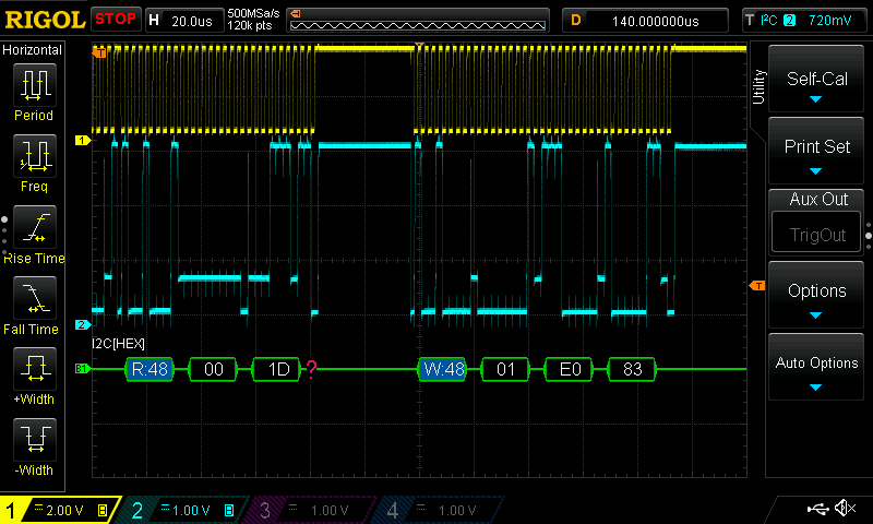
Sampling is done via I²C. First part is switching the ADC channel. Then a sleep to give the ADC time, then fetch:


uint16_t sampleADC(uint32_t uModule, UInt uSleep) {
    uint16_t uRetval = 0u;

    // ...


     a_txBuffer[1] = array_ADS1115_CFG_H[uModule];

    // ...

    /* Init ADC and Start Sampling */
    if (! I2C_transfer(i2c_implGetHandle(), &a_i2cTransaction)){
        System_printf("Sampling Start Failed \n");
    }

    // there's a pause required between channel selection and data retrieval
    // we consume that part of the task sleep time that's assigned to us by the task.
    Task_sleep(uSleep);

    // ...

    /* Read ADC */
    if (I2C_transfer(i2c_implGetHandle(), &a_i2cTransaction)) {
        uRetval = ((a_rxBuffer[0] << 8) | a_rxBuffer[1]);
    }
    else {
        System_printf("ADC Read I2C Bus fault\n");
    }

    return uRetval;
}


Reading is done via a helper function - exposed as API to the program. This can be used anytime without locking or semaphore, because the time between switching the read pointer and the next possible write in that buffer is way longer (several orders of magnitude) than calling the helper function is an atomic command.


uint16_t adcImplGetAdc(uint32_t uModule) {
    return adcRoundRobin[adcRoundRobinIndex[uModule]].raw[uModule];
}

  • Share
  • History
  • More
  • Cancel
  • Sign in to reply

Top Comments

  • Andrew J
    Andrew J over 5 years ago in reply to Jan Cumps +3
    This will be interesting - I'm creating ADC interaction with Arduino code. Have you characterised the Zero Scale Error, Full Scale Error, Offset and Gain? It would seem from my brief checking of data sheets…
  • Jan Cumps
    Jan Cumps over 5 years ago in reply to Andrew J +3
    Have you characterised the Zero Scale Error, Full Scale Error, Offset and Gain? It would seem from my brief checking of data sheets (small sample) that ADCs are better than DACs in these specs but can…
  • Jan Cumps
    Jan Cumps over 5 years ago +2
    I'm going to try and improve this part of the firmware. At this moment it's a round-robin system that has data that's between 333 ms and 1s old. That's an eternity. Code is here: https://github.com/jancumps…
  • Jan Cumps
    Jan Cumps over 5 years ago

    I've now added this feature to the released code.

    For Git and GitHub aficionados: here's how this can be done as a managed task:  Firmware Release with GitHub: Branch, Issue, Pull Request and Project support

    I've used this particular development as hook to write that post.

    • Cancel
    • Vote Up 0 Vote Down
    • Sign in to reply
    • More
    • Cancel
  • Jan Cumps
    Jan Cumps over 5 years ago

    Test was successful. Time to do the version control book keeping:


    First do a last commit to the feature branch.

    image


    Then create a pull request to the development branch


    image


    .

    Then merging (I have to use my Administrator wand because there's only one member in the repo and then I can't ask someone else to approve. Social distancing image ).

    image


    The code is now in the development branch. That's where it belongs.

    Then delete the local feature branch and switch my CCS project back to that development branch.

    Once I work on a new function, I'll do the same process: create a feature branch, do the work, commit, pull request.


    I can pull the chang from development into the main branch at a later day, when I decide to make a new release of the firmware ...

    • Cancel
    • Vote Up 0 Vote Down
    • Sign in to reply
    • More
    • Cancel
  • Jan Cumps
    Jan Cumps over 5 years ago in reply to Jan Cumps

    I have the solution.

    I compared Adafruit's init settings with mine, and the only difference is that they have the device operating mode to one shot, and I to continuous.

    When I set  one-shot too, a reliable sample, including switching the channel, can be retrieved at 9 ms.


    image

    Excellent news.


    image

    image


    The channel configuration is now (last bit from 0 to 1):

    // single conversion mode, +- 6.144V
    #define ADS1115_CFG_H0 0b11000001
    #define ADS1115_CFG_H1 0b11010001
    #define ADS1115_CFG_H2 0b11100001
    #define ADS1115_CFG_H3 0b11110001


    I need the 9 ms in the sample function, so I defined that fixed:


    #define ADS1115_MUX_DELAY 9000
    // ...


    In the sample function, the delay is put between MUXIN and reading the result:


    uint16_t sampleADC(uint32_t uModule) {
        uint16_t uRetval = 0u;
    
        /* Init ADC and Start Sampling */
        a_txBuffer[1] = array_ADS1115_CFG_H[uModule];
    
        a_txBuffer[0] = 0x01;
        a_i2cTransaction.writeCount = 3;
        a_i2cTransaction.readCount = 0;
        if (! I2C_transfer(i2c_implGetHandle(), &a_i2cTransaction)){
          //        System_printf("Sampling Start Failed \n");
        }
    
        // inspiration: https://github.com/adafruit/Adafruit_ADS1X15/blob/master/Adafruit_ADS1015.cpp
        usleep(ADS1115_MUX_DELAY);
    
        /* Read ADC */
        a_txBuffer[0] = 0x00;
        a_i2cTransaction.writeCount = 1;
        a_i2cTransaction.readCount = 2;
        if (I2C_transfer(i2c_implGetHandle(), &a_i2cTransaction)) {
            uRetval = ((a_rxBuffer[0] << 8) | a_rxBuffer[1]);
        }     else {
    //        System_printf("ADC Read I2C Bus fault\n");
        }
    
        return uRetval;
    }


    In the RTOS job, I deduct the time idled in the sample function :


    void *threadADC(void *arg0) {
        uint32_t i;
    
        a_i2cTransaction.writeBuf = a_txBuffer;
        a_i2cTransaction.readBuf = a_rxBuffer;
        a_i2cTransaction.slaveAddress = ADC_I2C_ADDR;
    
        a_txBuffer[2] = ADS1115_CFG_L;
    
        while (1)
        {
            for (i =0; i< ADC_ACTIVE_INPUTS; i++) {
                // we write value to the inactive robin
                // store value of ADC[i]
                adcRoundRobin[adcRoundRobinIndex[i] ? 0 : 1].raw[i] = sampleADC(i);
                // after value(s) written, we activate the inactive robin
                adcRoundRobinIndex[i] = adcRoundRobinIndex[i] ? 0 : 1;
            }
    
            // the thread delays ADS1115_MUX_DELAY per sample
            // so let's deduct the total delay from the requested sleep time
            usleep(THREAD_USLEEP_ADC - (ADS1115_MUX_DELAY * ADC_ACTIVE_INPUTS));
        }
    }


    I can now define the sample rate freely in RTOS, as long as the sleep time exceeds 81 ms (I sample 3 of the four ADCs, and idle 9s in each sample.

    Of course that is not precise (each line of code takes its time, in particular the two I2C communications). But good enough.


    I've set it to 100 ms (from 1 second in the past):

    void *threadADC(void *arg0);
    #define THREAD_PRIORITY_ADC 10
    // sleep has to be higher than 81000 (81 ms idled when sampling 3 ADCs
    // 100 ms : 100000 - 81000
    #define THREAD_USLEEP_ADC 19000


    Now testing with all code written and cleaed up ...

    • Cancel
    • Vote Up +1 Vote Down
    • Sign in to reply
    • More
    • Cancel
  • Andrew J
    Andrew J over 5 years ago in reply to Jan Cumps

    Ok, got it.  I was thinking of using a ramp output from a AWG - I haven’t checked much further than thinking yet!

    • Cancel
    • Vote Up +1 Vote Down
    • Sign in to reply
    • More
    • Cancel
  • Jan Cumps
    Jan Cumps over 5 years ago in reply to Jan Cumps

    Jan Cumps  wrote:


    ...

    I'll post back when I have the time to test. This may very well not work...

    I think I have to switch to single shot for the type of work I want to do ...


    edit: the longer I think about this, the less feasable:

    There's no automatic internal control of the input MUX, so I still have to call that set function to make the sampler switch channel then sample.

    Adafruit API waits 9 ms between sample and read (and they use single shot).


    ...

    Confirmed. I only get the sample value from the last channel I configured. Whatever Channel I read back.


    image

    So this was too naive. Now moving on to the Adafruit approach .....

    • Cancel
    • Vote Up 0 Vote Down
    • Sign in to reply
    • More
    • Cancel
  • Jan Cumps
    Jan Cumps over 5 years ago in reply to Andrew J
    The voltage divider you are using is going to impact the sampling accuracy of the ADC because its resistance is going to couple with the sampling capacitor and give rise to a RC time constant in charging it up between samples.


    This is a test setup to see if ADC B reports voltage from ADC A. Just that.

    Something that takes care that all 4 inputs have a different voltage level, so that I can see if the DAC doesn't accidentally report the sample of the previous channel.


    I have tools to properly drive them (either using the 4 DACs that I have available, or a low impedance voltage divider).

    Not needed here. I just need 4 voltage levels that I can recognise in the results.


    edit: the goal is to see if my timing optimisation doesn't result in reading from the wrong channel.

    • Cancel
    • Vote Up +1 Vote Down
    • Sign in to reply
    • More
    • Cancel
  • Andrew J
    Andrew J over 5 years ago

    Hi Jan,


    Over the last couple of days I've been looking at improving the results of sampling with the ADC I have (MCP3428.)  This is theory reading as I've not undertaking detailed testing yet - I really need to move off the breadboard - but it was trying to determine whether or not I should buffer the ADC inputs and put a low pass filter (for noise) in front as well to finalise my circuit and create a PCB.


    What I've gathered so far...

    The voltage divider you are using is going to impact the sampling accuracy of the ADC because its resistance is going to couple with the sampling capacitor and give rise to a RC time constant in charging it up between samples.  IIRC you are using an ADS1115 which has a MUX in front of a single ADC and it wants a low impedance source (the mux/single ADC is important because of the way that means the ADC samples across the channels and the RC constant.)  If your sampling frequency is too fast you won't give the sampling capacitor time to discharge/charge between samples and this will manifest itself as inaccuracies on the channel you are reading because it will still maintain some charge from the previous channel, or would not have had chance to charge completely.  With the voltage divider you may find a buffer useful, but then you will want to put a series resistance between its output and the ADC input.  See where that is going....In any case, it seems better to use a low pass filter between the buffer and the pin and that has the benefit of (a) giving the op amp a low capacitance load on its output; (b) a charging reservoir for the sampling capacitor to improve the possible sampling rate.  OR make sure the sampling rate - that is, the number of times you ask it to sample - is low enough to not impact the results.


    Now, let me caveat all the above by saying you know a lot more than I do about this stuff and I may be reading incorrectly into this stuff.  I've also not yet thought how the RDY pin (byte in my case) would impact that - if the sampling rate will be slowed down by waiting for that indicator which would mitigate the RC issue, but it's not clear from the datasheet that implies high impedance on the inputs impacts accuracy. 


    Here are my references:

    http://www.ti.com/lit/an/spna061/spna061.pdf

    and

    https://www.embeddedrelated.com/showarticle/110.php


    I ran through the TI paper making calculations and the embeddedrelated paper, which I came across afterwards, actually confirms the calculations I did.  I'm still at a loss to the value of the R in the low pass filter.  My calcs give it as a smidgen under 54000Ohms which is clearly wrong!  So I'm still confused on that bit.


    Hope this was of some help and hasn't been a distraction.

    • Cancel
    • Vote Up +1 Vote Down
    • Sign in to reply
    • More
    • Cancel
  • Jan Cumps
    Jan Cumps over 5 years ago in reply to Jan Cumps

    Setup: a simple voltage divider that puts a different level on each ADC:


    image

    Levels:


    image


    I'll now debug through the code, check if what the ADC reports is actually for the correct input.

    My prediction, with the code above, is: no ...

    • Cancel
    • Vote Up +1 Vote Down
    • Sign in to reply
    • More
    • Cancel
  • Jan Cumps
    Jan Cumps over 5 years ago in reply to Jan Cumps

    Untested, but compiles:


    I extracted the setup and moved it out of the sample function, together with everything in the Tx buffer that's constant over the lifecycle:


        /* Init ADC and Start Sampling */
        a_i2cTransaction.writeCount = 3;
        a_i2cTransaction.readCount = 0;
        a_txBuffer[0] = 0x01;
        a_txBuffer[2] = ADS1115_CFG_L;
    
        for (i =0; i< ADC_ACTIVE_INPUTS; i++) {
          a_txBuffer[1] = array_ADS1115_CFG_H[i];
          if (! I2C_transfer(i2c_implGetHandle(), &a_i2cTransaction)){
            //        System_printf("Sampling Start Failed \n");
          }
        }
    
        a_txBuffer[0] = 0x00;
        a_i2cTransaction.writeCount = 1;
        a_i2cTransaction.readCount = 2;


    Then, the only part of ADC traffic that's in the loop is a call of this function per channel (this is all that's left from the function in the previous comment):


    uint16_t sampleADC(uint32_t uModule) {
        uint16_t uRetval = 0u;
    
        a_txBuffer[1] = array_ADS1115_CFG_H[uModule];
    
        /* Read ADC */
        if (I2C_transfer(i2c_implGetHandle(), &a_i2cTransaction)) {
            uRetval = ((a_rxBuffer[0] << 8) | a_rxBuffer[1]);
        }
        else {
    //        System_printf("ADC Read I2C Bus fault\n");
        }
    
        return uRetval;
    }


    I'll post back when I have the time to test. This may very well not work...

    I think I have to switch to single shot for the type of work I want to do ...


    edit: the longer I think about this, the less feasable:

    There's no automatic internal control of the input MUX, so I still have to call that set function to make the sampler switch channel then sample.

    Adafruit API waits 9 ms between sample and read (and they use single shot).


    The datasheet says:

    image


    There's a pin that tells what a sample is ready. It's unused in the eLoad.

    I didn't want to tie it to  a microcontroller pin, because that would break the isolation that we've designed.


    I could have attached it to one of the pins of the i2c port extender, in hindsight.

    .....


    image

    • Cancel
    • Vote Up +1 Vote Down
    • Sign in to reply
    • More
    • Cancel
  • Jan Cumps
    Jan Cumps over 5 years ago

    My first remarks, after reading the datasheet and looking at my own code:


    uint16_t sampleADC(uint32_t uModule, uint32_t uSleep) {
        uint16_t uRetval = 0u;
    
        /* Point to the ADC ASD1115 and read input uModule */
        a_i2cTransaction.writeCount = 3;
        a_i2cTransaction.readCount = 0;
        a_txBuffer[0] = 0x01;
        a_txBuffer[1] = array_ADS1115_CFG_H[uModule];
    
        /* Init ADC and Start Sampling */
        if (! I2C_transfer(i2c_implGetHandle(), &a_i2cTransaction)){
    //        System_printf("Sampling Start Failed \n");
        }
    
    
        // there's a pause required between channel selection and data retrieval
        // we consume that part of the task sleep time that's assigned to us by the task.
        usleep(uSleep);
    
        a_txBuffer[0] = 0x00;
        a_i2cTransaction.writeCount = 1;
        a_i2cTransaction.readCount = 2;
        /* Read ADC */
        if (I2C_transfer(i2c_implGetHandle(), &a_i2cTransaction)) {
            uRetval = ((a_rxBuffer[0] << 8) | a_rxBuffer[1]);
        }
        else {
    //        System_printf("ADC Read I2C Bus fault\n");
        }
    
        return uRetval;
    }


    At each sample attempt, I

    • configure a channel
    • wait
    • sample the channel


    image


    While I think I can move this one to the initial setup, outside the sample loop:

    • configure a channel


    I can skip this one

    • wait


    And keep only this inside the loop:

    • sample the channel


    It's a little late in the evening to test this. But if that's it, it would be an easy change ...

    • Cancel
    • Vote Up +1 Vote Down
    • Sign in to reply
    • More
    • Cancel
>
element14 Community

element14 is the first online community specifically for engineers. Connect with your peers and get expert answers to your questions.

  • Members
  • Learn
  • Technologies
  • Challenges & Projects
  • Products
  • Store
  • About Us
  • Feedback & Support
  • FAQs
  • Terms of Use
  • Privacy Policy
  • Legal and Copyright Notices
  • Sitemap
  • Cookies

An Avnet Company © 2025 Premier Farnell Limited. All Rights Reserved.

Premier Farnell Ltd, registered in England and Wales (no 00876412), registered office: Farnell House, Forge Lane, Leeds LS12 2NE.

ICP 备案号 10220084.

Follow element14

  • X
  • Facebook
  • linkedin
  • YouTube