


Table of Contents
Introduction
In this blog, we'll see how the integration of functionalities of Cortex M0 and Cortex M4 core and done by bringing in together the bits and pieces that I've demonstrated in the previous blogs. Starting off with this project majorly includes 4 functionalities, one being the Capsense touch and slider, ambient light sensor and temperature sensors, the LED bar indication based on the sensor data and the inter-process communication pipe. Also, the serial UART message transmission based on core activity is included in this.
As per the agenda of this At The Core Design Challenge, I've attempted to use both the cores and tried to use up to their limits, with user control utilizing CapSense, Motor control using multichannel PWM signal, all done inside Cortex M0 core. The next Cortex M4 4 interlinks with Cortex M0+ and they work interchangeably using lock/unlocking of semaphore and communicate through the IPC pipeline. Running on Cortex M4 is the LED bar indication based on the sensor data acquired. This also does the motor control signal transmission based on the ambient light sensor data.
The application which I am thinking of here is the automated curtain control. Data acquired from the light sensor - if it is greater than a certain threshold that is of the light coming from the window or within the room, then the Cortex M4 core will sense that particular limit and send the motor control initiation command to Cortex M0+ through IPC pipeline. Cortex M0 realising this data will activate the motor control and enable the user to use the Capsense utilities for doing this process. So let's look deeper into the builds and the whole firmware flow.
Linking CM0+ and CM4 tasks
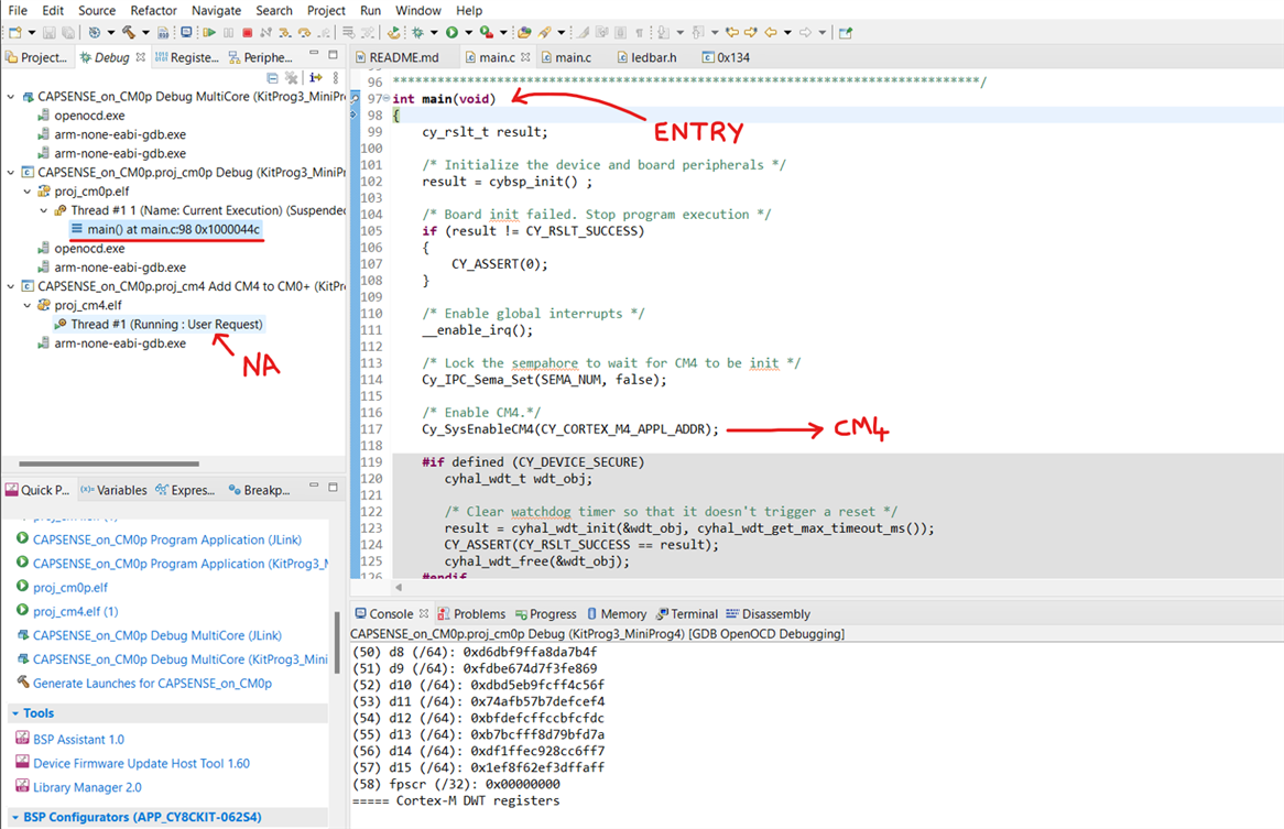
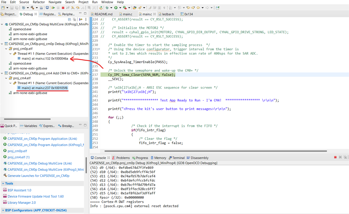
Two are separate system cores running at different speeds. The tasks are tested individually for each core and one of the smart methods used in one of the example applications is the usage of semaphores to lock/unlock the task accordingly and sequentially run the tasks without collisions. We know what happens when a task is overridden or breaks in the process of execution. Using this locking method, the code is built on and it is clearly visualized in the dual-core application debug more which is quite a lot interesting and I spent quite some time clicking through and getting to know the flow. Here's the flowchart for this application having multi-peripherals coming to action.
Starting with CM0+, the control is given to CM4 which does one set of initial processes and acts back enabling CM0+ again. The processes all after this run seemingly in parallel - really? No! but quite fluently handling the lock/unlock processes. The pushbutton is optionally kept for critical tasks which are locked/unlocked by semaphores to which the access is through a pushbutton press.
Testing both the Cores Simultaneously


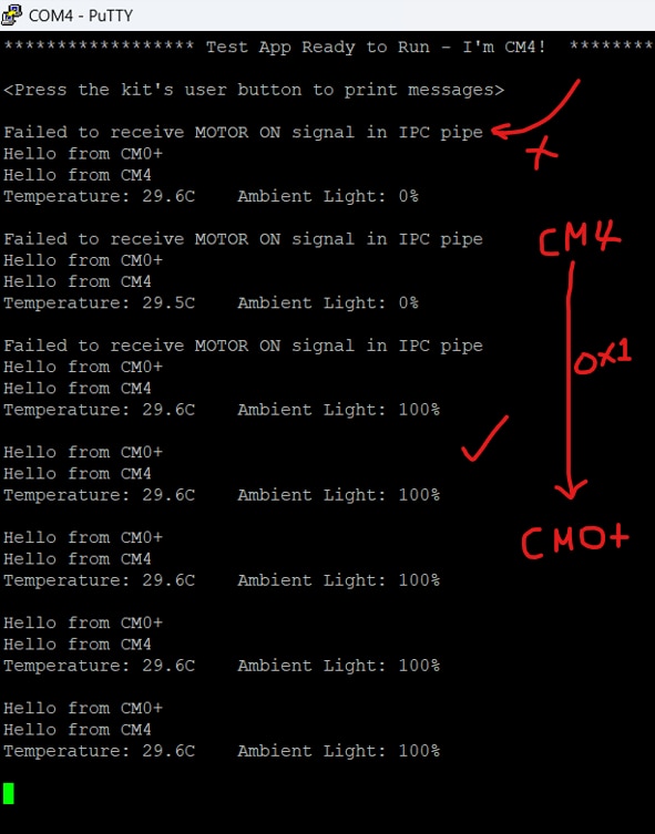
IPC piping and exchanging messages for motor control
Uptil here, the cores ran their tasks and the usage of semaphore is seen to schedule tasks and run in sequence. Now, the challenge I came across is to transmit the data acquired from the light sensor to the motor control. These two tasks are in separate cores and I thought of having extern variable? Or would a variable be common for cores in dual-core application? No! And here comes the PIC pipe for the save. In the IPC driver layer, certain APIs are exposed and a pair of them is Cy_IPC_Drv_SendMsgWord() and Cy_IPC_Drv_SendMsgWord(). It assumes that the function is locked and thus does the IPC - so the user have to take care of lock/unlock before and after this process. However, in the earlier implementation, there is a semaphore lock and so these functions are also called in the same with some error handling:
CM0+ side
uint32_t myMsg; /* reception message variable */


/*MOTOR control state receive*/
IPC_STRUCT_Type * myIpc = Cy_IPC_Drv_GetIpcBaseAddress(MY_IPC_CHAN_INDEX); /* Get IPC base register address */
if ((CY_IPC_DRV_SUCCESS == Cy_IPC_Drv_ReadMsgWord(myIpc, &myMsg)) && (myMsg ==0x01))
{
    /* Now myMsg contains the received message word */
    /* The IPC data is received and processed.
     * Free up the channel for the next transaction.
     */
    	/*Allow MOTOR1 control ON*/
	    cyhal_gpio_write(CYBSP_A8, HIGH);
	    cyhal_gpio_write(CYBSP_A9, HIGH);

    Cy_IPC_Drv_ReleaseNotify(myIpc, MY_IPC_INTR_MASK);
}
else
{
    /* Insert error handling */
    Cy_SCB_UART_PutString(CYBSP_UART_HW, "Failed to receive MOTOR signal in IPC pipe\r\n");

    /*Inhibit motor action*/
    cyhal_gpio_write(CYBSP_A8, LOW);
    cyhal_gpio_write(CYBSP_A9, LOW);
    cyhal_system_delay_ms(500);
}
CM4 side
uint32_t myMsg = 0x00;

/*Motor ON full speed if ALS > 60% using IPC pipe*/
if(light_intensity >= ALS_THRESH_LEVEL6)
{
	IPC_STRUCT_Type * myIpc = Cy_IPC_Drv_GetIpcBaseAddress(MY_IPC_CHAN_INDEX); /* Get IPC base register address */
	myMsg = 0x1;        /* MOTOR control ON message */
	if (CY_IPC_DRV_SUCCESS != Cy_IPC_Drv_SendMsgWord(myIpc, MY_IPC_INTR_MASK, myMsg))
	{
		/* Insert error handling */
		printf("Failed to send MOTOR control ON signal in IPC pipe\r\n");
        cyhal_system_delay_ms(500);
	}
}
So in the below serial view, initially the MOTOR control ON message is not received and then whenever the light intensity is above 60% as set in the threshold, 0x01 message is sent in the pipe that is received on CM0+ side and allows the user to have button and PWM control of the motor. The idea with this is to pull the window curtain close when the light intensity is going too high by motorising it.
Comparing % Memory Usage
Ok, time to see how much memory this application has utilized in each core and is it close to its full potential?
CM4
Calculating memory consumption: CY8C6244LQI-S4D92 GCC_ARM
----------------------------------------------------
| Section Name | Address | Size |
----------------------------------------------------
| .text | 0x10010000 | 37680 |
| .ARM.exidx | 0x10019330 | 8 |
| .copy.table | 0x10019338 | 24 |
| .zero.table | 0x10019350 | 8 |
| .data | 0x080102fc | 1652 |
| .cy_sharedmem | 0x08010970 | 8 |
| .noinit | 0x08010978 | 228 |
| .bss | 0x08010a5c | 1188 |
| .heap | 0x08010f00 | 55552 |
----------------------------------------------------
Total Internal Flash (Available) 262144
Total Internal Flash (Utilized) 39388
CM0+
Calculating memory consumption: CY8C6244LQI-S4D92 GCC_ARM
----------------------------------------------------
| Section Name | Address | Size |
----------------------------------------------------
| .text | 0x10000000 | 32152 |
| .ARM.exidx | 0x10007d98 | 8 |
| .copy.table | 0x10007da0 | 24 |
| .zero.table | 0x10007db8 | 8 |
| .data | 0x08000080 | 1256 |
| .cy_sharedmem | 0x08000568 | 24 |
| .noinit | 0x08000580 | 140 |
| .bss | 0x0800060c | 1096 |
| .heap | 0x08000a58 | 58792 |
----------------------------------------------------
Total Internal Flash (Available) 262144
Total Internal Flash (Utilized) 33480
So overall, CM4 has utilized 15.02% of flash and CM0+ is at 12.77%. I also explored about processor usage - just like we measure CPU speed and usage in PC, but couldn't find an exact method to gauge that. Is it still a feature in MCUs and embedded devices? Not sure if i have seen them in any...
Code
https://github.com/NavadeepGaneshU/AtTheCore_DesignChallenge_PSoC62S4

Future Work
Thanks for reading through and hope it was interesting for you all. It was fun working on this project and a super interesting challenge. Dual-core MCUs pose for some very good use cases and with the tools provided by Infineon, the learning curve is attempted to be brought flatter yet the documentation is quite verbose and a lot more things to explore with this kit for me. This project application can be further extended by adding audio intelligence with ML toolbox to implement a door security system with audio/video auth and a plethora of sensors to monitor safety - yet not limited. Looking forward for opportunities like this and I'll be up with this project and will likely be using this device for my upcoming designs.
References
Also Read
AtTheCore: Blog #1 - Intro and what's up with the kit!
AtTheCore: Blog #2 - Interfacing LED Bar with ALS
AtTheCore: Blog #3 - PWM and Capsense on Cortex M0+
AtTheCore: Blog #4 - Adding shared PWM, Testing with Scope and all about Dual-Core

