


Title: Vital Care
By: Md. Kamrul Hussain
Project Category: Design Challenge
Project Name: Design For A Cause 2021
Blog post: 08
Previous Blogs:
|
Blog No. |
Title |
|---|---|
| 01 |
Introduction |
| 02.a |
SPO2 basics [PPG] |
| 02.b | SPO2 [MAX30102] |
| 03 | Temperature |
| 04 | ECG [AD8232 single LEAD] |
| 05 | Respiration |
| 06 | IOT Cloud Integration |
Project Goal:
The project goal was to design a continuous vital monitoring device which can ease the Post recovery after care process for CoVid - 19. This device will send the health parameter into the cloud for telemedicine.
Point of Interest:
- Heart -
ECG LEAD 1 is acquired and Heart Beat rate is calculated.
This can be useful to detect potential threat due to Heart Rate Variability.
- Lungs -
SpO2 is calculated from PPG signals. This can provide early detection of long-standing damage to the tiny air sacs (alveoli) in the lungs. This may lead to long-term breathing problems.
Respiratory signal is derived from ECG signal using R-peak amplitude variation during exhale and inhale. This can provide information on pulmonary disease.
Vital Signs to be monitored:
-
-
- PPG - provides oxygen saturation in blood [SpO2] - √
-
- ECG LEAD1 - provides heart beat rate - √
-
- Respiratory signal derived from ECG - √
-
- Temperature - √
-

Objectives Achieved:
Module01 -
- AD8232 gives ECG LEAD1
- Arduino MKR WiFi 1010 successfully process the LEAD1 ECG signal
- Calculates Heart Rate successfully
- Conditions the ECG signal to emphasize R-PEAK amplitude
- Derive respiratory signal from the R-PEAK variation
- send Heart Rate, Lead off detection and Respiratory signal to Arduino IOT Cloud
Related Blogs:
Vital Care - 04 ECG [AD8232 single LEAD]


Code snippets:
#include "arduino_secrets.h"
#include "thingProperties.h"
/*
  Sketch generated by the Arduino IoT Cloud Thing "Vital Care chest"
  https://create.arduino.cc/cloud/things/9e5d4ff0-fa15-41f8-bc4f-81f9bfee5ea0


  Arduino IoT Cloud Variables description


  The following variables are automatically generated and updated when changes are made to the Thing


  float RESP;
  float heartRate;
  bool ecgLEAD;


  Variables which are marked as READ/WRITE in the Cloud Thing will also have functions
  which are called when their values are changed from the Dashboard.
  These functions are generated with the Thing and added at the end of this sketch.
*/


#include <Ewma.h>
#include <EwmaT.h>
#include "KickFiltersRT.h"


Ewma adcFilter1(0.1);   // Less smoothing - faster to detect changes, but more prone to noise
Ewma adcFilter2(0.1);  // More smoothing - less prone to noise, but slower to detect changes


const float sinefreq = 50;
const float fs = 15*sinefreq; //samples 15x the frequency of the wave
const float dt = 1.0/fs;
const uint16_t samples = 20*(1/sinefreq)/dt; //prints 20 cycles of the wave


const float scale = 100;


int16_t input0;
int16_t input;
byte count = 1;


bool LEADstatus = 1;
bool QRSstart = 0;
unsigned long starttime = 0;
unsigned long stoptime = 0;
unsigned long Rtime = 0;
unsigned long R0time = 0;
float beats0 = 0;
float peak = 0;
float peak0 = 0;
float beatrate, beatrate0;
float resp, resp0;


float filtered1;
float filtered2, filtered2_0;

float derivative;
float square, square0;
float beats;


#define GND A1
#define POWER A2
#define ECGOUT A3
#define LO_LA A4
#define LO_RA A5
#define SDN A6


KickFiltersRT<float> filtersRT;
KickFiltersRT<int16_t> filtersRT1;
KickFiltersRT<int16_t> filtersRT2;
KickFiltersRT<int16_t> filtersRT3;


void setup() {
  // Initialize serial and wait for port to open:
  Serial.begin(9600);
  // This delay gives the chance to wait for a Serial Monitor without blocking if none is found
  delay(1500);


  //setting your own r_coeff value
  filtersRT1.initnotch(0, 0, 50, fs, 0.8);
  filtersRT.inithighpass(input, 0.5, fs);


  R0time = millis();


  //Initialize AD8232 module
  pinMode(GND, OUTPUT);     //PROVIDE GROUND [0V] TO AD8232 MODULE
  pinMode(POWER, OUTPUT);   //PROVIDE POWER [3.3V] TO AD8232 MODULE
  pinMode(LO_LA, INPUT);
  pinMode(LO_RA, INPUT);
  pinMode(SDN, OUTPUT);
  pinMode(LED_BUILTIN, OUTPUT);

  digitalWrite(GND,LOW);
  digitalWrite(POWER,HIGH);
  digitalWrite(SDN,HIGH);

  // Defined in thingProperties.h
  initProperties();


  // Connect to Arduino IoT Cloud
  ArduinoCloud.begin(ArduinoIoTPreferredConnection);

  /*
     The following function allows you to obtain more information
     related to the state of network and IoT Cloud connection and errors
     the higher number the more granular information you’ll get.
     The default is 0 (only errors).
     Maximum is 4
 */
  setDebugMessageLevel(2);
  ArduinoCloud.printDebugInfo();
}


void loop() {
  ArduinoCloud.update();
  // Your code here


while(digitalRead(LO_LA) && digitalRead(LO_RA)){
    digitalWrite(LED_BUILTIN, HIGH);
     LEADstatus = 0;
     ecgLEAD = LEADstatus;
     delay(500);
  }
  digitalWrite(LED_BUILTIN,LOW);
  LEADstatus = 1;

  for(uint16_t i = 0; i < samples; i++)
  {
    input = analogRead(ECGOUT);

    float filtered1 = adcFilter1.filter(input);
    float filtered2 = filtersRT.highpass(filtered1);

    float derivative = filtered2 - input0;
    input0 = filtered2;
    float square = sq(derivative);
    float beats = adcFilter2.filter(square);
    //float resp = adcFilter3.filter(beats);


    if (beats > 50 && QRSstart == 0){
      QRSstart = 1;
      starttime = millis();
      beats0 = beats;
    }
    if (beats > 50 && QRSstart == 1 && beats > beats0){
      beats0 = beats;
      Rtime = millis();
    }
    if (beats < 50 && QRSstart == 1){
      QRSstart = 0;
      stoptime = millis();
      if (stoptime - starttime > 40){
        beatrate = 60000 / (Rtime - R0time);
        R0time = Rtime;
        resp = beats0 / 2;


        if (resp > 1000 || resp < 0){
          resp = resp0;
          }
        if (beatrate > 200 || beatrate < 0){
          beatrate = beatrate0;
          }
        Serial.print(beatrate);
        Serial.print(",");
        Serial.print(resp);
        Serial.println();


        RESP = resp;
        heartRate = beatrate;
        ecgLEAD = LEADstatus;


      }

     resp0 = resp;
     beatrate0 = beatrate;
    }
  }
}
Module02 -
- MAX30102 gives PPG for IR and RED LEDs
- Built-in Temperature sensor inside the MAX30102 provides body temperature output
- NANO 33 IOT calculates the SPO2 from IR and RED LedsConditions t
- Sends Temperature and Respiratory signal to Arduino IOT Cloud
Related Blogs:
Vital Care - 02.a SPO2 basics [PPG]
Vital Care - 02.b SPO2 [MAX30102]


Code snippets:
#include "arduino_secrets.h"
#include "thingProperties.h"
/*
  Sketch generated by the Arduino IoT Cloud Thing "SunnyiutThing"
  https://create.arduino.cc/cloud/things/2ccb6449-f4b8-4fc3-b016-19ef812cce18


  Arduino IoT Cloud Variables description


  The following variables are automatically generated and updated when changes are made to the Thing


  CloudHeartRate HR;
  bool placeFinger;
  CloudHeartRate RespRate;
  CloudPercentage oxi;
  float TEMP;
  float RESP;

  Variables which are marked as READ/WRITE in the Cloud Thing will also have functions
  which are called when their values are changed from the Dashboard.
  These functions are generated with the Thing and added at the end of this sketch.
*/


#include <Ewma.h>
#include <EwmaT.h>
Ewma adcFilter2(0.1);
Ewma adcFilter1(0.07);


#include <heartRate.h>
#include <MAX30105.h>
#include <spo2_algorithm.h>


MAX30105 particleSensor;


#define MAX_BRIGHTNESS 255


uint32_t irBuffer[100]; //infrared LED sensor data
uint32_t redBuffer[100];  //red LED sensor data


int32_t bufferLength; //data length
int32_t spo2; //SPO2 value
int8_t validSPO2; //indicator to show if the SPO2 calculation is valid
int32_t heartRate; //heart rate value
int8_t validHeartRate; //indicator to show if the heart rate calculation is valid


float temperature;
float filtered1;
float filtered2;


int32_t finger; //finger presence


byte pulseLED = 13; //Must be on PWM pin
byte readLED = 9; //Blinks with each data read


void setup() {
  // Initialize serial and wait for port to open:
  Serial.begin(9600);
  // This delay gives the chance to wait for a Serial Monitor without blocking if none is found
  delay(5000);

  pinMode(pulseLED, OUTPUT);
  pinMode(readLED, OUTPUT);

  // Defined in thingProperties.h
  initProperties();


  // Connect to Arduino IoT Cloud
  ArduinoCloud.begin(ArduinoIoTPreferredConnection);

  /*
     The following function allows you to obtain more information
     related to the state of network and IoT Cloud connection and errors
     the higher number the more granular information you’ll get.
     The default is 0 (only errors).
     Maximum is 4
 */
  setDebugMessageLevel(2);
  ArduinoCloud.printDebugInfo();

//-------------------------------------------------------------------------------------


  // Initialize sensor
  if (!particleSensor.begin(Wire, I2C_SPEED_FAST)) //Use default I2C port, 400kHz speed
  {
    Serial.println(F("MAX30105 was not found. Please check wiring/power."));
    while (1);
  }


  //confiure MAX30102
  byte ledBrightness = 47; //Options: 0=Off to 255=50mA
  byte sampleAverage = 4; //Options: 1, 2, 4, 8, 16, 32
  byte ledMode = 2; //Options: 1 = Red only, 2 = Red + IR, 3 = Red + IR + Green
  byte sampleRate = 100; //Options: 50, 100, 200, 400, 800, 1000, 1600, 3200
  int pulseWidth = 411; //Options: 69, 118, 215, 411
  int adcRange = 4096; //Options: 2048, 4096, 8192, 16384

  particleSensor.setup(ledBrightness, sampleAverage, ledMode, sampleRate, pulseWidth, adcRange); //Configure sensor with these settings

  particleSensor.enableDIETEMPRDY(); //Enable the temp ready interrupt. This is required.
}


void loop() {

bufferLength = 100; //buffer length of 100 stores 4 seconds of samples running at 25sps


  //read the first 100 samples, and determine the signal range
  for (byte i = 0 ; i < bufferLength ; i++)
  {
    while (particleSensor.available() == false) //do we have new data?
      particleSensor.check(); //Check the sensor for new data


    redBuffer[i] = particleSensor.getRed();
    irBuffer[i] = particleSensor.getIR();
    particleSensor.nextSample(); //We're finished with this sample so move to next sample


    Serial.print(F("red="));
    Serial.print(redBuffer[i], DEC);
    Serial.print(F(", ir="));
    Serial.println(irBuffer[i], DEC);
  }


  //calculate heart rate and SpO2 after first 50 samples (first 2 seconds of samples)
  maxim_heart_rate_and_oxygen_saturation(irBuffer, bufferLength, redBuffer, &spo2, &validSPO2, &heartRate, &validHeartRate);
  heartRate = heartRate / 2;

  //Continuously taking samples from MAX30102.  Heart rate and SpO2 are calculated every 1 second
  while (1)
  {
    //dumping the first 25 sets of samples in the memory and shift the last 75 sets of samples to the top
    for (byte i = 25; i < 100; i++)
    {
      redBuffer[i - 25] = redBuffer[i];
      irBuffer[i - 25] = irBuffer[i];
    }

    //take 25 sets of samples before calculating the heart rate.
    for (byte i = 75; i < 100; i++)
    {
      while (particleSensor.available() == false) //do we have new data?
        particleSensor.check(); //Check the sensor for new data


      digitalWrite(readLED, !digitalRead(readLED)); //Blink onboard LED with every data read


      redBuffer[i] = particleSensor.getRed();
      irBuffer[i] = particleSensor.getIR();
      finger = (finger + irBuffer[i]) / 2;

      particleSensor.nextSample(); //We're finished with this sample so move to next sample


      //send samples and calculation result to terminal program through UART
      Serial.print(F("RED= "));
      Serial.print(redBuffer[i], DEC);
      Serial.print('\t');

      Serial.print(F("IR= "));
      Serial.print(irBuffer[i], DEC);
      Serial.print('\t');


      Serial.print(F("HR= "));
      Serial.print(heartRate, DEC);
      Serial.print('\t');


      filtered1 = adcFilter1.filter(irBuffer[i]);
      filtered2 = adcFilter2.filter(filtered1);


      Serial.print(F("filtered1= "));
      Serial.print(filtered1);
      Serial.print('\t');

      Serial.print(F("filtered2= "));
      Serial.print(filtered2);
      Serial.print('\t');


      Serial.print(F("SPO2= "));
      Serial.print(spo2, DEC);
      Serial.print('\t');

      temperature = particleSensor.readTemperature();
      Serial.print(F("temperatureC= "));
      Serial.println(temperature, 4);
    }


    //After gathering 15 new samples recalculate HR and SP02
    maxim_heart_rate_and_oxygen_saturation(irBuffer, bufferLength, redBuffer, &spo2, &validSPO2, &heartRate, &validHeartRate);


    heartRate = heartRate * 0.5;
    if(finger < 70000 or validSPO2 < 1 or validHeartRate < 1)
    {
      placeFinger = 0;
      HR = 0;
      oxi = 0;
    }
    else
    {
      placeFinger = 1;
      HR = heartRate;
      oxi = spo2;
    }
    TEMP = temperature;
    RESP = filtered2;


    digitalWrite(readLED, 1);
    ArduinoCloud.update();
    digitalWrite(readLED, 0);
  }

}
Module03 -
Data is sent to Arduino IOT Cloud by both Module 01 and Module 02 simultaneously.

Related Blogs:
Experimental Setup:
| {gallery} Prototype |
|---|
|
Prototype: Experimental Setup |
|
Chest belt: ECG [AD8232] and MKR WiFi 1010 |
|
Module 2: SpO2 experimental setup |


Update:
I could not get chance to post some updates of the project. Having a busy time, can't get enough time to make a video on the final device. Hopefully, I'll post a video this week.
However,
This update [11 June] is on the android app to show the sensor data, using Blynk. The app is titled as Vital Care with two modules [Vital Care Chest and Vital Care Wrist] connected and send data simultaneously. Unfortunately the chest device needs to take sample of large amount of ADC data to apply filters and QRS detection algorithm. Sometimes, Blynk gets stuck and takes large time to communicate and ADC can't sample the higher frequency components of the ECG signal. This results into missing heart beats!! I have attached some screenshots of the App below.
App for Vital Care sensor data monitoring [using BLYNK]-
| {gallery} Blynk_Vital Care APP |
|---|
|
Blynk Dashboard: Screenshots of the Blynk-Vital Care App presenting data on Heart rate, SpO2 level, Temperature etc. Plots respiratory signal, continuous heart rate, continuous SpO2. [these screens showing data from module 01 only] It also presents LED indicators for PPG sensor placement and ECG LEAD OFF detection. RED LED turns on if the MAX30102 sensor is not placed properly and if the ECG electrodes are disconnected. |
|
Heart Rate settings: Gauge settings of the Heart Rate - taking input from VitalCareChest device [module 01 - MKR WiFi 1010 - AD8232] at virtual pin V2 |
|
SpO2 settings: Gauge settings of the Oxygen Saturation Level - taking input from VitalCareWrist device [module 02 - NANO 33 IOT - MAX30102] at virtual pin V4 |
|
Temperature settings: Gauge settings of the Body Temperature Level - taking input from VitalCareWrist device [module 02 - NANO 33 IOT - MAX30102] at virtual pin V5 |
|
Chart settings: settings for plotting continuous SpO2, Heart Rate and live Respiratory signals on SuperChart |
|
PPG Placement settings: LED settings of the PPG placement - taking input from VitalCareWrist device [module 02 - NANO 33 IOT - MAX30102] at virtual pin V6 |
|
ECG LEAD OFF settings: LED settings of the LEAD OFF - taking input from VitalCareChest device [module 01 - MKR WiFi 1010 - AD8232] at virtual pin V3 |
|
Device settings: VitalCareChest represents Module 01 and VitalCareWrist represents Module 02. Both the devices are initialized as Arduino NANO hardware model with WiFi connectivity. |


code snippets -
Module 01 - VitalCareChest: [represents the main loop part ]
Blynk.run();
  timer.run(); // Initiates BlynkTime


  if(digitalRead(LO_LA) || digitalRead(LO_RA)){
    digitalWrite(LED_BUILTIN, HIGH);
     LEADstatus = 255;
     Blynk.virtualWrite(V3, LEADstatus);
    Serial.println("LEADoff");
  }
  else{
    digitalWrite(LED_BUILTIN,LOW);
  LEADstatus = 0;
  Blynk.virtualWrite(V3, LEADstatus);
  }

  for(uint16_t i = 0; i < samples; i++)
  {
    input = analogRead(ECGOUT);

    float filtered1 = adcFilter1.filter(input);
    float filtered2 = filtersRT.highpass(filtered1);

    float derivative = filtered2 - input0;
    input0 = filtered2;
    float square = sq(derivative);
    float beats = adcFilter2.filter(square);


    if (beats > 40 && QRSstart == 0){
      QRSstart = 1;
      starttime = millis();
      beats0 = beats;
    }
    if (beats > 40 && QRSstart == 1 && beats > beats0){
      beats0 = beats;
      Rtime = millis();
    }
    if (beats < 40 && QRSstart == 1){
      QRSstart = 0;
      stoptime = millis();
      if (stoptime - starttime > 40){
        beatrate = 60000 / (Rtime - R0time);
        R0time = Rtime;
        //resp = beats0 / 2;
        resp = beats0;

        if (resp > 2000 || resp < 0){
          resp = resp0;
          }
        if (beatrate > 200 || beatrate < 0){
          beatrate = beatrate0;
          }
        Blynk.virtualWrite(V1, resp);
        Blynk.virtualWrite(V2, beatrate);

       }
    }
  count++;
   if (count > 7){
  Serial.print(input);
     Serial.print(",");
   Serial.print(beatrate);
     Serial.print(",");
     Serial.print(filtered2);
     Serial.println();
     count = 0;}

  }
Module 02 - VitalCareWrist: [represents the main loop part ]
Blynk.run();
  timer.run(); // Initiates BlynkTime


//dumping the first 25 sets of samples in the memory and shift the last 15 sets of samples to the top
    for (byte i = 25; i < 100; i++)
    {
      redBuffer[i - 25] = redBuffer[i];
      irBuffer[i - 25] = irBuffer[i];
    }

    //take 25 sets of samples before calculating the heart rate.
    for (byte i = 75; i < 100; i++)
    {
      while (particleSensor.available() == false) //do we have new data?
        particleSensor.check(); //Check the sensor for new data


      digitalWrite(readLED, !digitalRead(readLED)); //Blink onboard LED with every data read


      redBuffer[i] = particleSensor.getRed();
      irBuffer[i] = particleSensor.getIR();
      finger = (finger + irBuffer[i]) / 2;

      particleSensor.nextSample(); //We're finished with this sample so move to next sample


      //send samples and calculation result to terminal program through UART
      Serial.print(F("RED= "));
      Serial.print(redBuffer[i], DEC);
      Serial.print('\t');

      Serial.print(F("IR= "));
      Serial.print(irBuffer[i], DEC);
      Serial.print('\t');


      Serial.print(F("HR= "));
      Serial.print(heartRate, DEC);
      Serial.print('\t');


      filtered1 = adcFilter1.filter(irBuffer[i]);
      filtered2 = adcFilter2.filter(filtered1);


      Serial.print(F("filtered1= "));
      Serial.print(filtered1);
      Serial.print('\t');

      Serial.print(F("filtered2= "));
      Serial.print(filtered2);
      Serial.print('\t');


      //Serial.print(F(", HRvalid="));
      //Serial.print(validHeartRate, DEC);


      Serial.print(F("SPO2= "));
      Serial.print(spo2, DEC);
      Serial.print('\t');

      //Serial.print(F(", SPO2Valid="));
      //Serial.print(validSPO2, DEC);

      temperature = particleSensor.readTemperature();
      Serial.print(F("temperatureC= "));
      Serial.println(temperature, 4);
    }


    //After gathering 25 new samples recalculate HR and SP02
    maxim_heart_rate_and_oxygen_saturation(irBuffer, bufferLength, redBuffer, &spo2, &validSPO2, &heartRate, &validHeartRate);


    heartRate = heartRate * 0.5;
    if(finger < 70000 or validSPO2 < 1 or validHeartRate < 1)
    {
      finger = 255;
      spo2 = spo2_previous;
    }
    else
    {
      finger = 0;
      spo2_previous = spo2;
      //RESP = filtered2;
    }
Output-
Recorded screen [Gif- 5fps] is shared below. At one point I removed the ECG electrode jack and the app showed LED OFF. It again comes to normal operation when the jack is plugged in again. During period the device was disconnected for a few seconds and the at the end two missing beats are observed due to the latency of the communication between app and device.

Final Setup [Module 01 - chest belt]:
| {gallery} Module 01- chest belt |
|---|
|
Module 01 - chest belt: wearable boxed device [MKR WiFi 1010 with AD8232 and LiPo Battery 1s] with electrodes placed around the chest using a strap / belt |
|
Module 01 - chest belt: wearable device with electrodes placed around the chest using a strap / belt - upper cover is removed to get the inner view |
|
Module 01 - chest belt construction: The chest belt has elastic strap to firmly place the electrodes on the skin. Adjustable side release buckle is used to mount the belt on different body shapes. A horizontal velcro is sewed to mount the electrodes at any position along the chest line. |
|
Module 01 - electrode construction: for long term use, wet/gel based one time Ag-AgCl elecrodes are not suitable. so, dry electrodes are made using plated metallic conductive fabrics. Sewed using conductive threads. The conductive fabric is folded to its half. |
|
Module 01 - electrode construction: polyurethane foam is placed to give a pillow shape which can be helpful to provide a uniform contact to the body skin |
|
Module 01 - electrode construction: polyurethane foam is covered with copper foil tape where the cable is soldered. this ensures a wide area to be connected to the cable with the conductive fabric. |
|
Module 01 - electrode construction: sewing the outline with conductive thread. General purpose threads can be used too, i used conductive thread to test if I can get a good ECG signal using the thread only, leaving out the connecting cables. Experiment was successful, but equal resistance needs to be ensured. |
|
Module 01 - electrode construction: Small piece of velcro is sewed on the backside so that the electrode can be placed on the innerside of the chest belt at any position on the chest line. |


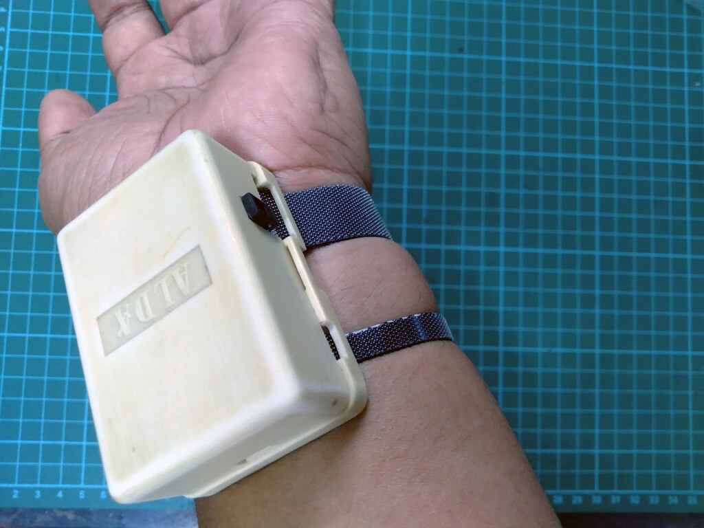
Final Setup [Module 02 - wrist]:
| {gallery} Vital Care Wrist |
|---|
|
Module 02 - Components: Separate modules and boards - veroboard base, Arduino NANO 33 IOT, battery charger, Li-Ion 170 mAH battery |
|
Module 02 - Components: Arduino NANO 33 IOT placed on the base board which contains a power switch and the DC input socket for charging the battery |
|
Module 02 - Components: The charger is placed on the Arduino NANO 33 IOT |
|
Module 02 - Sensor: MAX 30102 PPG sensor module is placed within a cut piece of the veroboard. the whole assembly is placed inside a telephone line adapter box |
|
Module 02 - Sensor: A velcro is placed around the MAX30102 sensor module to fasten the box around the wrist |
|
Module 02 - Assembling: All the boards and the sensor module with battery are assembled within the customised box |
|
Module 02 - Assembling: Fully assembled module 02 with the circuit turned on using the included battery |
|
Module 02 - Assembling: Top side of the module 02 box |
|
Module 02 - Assembling: Bottom side of the module 02 box. MAX30102 sensor is visible from the bottom. |
|
Module 02 - Assembling: The module 02 - Vital Care Wrist module placed on the wrist |
|
Module 02 - Assembling: The module 02 - Vital Care Wrist module placed on the wrist |


Top Comments