Table of Contents
- My motivation to participate: A gapped man studying gapped transformers
- Exploring Project Themes: Learning the Theory of Flyback Transformers
- The Clip that Inspired My Magic Lightbox Project
- System overview
- The Roadmap
- Encountering a Few Bumps in the Road
- Unveiling the Special Aspects of Flyback Transformers
- Comparing Push-Pull Transformers and Flyback Transformers
- Continuous mode (CCM) and Discontinuous Mode (DCM)
- Learning how to experimentally identify windings, polarities, and ratios between windings.
- Measuring the transformer impedances
- Creative Use of Transformers
- Understanding Flyback Converters
- Regulation in flyback converters
- Selecting a transformer
- Working as a linear power transformer
- Pulse response
- Generating a 100 kHz PWM signal with an Arduino UNO R4
- Driving the MOSFET from the Arduino UNO R4 with an Optocoupler
- Using BJT transistors to drive the MOSFET from the microcontroller
- Attempting to optimize the MOSFET driver
- Flyback converter without snubbers or voltage clamps
- The importance of snubber networks
- Gluing it all together my first unregulated DC/DC flyback converter.
- Back to the textbooks and studying about MOSFETs
- Developing a soft-start control algorithm for the driver
- Creating an Arduino shield for our DC/DC converter to drive an LED array
- Arduino Shield. Output signal without snubber circuits
- Regulation Feedback
- Redesigning the Arduino Shield Circuit
- Real-time adjustment of the Flyback converter's duty cycle through the rotary encoder
- Crafting the Magic Lightbox Prototype: From Concept to Foam Board Reality
- Magic Lightbox Blog Series
- Conclusion
My motivation to participate: A gapped man studying gapped transformers
When element14 announced the Experimenting with Flyback Transformers design challenge last year, I was in the midst of another design challenge involving FPGAs. Initially, I tried not to get too excited about this new challenge. However, as the days passed and the other challenge concluded, I decided to participate. Analog electronics has always captivated me for tinkering. While in university, I had the chance to study power electronics and low/high-power transformers, but hands-on lab opportunities were scarce. It was a new faculty in my city, operating with very limited resources. Forty years have passed since then, with thirty of those dedicated to software development.
This has been the opportunity to compensate for that gap in my education. While I may not have reached the level of a Power Electrical Engineer, I can now recall much of what I learned in theory about power converters and witness how this technology has advanced in the past 40 years. This new learning opportunity has been sponsored by Bourns, an electronic components manufacturer, and element14.
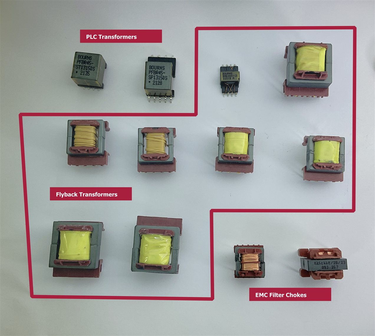
In the image below, you'll find the magnetic components kit generously provided to participants as part of the challenge.
Exploring Project Themes: Learning the Theory of Flyback Transformers
While looking for a topic for my project, I delved into the applications of flyback converters, a concept that initially seemed foreign to me. To my surprise, I discovered that flyback transformers were the same ones that used to intimidate me during my summers working at an Apple repair workshop. These flyback transformers were connected to the CRTs of the early compact Macintosh computers. On the workshop walls, we had instructions on how to discharge the CRT before disassembling the motherboard using two long screwdrivers. Now you can find similar methods on the Internet Discharging the CRT in a compact Mac
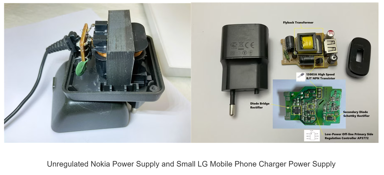
And then, to my astonishment, it turned out that flyback transformers were everywhere – in almost every mobile phone charger, in PC power supplies, in countless electronic devices.
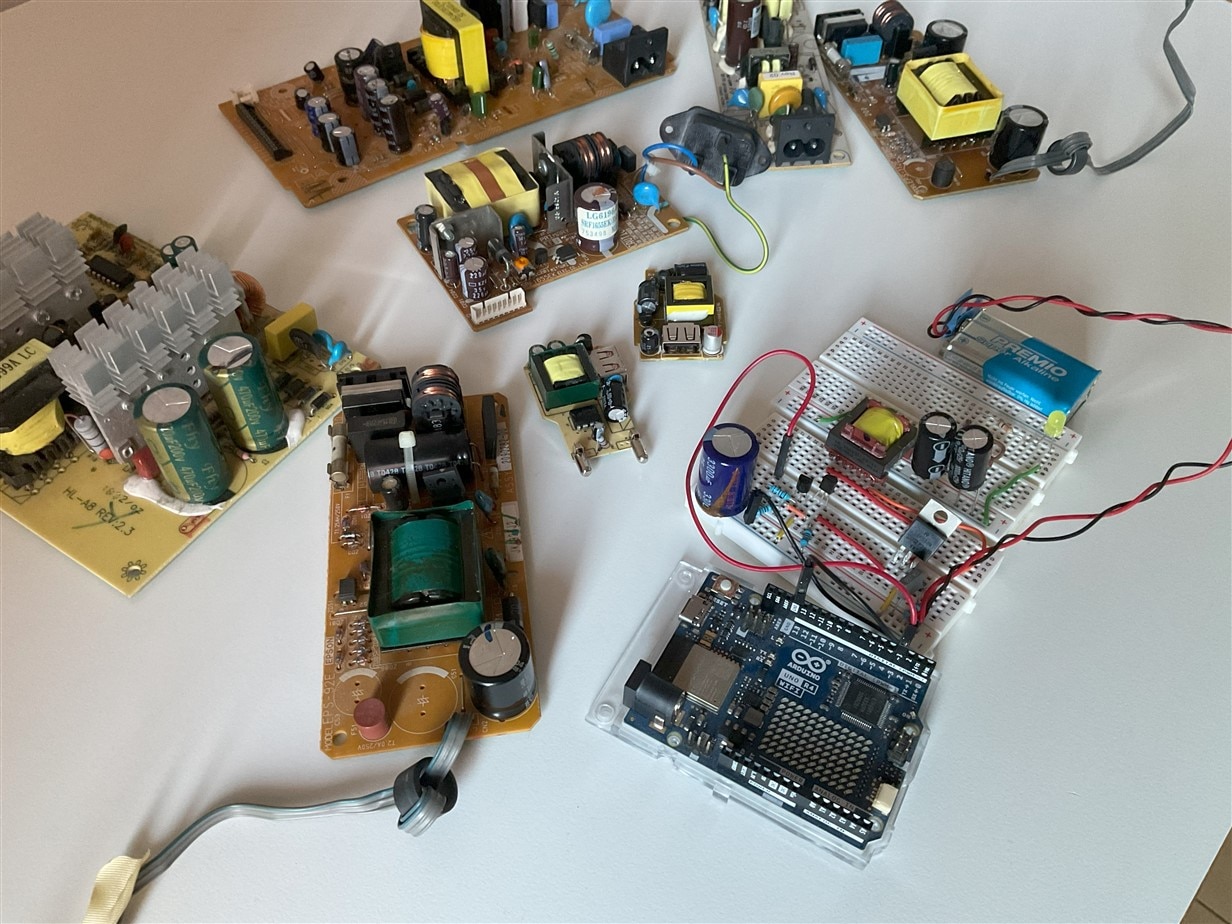
Within my collection of salvaged materials, I discovered several Switched-Mode Power Supplies (SMPS), each housing flyback transformers employed in flyback converter topologies. These power supplies, sourced from discarded equipment, provide a wealth of insights into diverse flyback design approaches. In the image, you'll spot multiple power supplies, some with missing components, which I've repurposed in previous projects.
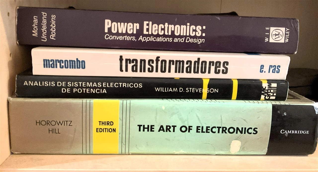
I returned to my university reference book, 'POWER ELECTRONICS Converters, Applications and Design,' written by Ned Mohan, and there were the topologies of flyback DC/DC converters. I searched through the latest edition of 'The Art of Electronics,' and once again, there were dozens of pages dedicated to flyback converters. I wasn't going to be alone.
I took a moment to revisit the foundational lessons on transformers, converters, and electromagnetism contained in my university textbooks. The journey through these pages extended from the older volumes to more contemporary ones, such as "The Art of Electronics" (AoE), as depicted in the image. These books transitioned from the top shelf to the bottom after a thorough dusting-off.
The Clip that Inspired My Magic Lightbox Project
Reviewing commercial applications for flyback converters, one particular use caught my attention – their application as dimming controllers for LED lamps. I've been thinking about a project for a while now, aiming to automate lighting for photographs of small electronic setups or tiny circuit boards – smart lights capable of modifying and controlling image contrast.
So... why not combine these two needs and create this project, The Magic Lightbox? And that's exactly what I did.
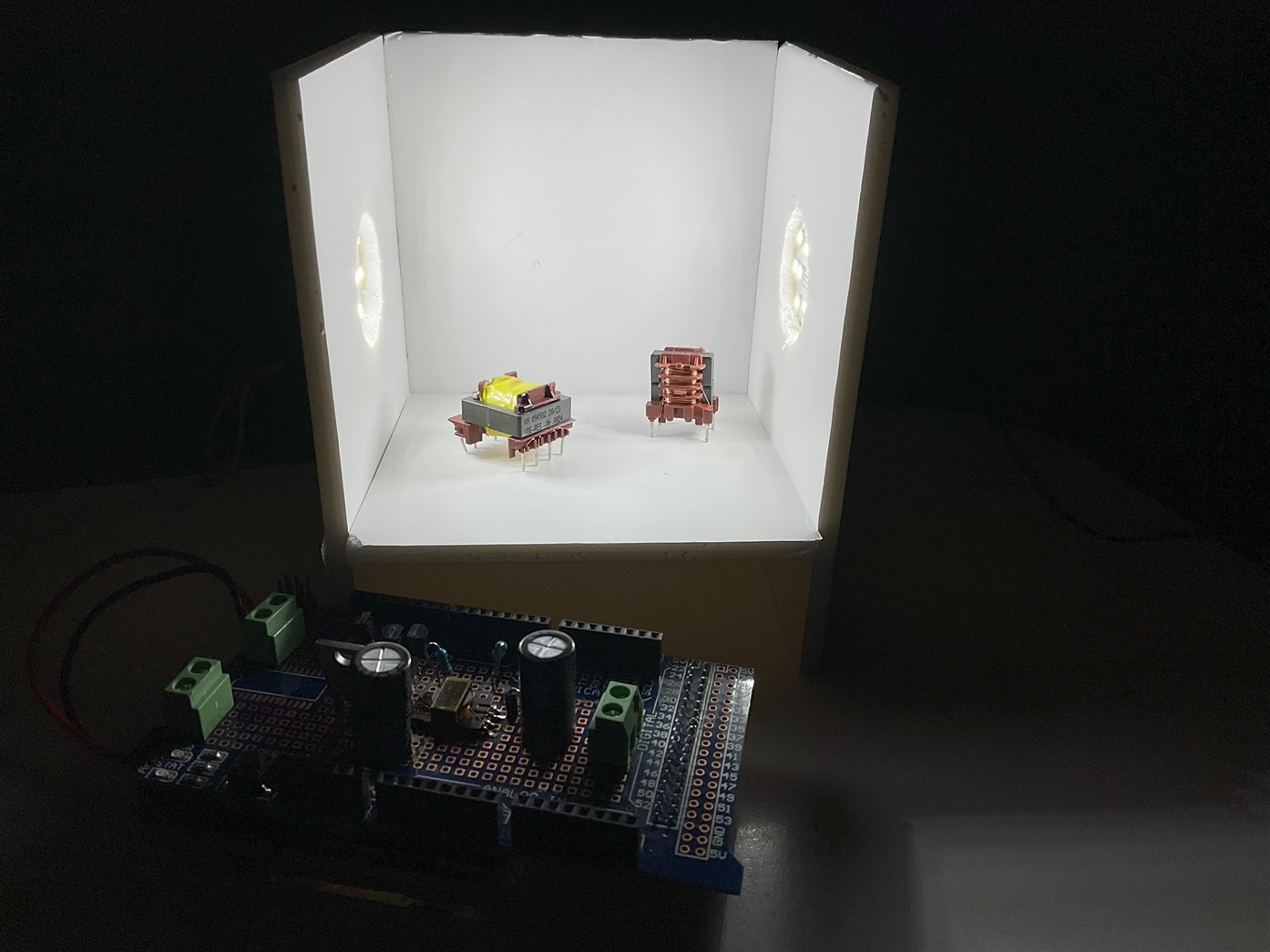
The Magic Lightbox addresses a photography lighting challenge, specifically designed for small objects like electronic components. Comprising two opposing LED panels resembling softboxes, the setup enhances contrast for photographing such components. One softbox features manual dimming, while the other employs an automatic dimming circuit with a switched flyback converter topology, as illustrated in the above image.
To manage contrast, the Magic Light Box systematically alters the LED softbox lighting, adapting it to the level that optimizes contrast. Employing digital image processing, the system evaluates various image aspects, including edge intensity, corner count, and tonal histogram shapes. This dynamic adjustment enhances the lighting conditions for capturing optimal contrast in photographs.
We can employ diverse indices and algorithms to assess the image quality. Our criterion for quality revolves around achieving the highest detail separation. The goal is not artistic photography but rather capturing an image that distinctly reveals the characteristics of the electronic component being photographed.
System overview
The system integrates a PID controller for closed-loop regulation, adjusting Proportional, Integral, and Derivative actions based on the difference between actual and desired states. A Pulse Width Modulation (PWM) controller modifies the duty cycle, regulating energy storage in the Flyback transformer. The Flyback converter provides DC to DC conversion with galvanic isolation, transferring energy from the primary coil to the load through an output capacitor acting as an energy pump. A current probe facilitates non-intrusive current measurement, converting it for analog to digital. The Computer Vision Controller analyzes image contrast, proposing a target current for the PID controller, while a camera captures light, converting it into an electrical signal for digital image processing.
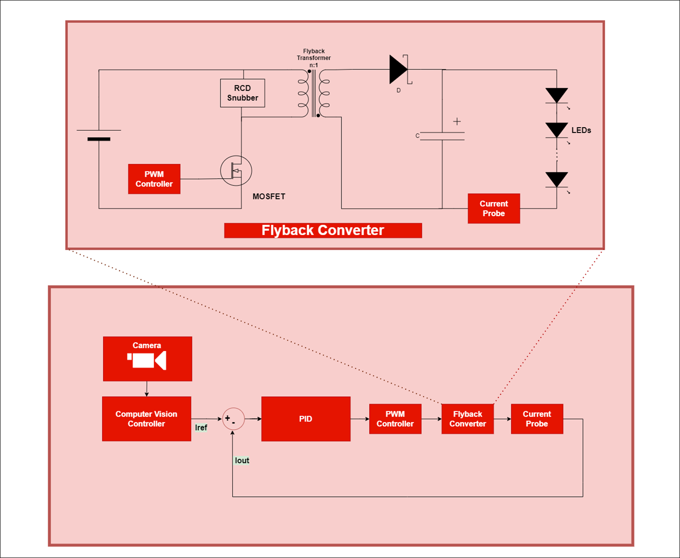
The project has focused on the device that controls the LED panel with automatic dimming. This part of the system utilizes a flyback transformer from the received kit and has allowed me to experiment with this type of transformers. The rest of the system is presented as a justification for the project but has not yet been fully developed.
The Roadmap
Creating the Magic Lightbox involved overcoming a significant challenge – my lack of knowledge about flyback transformers and power converters. To tackle this, I devised a step-by-step plan that would allow me to learn through hands-on experimentation, starting from scratch:
- Study Kit Components: Begin by understanding the contents of the kit and the purpose of each component.
- Explore Flyback Transformers: Dive into the concept of flyback transformers, exploring their functions and experimenting with various configurations. This includes studying the possibilities of placing auxiliary, secondary, or primary windings in series or parallel and exchanging secondary with primary.
- Experiment with Flyback Converter Topologies: Gain insights into flyback converter topologies through practical experimentation.
- Create Prototype: Once a solid understanding is achieved, proceed to create the first prototype on a printed circuit board.
- Build Physical Model: Conclude the project by constructing the physical model of the Magic Lightbox, verifying the results obtained from the experimentation.
Encountering a Few Bumps in the Road
Taking on a bottom-up design challenge, our task was to navigate from a previously specified component to a fully operational system. This scenario resonates with my professional life, where I've often tackled the enhancement of legacy information systems constrained by outdated technologies and specific hardware limitations.
Additionally, we faced the hurdles posed by holiday festivities and the year-end period, which tend to disrupt and extend material delivery timelines. Recognizing this pre-existing constraint, I contemplated approaching the project with recycled materials and whatever was available at home, a challenge that always sparks my motivation.
 Electrical risks without and with galvanic isolation.
In the kit I received, all flyback transformers, except one, were configured to operate with primary voltages ranging from 110 to 220 VAC. Given that my country operates on a 220 V system, prioritizing safety over risk, I opted to work with lower voltages. Since there was only one transformer specifically designed for low-voltage applications, and I aimed to reserve it for the final project, I delved into the realm of creative transformer use to continue my learning journey through experimentation.
A dedicated blog was devoted to exploring transformers, experimenting with various types from the kit, and uncovering insights into their versatile applications.
Unveiling the Special Aspects of Flyback Transformers
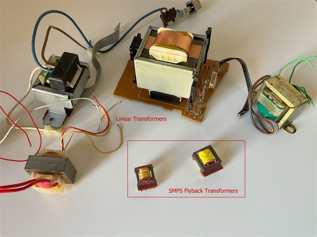
In the course of my exploration, I gained the knowledge to differentiate Flyback Transformers from their linear counterparts. Unlike linear transformers, Flyback Transformers exhibit a unique energy storage and release mechanism, making them particularly suitable for applications requiring efficient energy transfer, such as in switched-mode power supplies (SMPS).
The image captures the distinction between linear transformers, sourced from old power supplies in radios and sound amplifiers, and Flyback Transformers. Noteworthy differences include the size contrast and the unique design of the Flyback Transformers. Unlike linear transformers with laminated iron cores, Flyback Transformers feature cores made of ferrite, concealing a secret gap or airspace within or at the ends of the core arms.
A flyback transformer is a component with primary and secondary windings wound around a core. Unlike traditional transformers, flybacks intentionally include an air gap in the magnetic circuit. This gap alters how energy is stored and released, impacting efficiency. While regular transformers aim for instantaneous energy transfer, flybacks store energy in the core before releasing it.
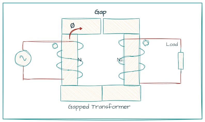
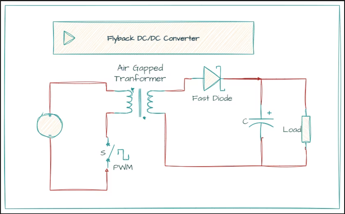
In a typical flyback transformer, a switch (often a power transistor) connects to the primary winding. When the switch is on, the magnetic field gradually builds up in the core. A diode in the secondary part prevents current flow during this stage. When the switch turns off, the primary current is cut, causing a change in voltage polarity on the secondary winding, releasing current in the circuit. Adding a bypass capacitor after the secondary winding helps smooth out ripples from the fast transistor switching.
Comparing Push-Pull Transformers and Flyback Transformers
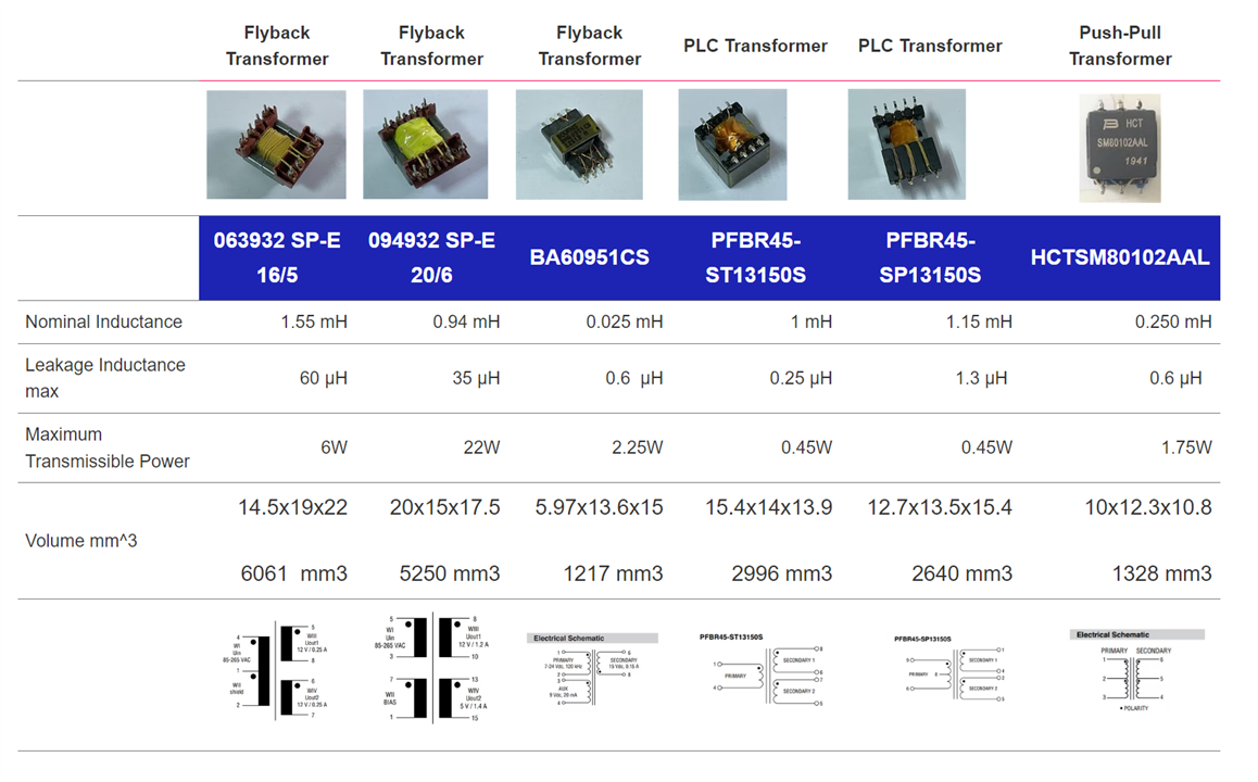
I had some transformers, also manufactured by Bourns and designed for push-pull power converters. I conducted a comparison with Flyback transformers using an impedance analyzer.
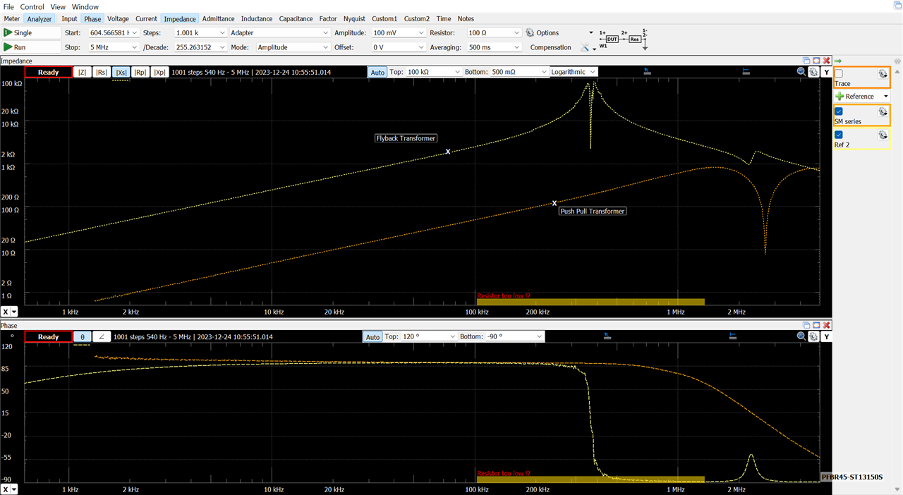
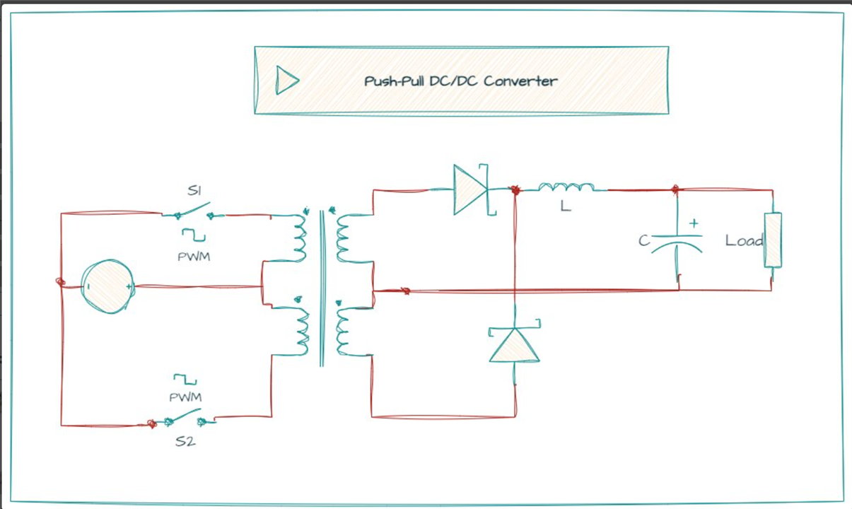
I learned that Push-pull transformers, like the Bourns HCTSM8 series, are commonly used in push-pull DC/DC converter setups. In comparison to flyback converters, which handle a wide range of input voltages but often face EMI issues and require complex closed-loop control systems, push-pull transformers operate more straightforwardly in an open-loop configuration.

Flyback converter topologies generally exhibit lower efficiency and higher energy waste than push-pull topologies, ensuring efficiency and stability with stable input and output current. Push-pull transformers, especially in low-voltage applications, offer the advantage of space efficiency, being smaller in size than flyback transformers.
Designed as "pure" transformers, push-pull transformers typically have physically smaller ferrite cores compared to flyback transformers, with no gap required. This results in high effective permeability and magnetizing inductance, making them compact and efficient, especially in scenarios with tight space considerations.
Continuous mode (CCM) and Discontinuous Mode (DCM)
When designing a flyback transformer, one critical consideration is the mode of operation: Continuous Mode (CCM) or Discontinuous Mode (DCM). In DCM, energy is fully transferred to the secondary winding before the transistor is turned back on, while in CCM, the transistor is turned on before the energy is fully depleted.
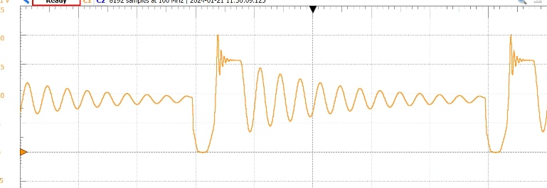
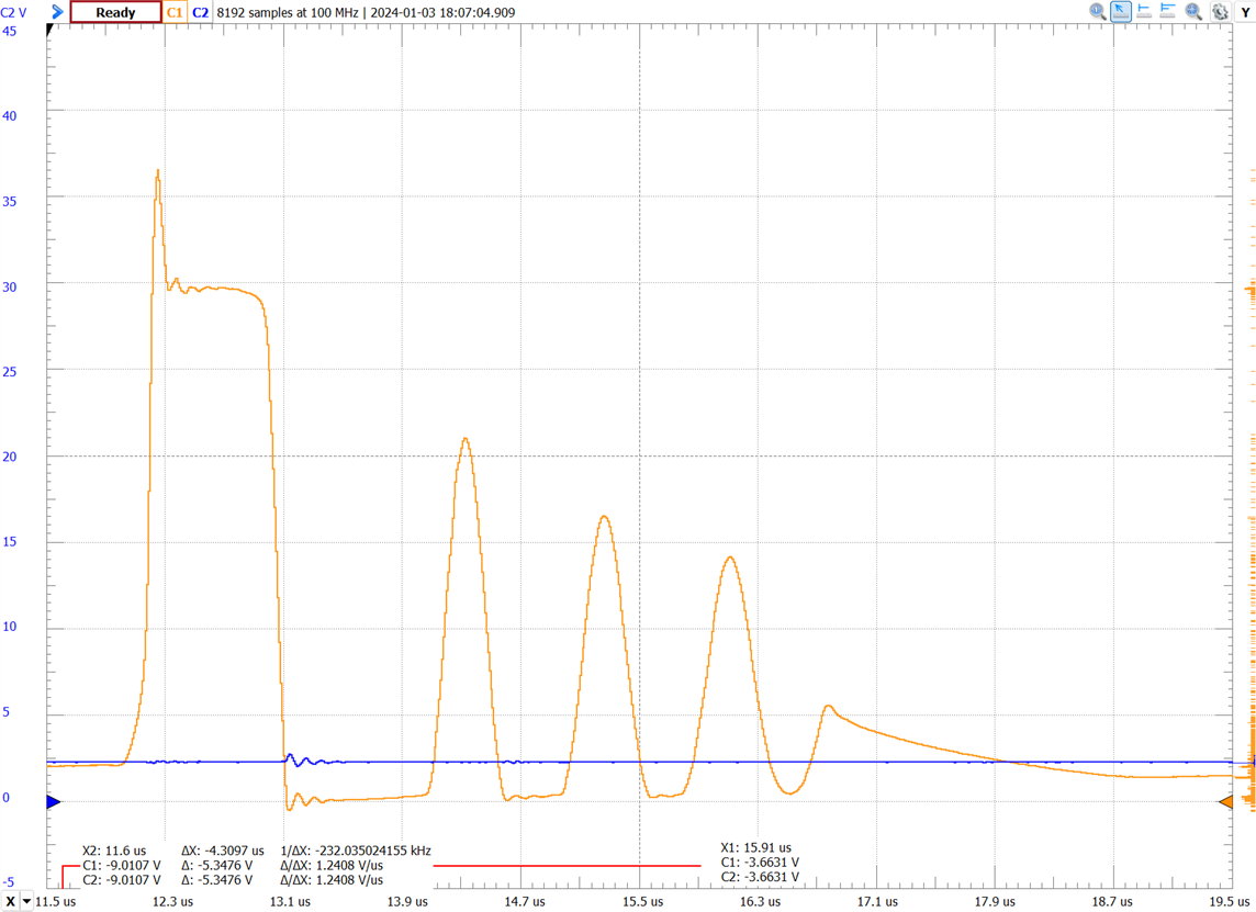
In the image a waveform from my first DIY flyback converter operating in DCM. The waveform shows Voltage between the MOSFET Drain and its source. When the switch is on Drain voltage goes to ground. When the MOSFET turns off, a high-voltage spike occurs on the drain pin because of a resonance between the leakage inductor of the main transformer and the output parasitic capacitance of the MOSFET.
Choosing between Continuous Conduction Mode (CCM) and Discontinuous Conduction Mode (DCM) in a flyback transformer involves trade-offs. DCM is generally more efficient due to reduced diode losses, but overly small duty cycles can impact overall efficiency. While DCM theoretically allows for a smaller transformer, larger wire gauges may be needed. Despite these considerations, transformer sizes in both modes are usually similar. DCM's higher efficiency enables increased switching frequency and the use of a smaller transformer.
Learning how to experimentally identify windings, polarities, and ratios between windings.
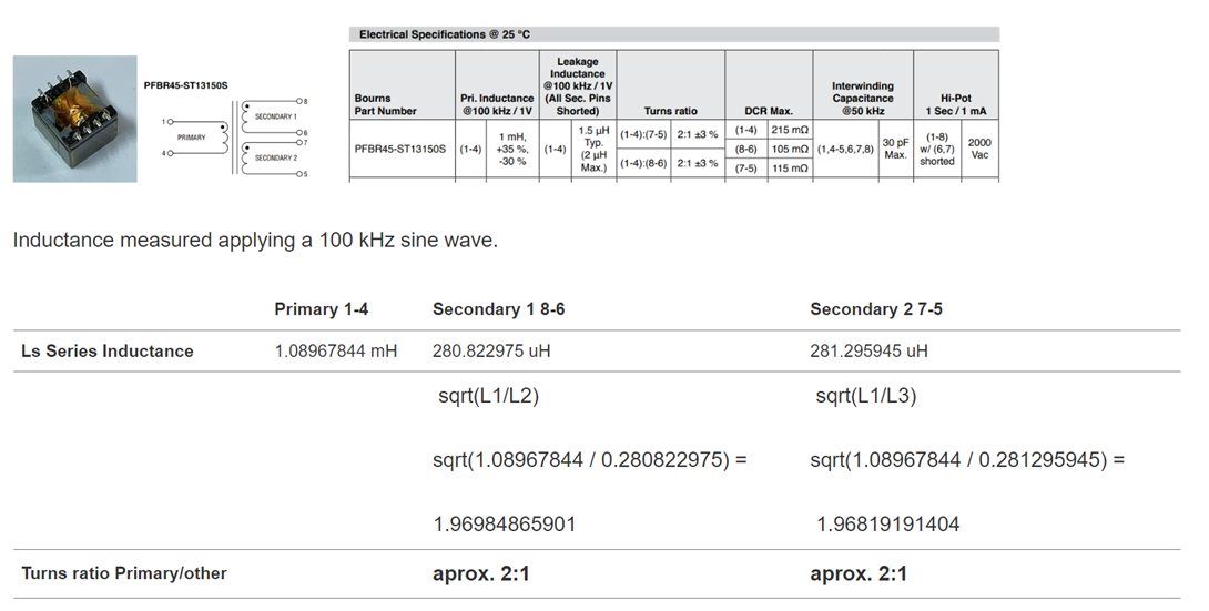
I learned how to experimentally identify polarities, and ratios between windings and of course I documented and tested all those methods
I gained hands-on experience in identifying polarities and ratios between windings experimentally. Documenting and testing various methods allowed me to understand these aspects thoroughly.
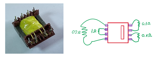
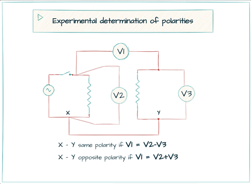
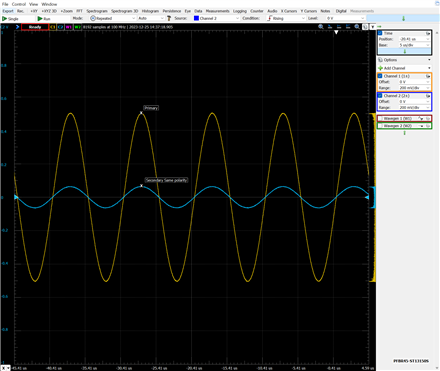
I compared experimental data with theoretical predictions and delved into the nuances of the small differences.
Measuring the transformer impedances
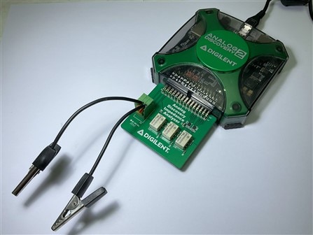
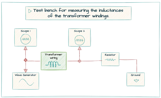
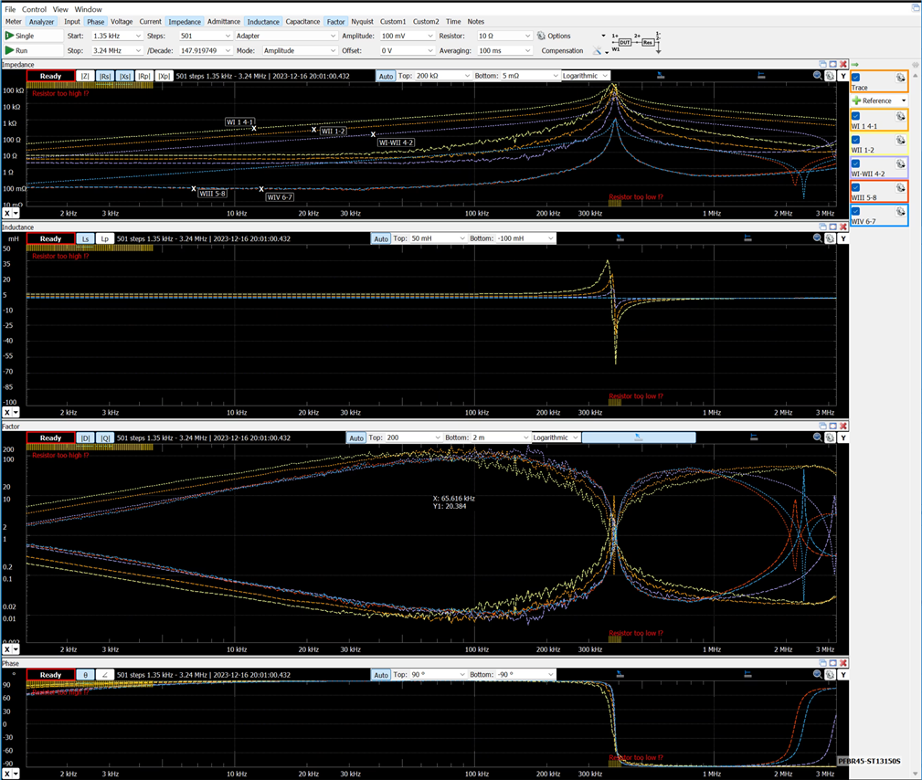
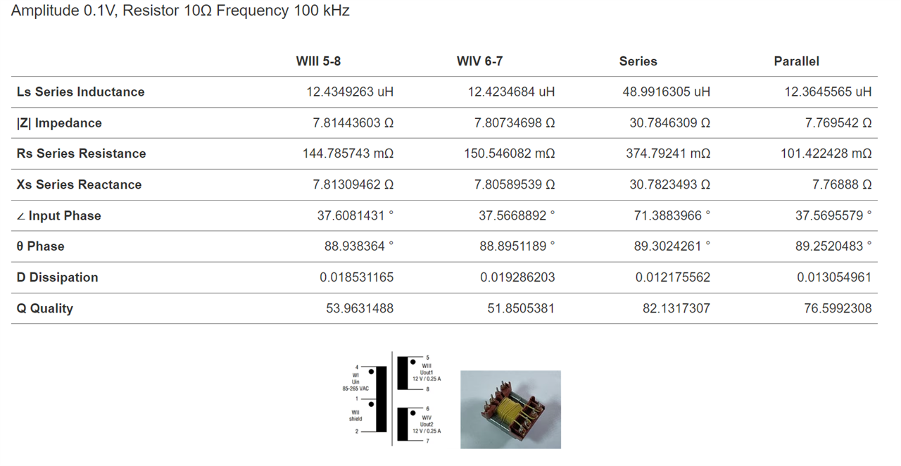
I employed an impedance analyzer to collect detailed data on each component in the kit, enhancing my understanding. The appendix of blog 2 contains comprehensive documentation. The image displays the Digilent Analog Discovery 2 with the Impedance Analyzer Adapter, utilized for analyzing inductive, resistive, and capacitive behaviors in different transformer winding configurations.
Creative Use of Transformers
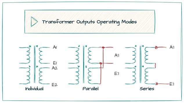
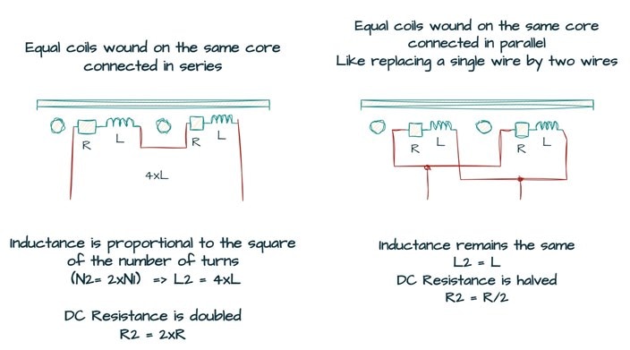
As I mentioned earlier, I found myself needing to take a "creative" approach in utilizing the transformers from the kit. This involved stepping away from their original design and exploring how I could combine different windings, whether in series, parallel or by using different windings as primaries and secondaries. I delved into the theory, conducted experiments, and thoroughly documented the various combinations.
Selecting an operating mode for a transformer involves considering factors like inductance, DC resistance, RMS current, saturation current, self-resonant frequency (SRF), and voltage/isolation/safety. Key considerations include the impact on inductance, resistance, current, saturation, resonant frequency, and safety when connecting windings in parallel or series.

Understanding Flyback Converters
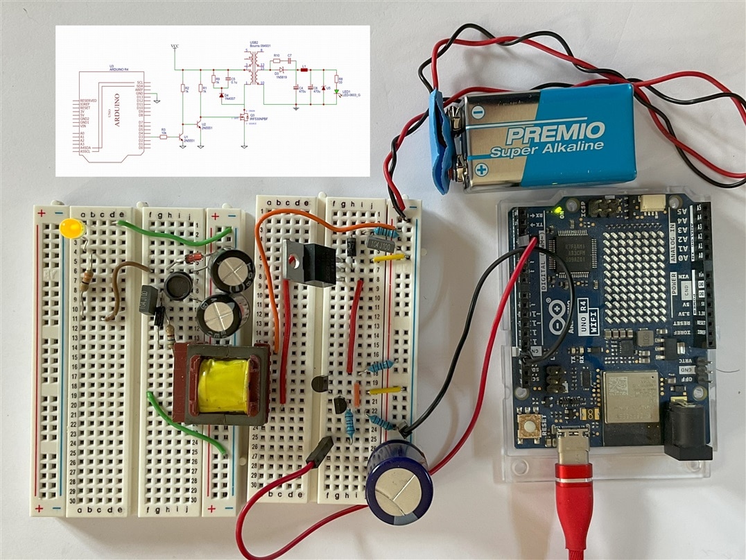
After refreshing my knowledge on transformers and acquiring new insights, I dedicated another blog to the design of power converters under the flyback topology.
Regulation in flyback converters
I delved into the regulation modes employed in flyback switched-mode power supplies. This regulation can be achieved through traditional PWM methods, either in voltage mode or current mode. In voltage mode, the integrated error signal (Verr = Vref − FB) is compared with a sawtooth waveform, adjusting how long the switch stays ON.

On the other hand, current mode PWM utilizes the ramping current in the inductor to initiate each conduction cycle. Both methods are types of voltage regulators, differing in how they use the error signal to adjust pulse width.
Selecting a transformer
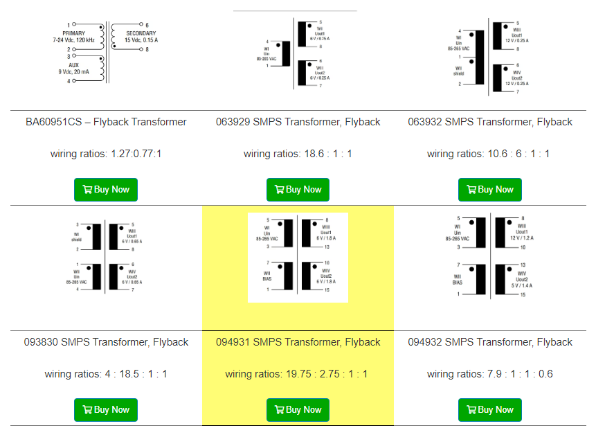
Selecting a transformer for initial experiments with flyback converters, I creatively explored different winding configurations and transformation ratios. Prioritizing safety, I opted for smaller tests using batteries, reserving a dedicated transformer for the final project
Working as a linear power transformer
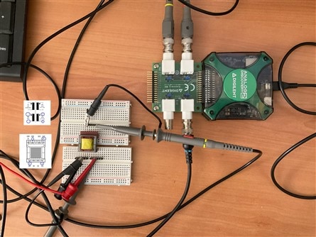
To understand flyback converters, I creatively experimented with the selected transformer. Initially treating it as a linear power transformer, I focused on the BIAS winding and a secondary. Challenges with pin spacing were overcome using two separate breadboards.
Pulse response
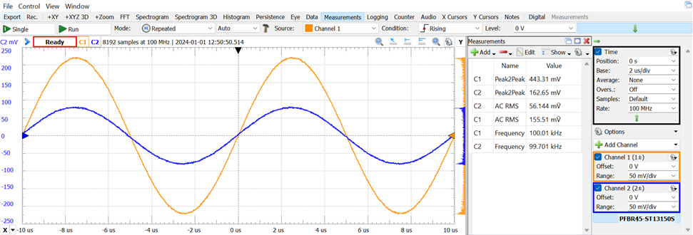
I wanted to observe the behavior of the transformer under pulses since it will be used in a pulsed manner using the signal generator form the Digilent Analog Discovery 2
Generating a 100 kHz PWM signal with an Arduino UNO R4
For the final project, I decided not to use a commercial switch controller chip but rather generate PWM control signals with an Arduino UNO R4. I explored the generation of these PWM signals with the Arduino.
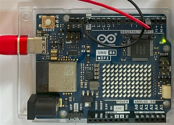
It was really easy to generate a 100 kHz PWM signal from the Arduino, just a couple of lines and some imports.
Driving the MOSFET from the Arduino UNO R4 with an Optocoupler
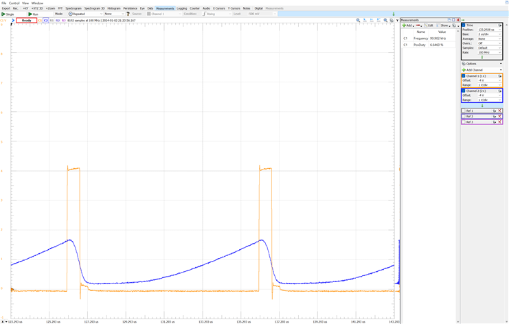
For experimenting with a MOSFET, I considered building a control circuit to isolate the MOSFET from the Arduino using a PC817 optocoupler. Despite the PC817's presence in many power supplies, it proved unsuitable for frequencies above 100 kHz. Despite the attempt, the results were not satisfactory for the intended purposes.
Using BJT transistors to drive the MOSFET from the microcontroller
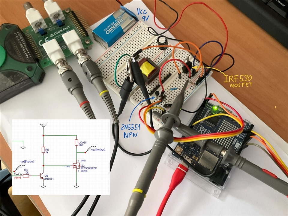
After discarding the optocoupler option, I considered building a driver circuit using two NPN BJT transistors, two 2N5551 transistors. The chosen frequency for the experiments was 100 kHz, requiring a MOSFET balancing low gate charges, low on-resistance (RDS(on)), and high efficiency.

The IRF530 Power MOSFET was selected thinking it was suitable for the experiments. Later on, I replaced the IRF530 MOSFET with an IRF520 after encountering switching time issues with the former.
Attempting to optimize the MOSFET driver
I attempted to save a transistor by inverting the PWM signal at the software level. However, this approach neglected the consequences, allowing the MOSFET to be in the ON state in the absence of a PWM signal, potentially leading to high currents and the risk of damaging the transformer.
The members of the element14 community provided valuable advice, and a clear indication to use a pull-up or pull-down resistor would have sufficed. This was the solution I implemented in the final project, effectively addressing the problem. Additionally, they also advised me on best practices to protect the MOSFET, such as always using a source-to-gate resistor between 100k and 5M Ohms.
Flyback converter without snubbers or voltage clamps
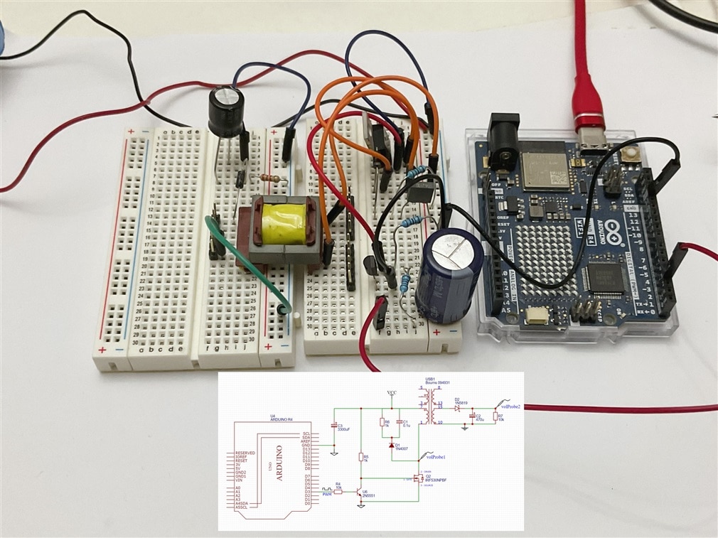
Having successfully generated the PWM signal from the Arduino microcontroller and designed an initial driver for the MOSFET gate, I built a simple Flyback DC/DC converter circuit on a breadboard. It was exciting to witness my first converter in action.
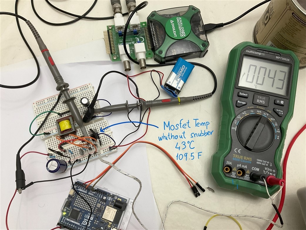
At first, I was a bit terrified. I had the oscilloscope probe without attenuation, and all the measurements turned red. After setting the probe attenuation to x10, everything became clear – there were peaks of 41 volts, even though I was working with a battery that provided only 7.5V
Additionally, something was not right. The MOSFET started to heat up, reaching 43 °C, despite the room temperature being 6 °C with the windows open.
The importance of snubber networks
In a flyback converter, the turn-off of the MOSFET can cause voltage spikes due to leakage inductance. To mitigate this, a primary snubber network is introduced. This network, either a simple RC combination or a more effective DRC network with a diode, helps smooth the transition and prevent unwanted voltage spikes.
Testing was conducted both with and without the primary snubber circuit to observe its impact on voltage spikes,
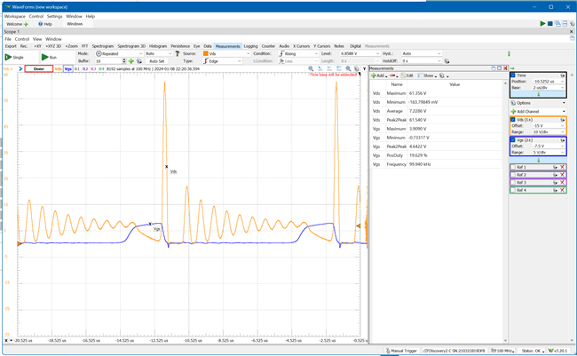
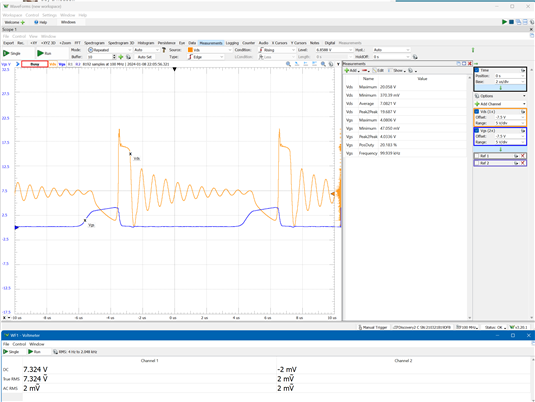
Members of the element14 community clarified something I had suspected, but my lack of confidence prevented me from interpreting it. I was stressing the MOSFET, operating in an inappropriate zone. This also explains the high temperature. I needed to improve the MOSFET driver. It was a valuable learning experience for me, perhaps one of the best in this challenge.
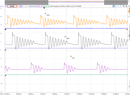
The results of applying the snubber looked promising.
Gluing it all together my first unregulated DC/DC flyback converter.
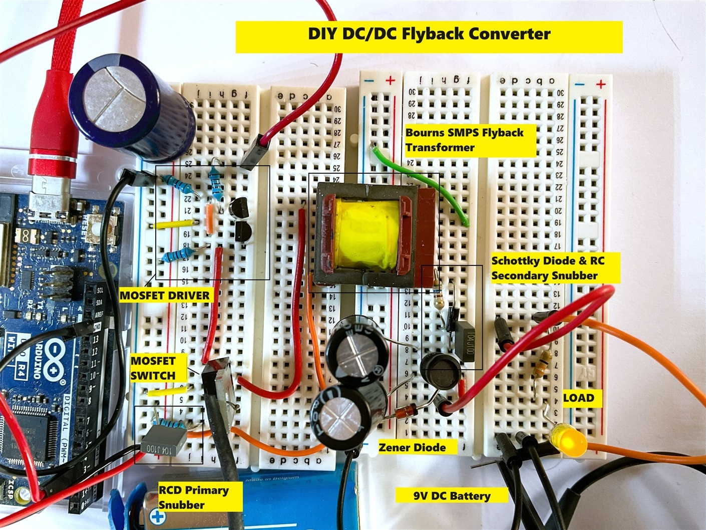
All these sets of tests concluded with cleaning and organizing the circuit built on the breadboard and documenting a series of tests that were recorded in the third blog.
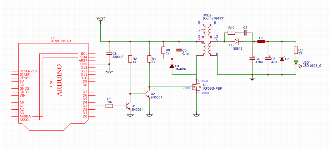
Crafting an unregulated flyback switched-mode DC/DC converter circuit controlled by an Arduino UNO R4 to keep an LED constantly illuminated without flickering. I called this the maker's nightmare because the LED didn't blink.
The use of a Multicomp Pro MP720015 portable oscilloscope was a great help in presenting the results on the blog.

Back to the textbooks and studying about MOSFETs
From all the feedback I received from the kind members of the element14 community, a new "gap" in my knowledge emerged: understanding the MOSFET operating regions well and designing a new driver for the MOSFET. Guided by the books, I decided to try drivers for MOSFET with complementary BJT transistors in a totem-pole configuration.
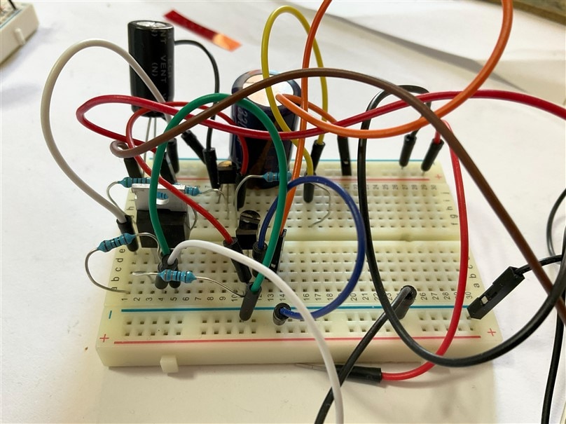
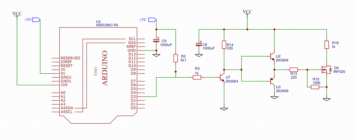
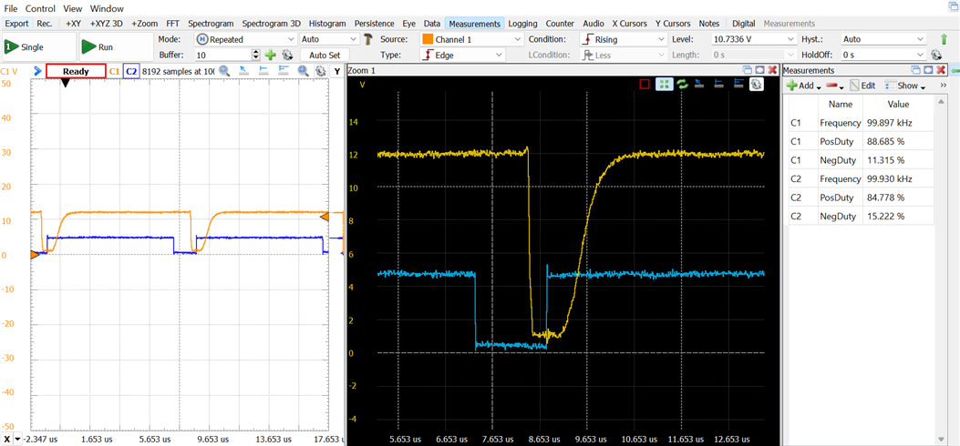
Applying theoretical calculations and attempting improvements led to mixed results. After some uncertainty, I replaced the NPN 2N5551 and its complementary PNP 2N5401 transistors with a pair designed for lower currents: the NPN 2N3904 and the PNP 2N3906. Introducing a preceding inverting stage to ensure safe operation for the Arduino UNO R4 improved things significantly. However, the IRF530 MOSFET still struggled at low duty cycles, prompting me to replace it with an IRF520 MOSFET. Further adjustments to resistor values through trial and error led to a more satisfactory solution.
Developing a soft-start control algorithm for the driver
To alleviate the stress on the MOSFET during startup, I implemented a soft start algorithm in addition to adjusting the software driver to invert the signal. The soft start algorithm gradually adjusts the duty cycle of the PWM signal from zero to the target value, minimizing stress on the MOSFET and preventing potential issues.
Applying the softstart to the MOSFET
Creating an Arduino shield for our DC/DC converter to drive an LED array
After all the new choices and testing on the protoboard, I proceeded to solder everything onto an Arduino shield board. At this point, I haven't added snubber or voltage clamp circuits to observe the oscillations during MOSFET turn-offs once again.
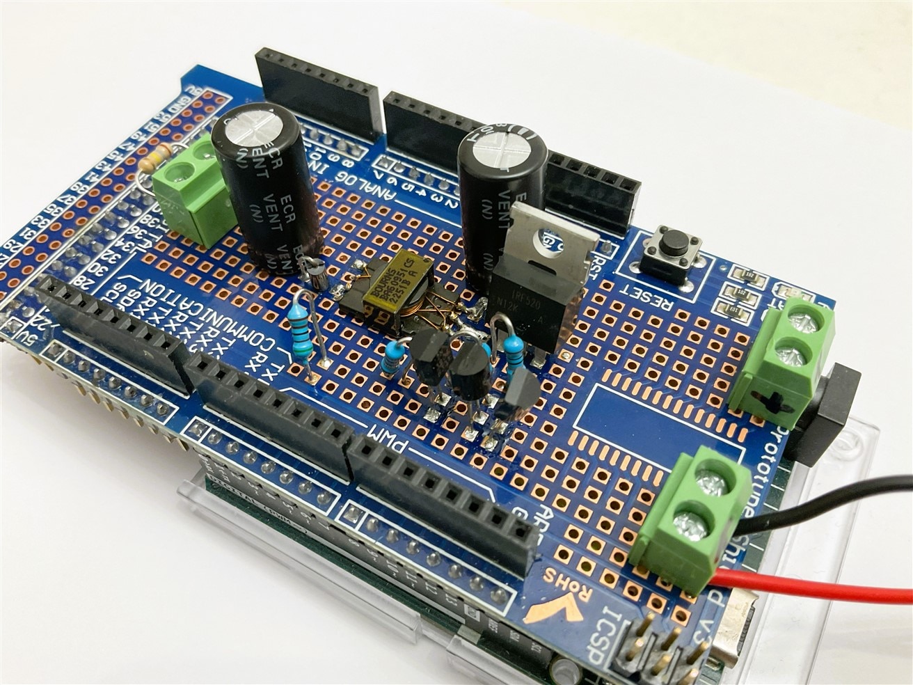
In the next video, the system performs two soft starts after an Arduino reset. Two hard resets. Power comes from a 72-8690A TENMA DC Power Supply. It is powering both the Arduino UNO R4 and the converter that acts as the driver for the LED lamp.
Arduino Shield. Output signal without snubber circuits
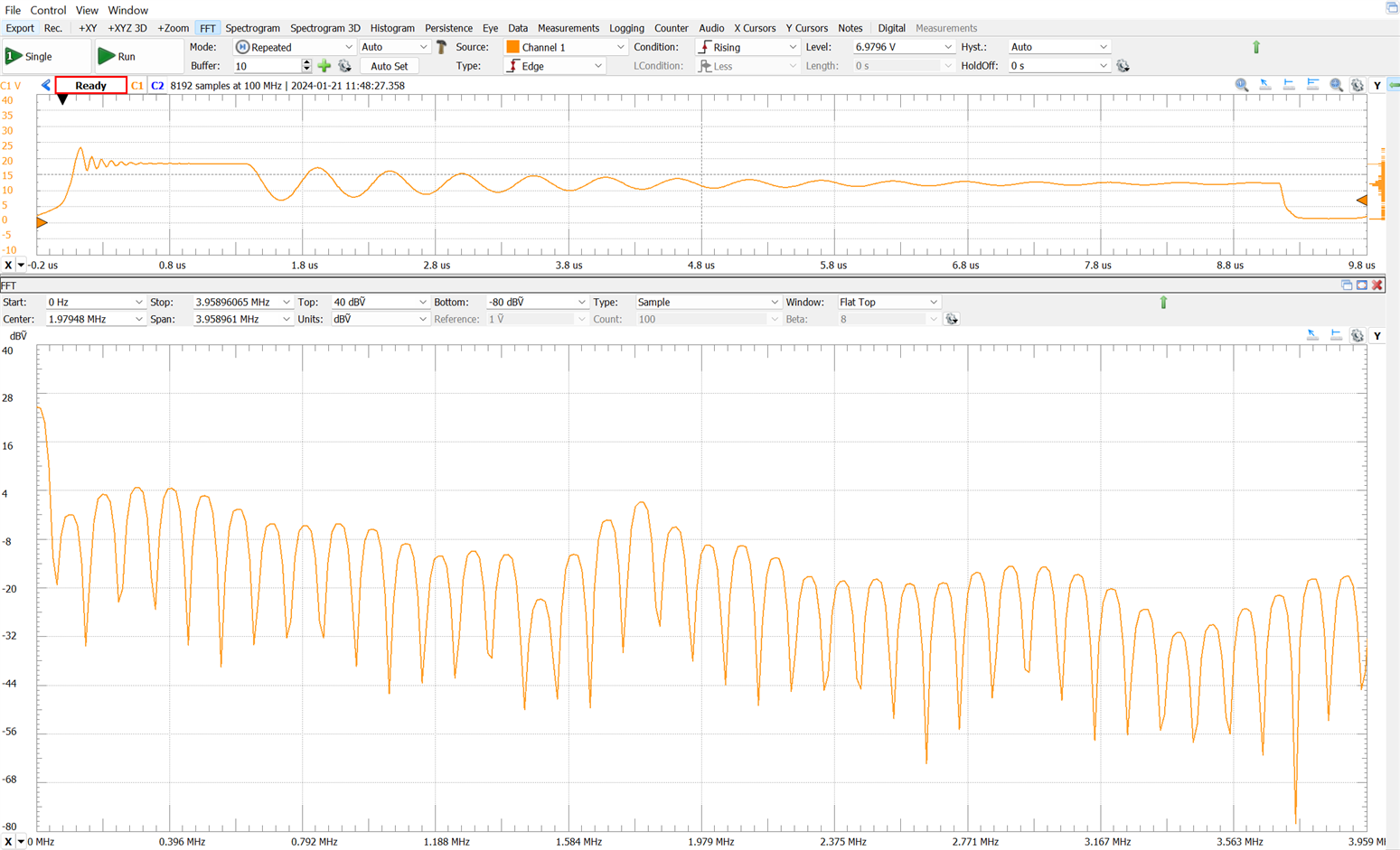
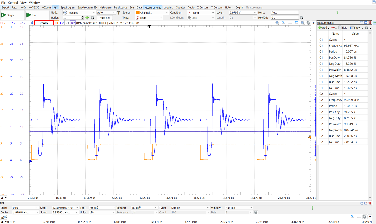
The voltage peaks without the snubbers are high, but not as high as when the tests were conducted on the breadboard. Constructing the circuit on a PCB by soldering the components is much safer for the MOSFET.
Regulation Feedback
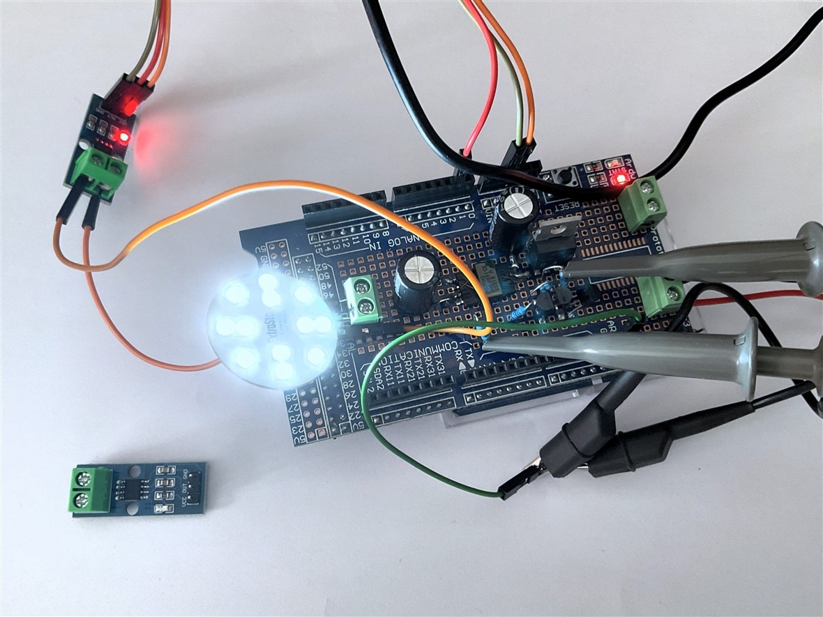
In this project, I explored a different approach to regulation. I wanted to use an Arduino microcontroller for software-based control. The feedback loop involves measurements obtained through a current probe equipped with a Hall-effect sensor. The Arduino Uno R4, powered by a Renesas RA4M1 ARM Cortex M4 CPU, features an Analog-to-Digital Converter (ADC) supporting resolutions up to 14 bits. The ACS172 module, utilizing the ACS712 Hall-Effect-Based Linear Current Sensor IC, serves as the current sensor on the output.
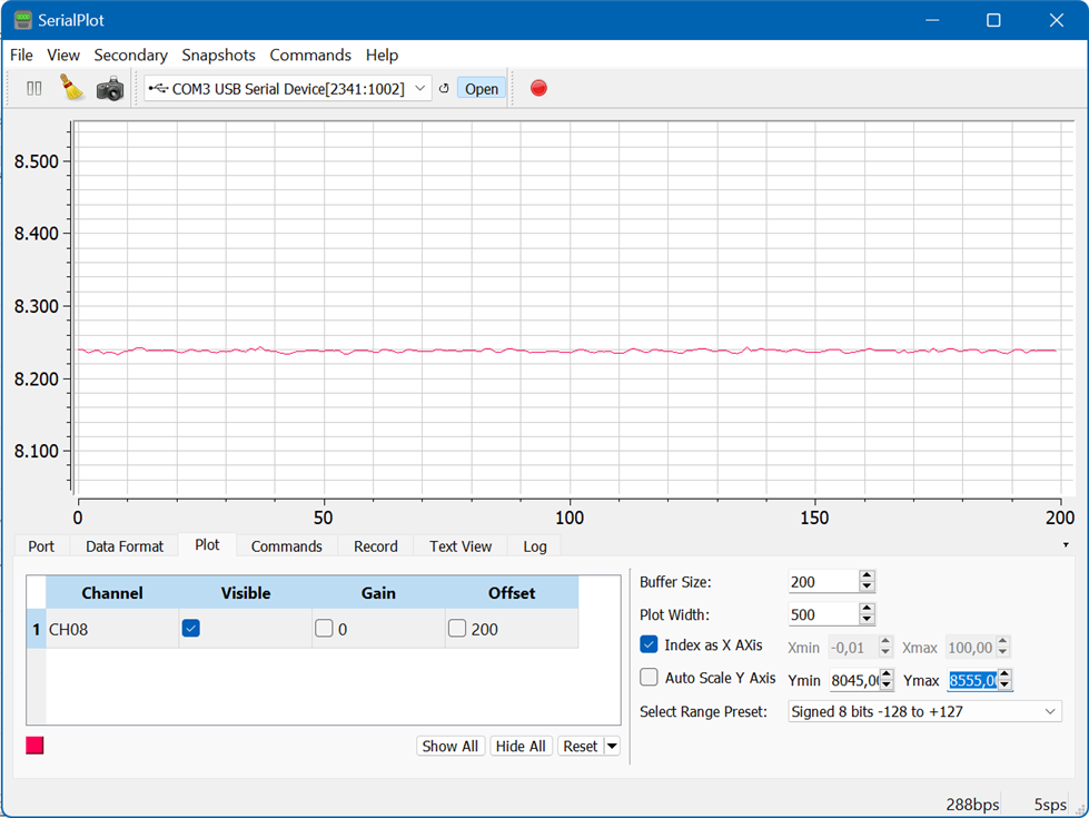
This is the captured data after applying a low pass-filter. Values ranging from 0 to 16384 with 8192 corresponding to 0A. Even with the low pass filter, the signal is still too noisy.
Redesigning the Arduino Shield Circuit
This the electronic circuit governing the automatic dimmable LED panel. In the initial tests of the shield, protections for the MOSFET and secondary diode were omitted. This revision incorporates them for the final prototype.
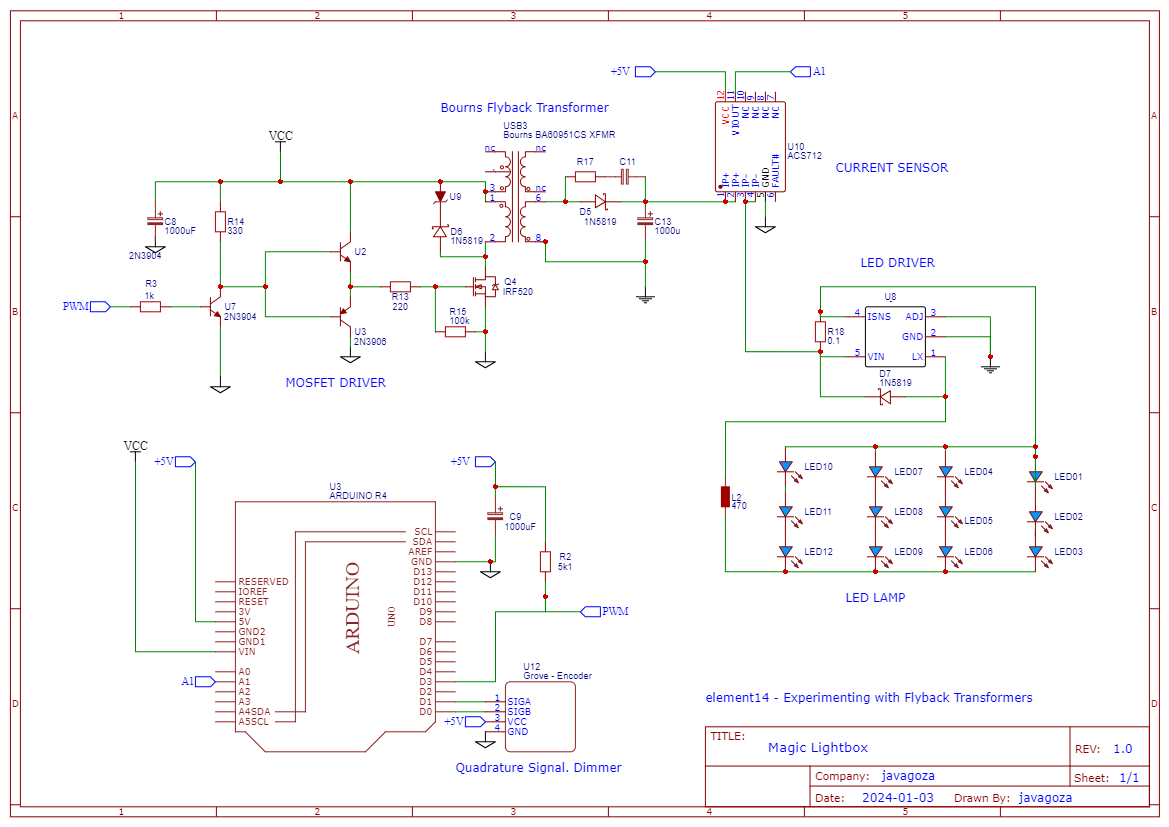
The system's core involves an Arduino UNO R4 generating an inverted PWM signal for MOSFET regulation. This signal passes through an NPN inverter and totem-pole MOSFET driver, optimizing current and voltage for MOSFET switching. A voltage clamp protects the MOSFET from spikes. The Bourns BA60951CS Flyback Transformer stores and releases energy in response to MOSFET switches. A secondary diode with an RC snubber network and a filter capacitor ensures controlled energy flow. The load comprises 12 LEDs controlled by a CL6807 LED driver. A dedicated current sensing probe integrates with Arduino's ADC, providing real-time monitoring. The system uses a rotary encoder for dynamic setpoint adjustments.
Real-time adjustment of the Flyback converter's duty cycle through the rotary encoder
In the video, you can see how the duty cycle is controlled using a rotary encoder. Each pulse from the encoder corresponds to a 1% increase or decrease in the duty cycle. A protection window is in place to prevent exceeding maximum levels. While the ideal control method involves current feedback, the current stage of development focuses on duty cycle control for training the PID controller with observed values.
Crafting the Magic Lightbox Prototype: From Concept to Foam Board Reality
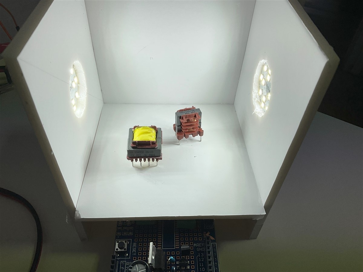
An image is worth a thousand words. Here is the prototype of the Magic Lightbox built with foam board panels.

Two images are worth two thousand words; here are the additional 1000 words.
Magic Lightbox Blog Series
If you want more details on the topics I've covered in this summary of my experience during this design challenge, here is a list of links to the previous 5 blogs.
- Blog 1 - Magic Lightbox: Smart LED Dimmer Flyback Driver Project Introduction.
- Blog 2 - Magic Lightbox: Understanding Flyback Transformers. How to characterize them.
- Blog 3 - Magic Lightbox: Understanding Flyback Converters.
- Blog 4 - Magic Light Box: DC/DC Flyback Converter Testbench and LED Dimmer Driver
- Blog 5 - Magic Light Box: Building The Prototype
- Final - Magic Lightbox: Project Summary
Conclusion
The “Experimenting with Flyback Transformers " Design Challenge has been an extraordinary journey filled with valuable lessons and insights into the world of flyback converters. The success of the project can be attributed to the extensive support of the element14 community, which provided me with invaluable guidance and feedback throughout the experimentation process.
While there were challenges, particularly in the early stages with MOSFET drivers, overcoming them proved to be an invaluable learning experience. The iterative process of design, testing and refinement led to a comprehensive understanding of flyback converters and their applications.
I would like to express my gratitude to element14 for selecting me for this challenge and to Bourns for their sponsorship. The opportunity to explore and experiment with flyback transformers has not only improved my technical skills but has also deepened my appreciation for collaborative learning within the maker community.
I hope that others have enjoyed reading my blogs and exploring the experiments as much as I did. A heartfelt thank you to the other participants who generously shared their knowledge. The collaborative spirit and shared enthusiasm in this challenge have truly made it a valuable experience. Best wishes to everyone in their future endeavors!


-

Anthocyanina
-
Cancel
-
Vote Up
0
Vote Down
-
-
Sign in to reply
-
More
-
Cancel
Comment-

Anthocyanina
-
Cancel
-
Vote Up
0
Vote Down
-
-
Sign in to reply
-
More
-
Cancel
Children