element14 Community
element14 Community
    Register Log In
  • Site
  • Search
  • Log In Register
  • Community Hub
    Community Hub
    • What's New on element14
    • Feedback and Support
    • Benefits of Membership
    • Personal Blogs
    • Members Area
    • Achievement Levels
  • Learn
    Learn
    • Ask an Expert
    • eBooks
    • element14 presents
    • Learning Center
    • Tech Spotlight
    • STEM Academy
    • Webinars, Training and Events
    • Learning Groups
  • Technologies
    Technologies
    • 3D Printing
    • FPGA
    • Industrial Automation
    • Internet of Things
    • Power & Energy
    • Sensors
    • Technology Groups
  • Challenges & Projects
    Challenges & Projects
    • Design Challenges
    • element14 presents Projects
    • Project14
    • Arduino Projects
    • Raspberry Pi Projects
    • Project Groups
  • Products
    Products
    • Arduino
    • Avnet & Tria Boards Community
    • Dev Tools
    • Manufacturers
    • Multicomp Pro
    • Product Groups
    • Raspberry Pi
    • RoadTests & Reviews
  • About Us
    About the element14 Community
  • Store
    Store
    • Visit Your Store
    • Choose another store...
      • Europe
      •  Austria (German)
      •  Belgium (Dutch, French)
      •  Bulgaria (Bulgarian)
      •  Czech Republic (Czech)
      •  Denmark (Danish)
      •  Estonia (Estonian)
      •  Finland (Finnish)
      •  France (French)
      •  Germany (German)
      •  Hungary (Hungarian)
      •  Ireland
      •  Israel
      •  Italy (Italian)
      •  Latvia (Latvian)
      •  
      •  Lithuania (Lithuanian)
      •  Netherlands (Dutch)
      •  Norway (Norwegian)
      •  Poland (Polish)
      •  Portugal (Portuguese)
      •  Romania (Romanian)
      •  Russia (Russian)
      •  Slovakia (Slovak)
      •  Slovenia (Slovenian)
      •  Spain (Spanish)
      •  Sweden (Swedish)
      •  Switzerland(German, French)
      •  Turkey (Turkish)
      •  United Kingdom
      • Asia Pacific
      •  Australia
      •  China
      •  Hong Kong
      •  India
      •  Japan
      •  Korea (Korean)
      •  Malaysia
      •  New Zealand
      •  Philippines
      •  Singapore
      •  Taiwan
      •  Thailand (Thai)
      •  Vietnam
      • Americas
      •  Brazil (Portuguese)
      •  Canada
      •  Mexico (Spanish)
      •  United States
      Can't find the country/region you're looking for? Visit our export site or find a local distributor.
  • Translate
  • Profile
  • Settings
Experimenting with Magnetic Components
  • Challenges & Projects
  • Design Challenges
  • Experimenting with Magnetic Components
  • More
  • Cancel
Experimenting with Magnetic Components
Blog Experimenting with Magnetic Components - Make your own Inductor
  • Blog
  • Forum
  • Documents
  • Files
  • Mentions
  • Sub-Groups
  • Tags
  • More
  • Cancel
  • New
  • Share
  • More
  • Cancel
Group Actions
  • Group RSS
  • More
  • Cancel
Engagement
  • Author Author: Jan Cumps
  • Date Created: 19 Oct 2021 11:48 AM Date Created
  • Views 4999 views
  • Likes 2 likes
  • Comments 7 comments
  • common_mode_choke
  • common_mode_rejection
  • experimenting_with_magnetic_components
  • magnetic_components
  • bourns
Related
Recommended

Experimenting with Magnetic Components - Make your own Inductor

Jan Cumps
Jan Cumps
19 Oct 2021

I'm reviewing a set of inductors for the Experimenting with Magnetic Components design challenge.

In this post: make a custom inductor

image


Balanced Twisted Windings Common Mode Choke


I'm designing a sister for the common mode choke that was used in the previous post.

There are several ways to wind a common mode choke on a coax core.

The easiest is to wind each inductor on one side of the core, Both in the same direction.
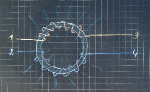
 

image


To reduce the magnetic field that's emitted from the device, you can use another technique: twisted wire winding.

This will concentrate the magnetic field in the inside (eye) of the core.
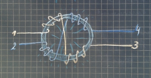
 

image

I used 12 13 windings for each inductor. 6 turning right, then cross over and under, then 6 left windings.
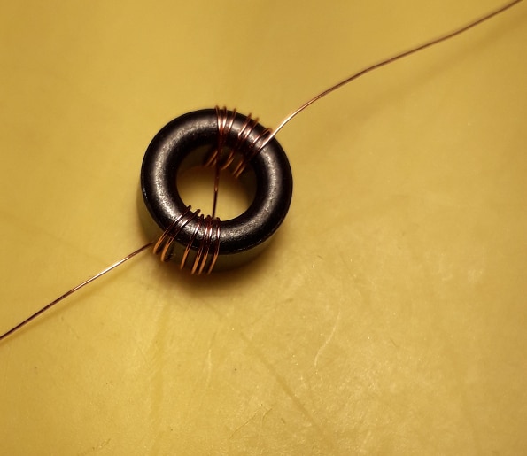
image


Parts


You need a ferrite core. I used a small diameter one from Lairdsmall diameter one from Laird (datasheet).

Get some enameled copper wire from the transformer of a defunct device. Take wire that can be handled with ease.

Optionally, masking tapemasking tape.

The components were part of a shopping cart I won with Project14.


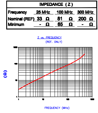
Core specifications:

Laird 28B0375-400 ferrite cylindrical core, 81 ohm, 4.83 mm length, 5.08 mm inner diameter, 9.53 mm outer diameter

NiZn ferrite
image

image source: Laird datasheet


Measurements


It would be great if someone that owns a magnetic field probe could measure the difference in emission of both winding options.

The twisted wire one should have a much smaller magnetic field, concentrated inside the core. The common one's field spreads on the outside of the core.


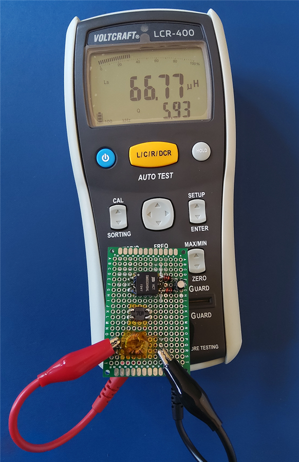
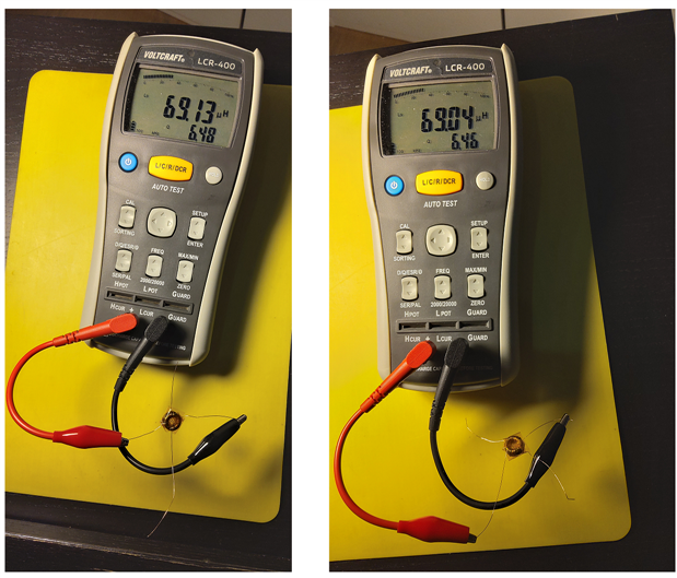
With an LCR meter, the two inductors measure almost identical.

12 13 turns (6 left, 6 right and the crossover one in the middle) for both.

Frequency: 100 kHz
image


attributeinductor ainductor b
L66.85 µH67.01 µH
Q5.995.97
ESR7.05 Ω7.05 Ω
ϕ80.4°80.4°
D0.1680.167
RS7.042 Ω7.045 Ω
DCR0.09 Ω0.09 Ω


image


In the next post (or in the comments), I'll try to show the common mode rejection capabilities.


Related posts
1. Boost Converter part 1: Inductor and Calculations
2. Boost Converter part 2: Build
3. Boost Converter part 3: Measure the Inductor in action
4. LCR meter experiments
5. SMD transformers experiment gizmo part 1: Build
6. SMD transformers experiment gizmo part 2: Measure
7. Common Mode Choke
8. Make your own Inductor
9. Calculate your own Inductor
10. Boost Converter part 4: Efficiency
11. DIY Inductance Meter
Planar PCB Transformer: GaN Point of Load converter 48V to 1V 50A
Measure Unknown Inductor Value with Function Generator and Oscilloscope
Experimenting with Magnetic Components: About the Competition
  • Sign in to reply
  • Jan Cumps
    Jan Cumps over 4 years ago

    A magnetics topic that's not that much talked about here, is planar PCB transformers.


    Planar transformer surrounded by a ferrite core

    (two half cores that connect trough rectangular openings in the PCB)

    10 layer board with 5 primary windings and 1 secondary winding

    image

    Layers 1,4,5,7,10 dedicated to the secondary side (each one turn in parallel) and the other to the primary side (one turn each in series).


    The stacking goes S PP SS P S PP S (S=secondary P= primary).


    image


    These are inductors worked into a PCB. I've reviewed a 5:1 10-layer one here: https://www.element14.com/community/groups/power-management/blog/2017/02/10/gan-point-of-load-converter-48v-to-1v-50a-pa… .

    • Cancel
    • Vote Up 0 Vote Down
    • Sign in to reply
    • More
    • Cancel
  • Jan Cumps
    Jan Cumps over 4 years ago

    I'm running into my lab's limits when trying to measure the differential noise.


    image


    I'm using a known noisy supply as input (noisy in the RF range), and try to show how how the common noise part is rejected.

    It looks impressive on the oscilloscope, but it's deceiving. I get the same image when I unplug the supply.

    There are times when you have to admit that you're not equipped for a particular test.

    image

    • Cancel
    • Vote Up 0 Vote Down
    • Sign in to reply
    • More
    • Cancel
<
element14 Community

element14 is the first online community specifically for engineers. Connect with your peers and get expert answers to your questions.

  • Members
  • Learn
  • Technologies
  • Challenges & Projects
  • Products
  • Store
  • About Us
  • Feedback & Support
  • FAQs
  • Terms of Use
  • Privacy Policy
  • Legal and Copyright Notices
  • Sitemap
  • Cookies

An Avnet Company © 2026 Premier Farnell Limited. All Rights Reserved.

Premier Farnell Ltd, registered in England and Wales (no 00876412), registered office: Farnell House, Forge Lane, Leeds LS12 2NE.

Follow element14

  • X
  • Facebook
  • linkedin
  • YouTube